
Create successful ePaper yourself
Turn your PDF publications into a flip-book with our unique Google optimized e-Paper software.
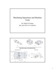
<strong>Welding</strong> <strong>and</strong> <strong>Allied</strong> <strong>Processes</strong><br />
Manual Arc <strong>Welding</strong><br />
Dr. Pulak M. P<strong>and</strong>ey<br />
http://paniit.iitd.ac.in/~pmp<strong>and</strong>ey<br />
http:// paniit.iitd.ac.in/~pmp<strong>and</strong>ey
Fundamentals<br />
The term joining refers to welding, brazing, soldering <strong>and</strong><br />
adhesive bonding. In these process a permanent joint between the<br />
parts is formed <strong>and</strong> cannot be separated easily.<br />
The term assembly usually refers to mechanical methods of<br />
fastening the parts together. Some of these methods allow easy<br />
disassembly, while others do not.<br />
<strong>Welding</strong> is a material joining process in which two or more parts<br />
are coalesced (joined together) at their contacting surfaces by a<br />
suitable application of heat <strong>and</strong>/or pressure. Sometimes parts are are<br />
united together by application of pressure only without external external<br />
heat.<br />
In some welding process a filler material is added to facilitate<br />
coalescence.<br />
<strong>Welding</strong> is most commonly associated with metallic parts but for<br />
plastics also it is used.
Types of welding processes<br />
Solid state welding processes<br />
Liquid state welding processes<br />
Solid / Liquid state bonding processes
Solid-state Solid state <strong>Welding</strong> <strong>Processes</strong><br />
In solid state welding the surfaces to be joined are<br />
brought into close proximity by:<br />
Heating the surfaces without causing melting <strong>and</strong><br />
applying normal pressure<br />
Providing relative motion between the two surfaces <strong>and</strong><br />
applying light normal pressure<br />
Applying high pressure without heating<br />
In these processes the materials remain in solid<br />
state <strong>and</strong> welding is achieved through the<br />
application of heat <strong>and</strong> pressure, or high pressure<br />
only
Forge welding<br />
Forge welding is the oldest method of welding in the category of<br />
solid state welding.<br />
Surfaces to be joined are heated till they are red hot <strong>and</strong> then<br />
forced together by hammering.<br />
It is a crude method of welding <strong>and</strong> quality depends upon the<br />
skill of the welder.<br />
A modern version of this type of welding is manufacture of butt-<br />
welded pipes. In this process, the skulp heated up to the required<br />
welding temperature is pulled through die which forces the two<br />
edges of the heated skulp to contact under pressure <strong>and</strong> get<br />
welded.
Friction <strong>Welding</strong><br />
In this process the two surfaces to be welded are rotated relative relative<br />
to each other under light normal pressure. When the interface<br />
temperature reaches due to frictional rubbing <strong>and</strong> when it reaches reaches<br />
the required welding temperature, sufficient normal pressure is<br />
applied <strong>and</strong> maintained until the two pieces get welded.
Explosion <strong>Welding</strong><br />
<strong>Welding</strong> is achieved in this process by very high contact pressure pressure<br />
developed by detonating a thin layer of explosive placed over one one<br />
of the pieces to be joined. The detonation imparts high kinetic<br />
energy to the piece which on striking the other piece causes plastic plastic<br />
deformation <strong>and</strong> squeezes the contaminated surface layers out of<br />
the interface resulting in a high quality welded joint. No filler filler<br />
material is used <strong>and</strong> no diffusion takes place. The nature of bond bond<br />
is<br />
metallurgical, in many cases combined with a mechanical<br />
interlocking that results from rippled or wavy interface between the<br />
metals.
Liquid State (Fusion) <strong>Welding</strong> <strong>Processes</strong><br />
Arc <strong>Welding</strong><br />
Resistance welding<br />
Oxyfuel gas welding<br />
Other processes<br />
There are two inherent problems with fusion<br />
welding<br />
Effect of localized heating <strong>and</strong> rapid cooling on the<br />
microstructure <strong>and</strong> properties of the parent metals.<br />
Effect of residual stresses developed in the parent<br />
metals due to restrained expansion or contraction. This<br />
effect the impact <strong>and</strong> fatigue life of weldment. weldment.
Arc <strong>Welding</strong><br />
In Electric Arc <strong>Welding</strong> a sustained arc provides the heat required<br />
for melting the parent as well as filler material.<br />
The workpiece <strong>and</strong> the electrode are connected to the two materials<br />
of the power source. The arc is started by momentarily touching<br />
the electrode on to the workpiece <strong>and</strong> then withdrawing it to a short<br />
distance (a few mm) from the workpiece. workpiece<br />
When the electrode <strong>and</strong> workpiece are in contact, current flows <strong>and</strong><br />
when they are separated an arc is generated <strong>and</strong> the current<br />
continues to flow.<br />
The arc is generated by the electrons liberated form cathode <strong>and</strong><br />
moving towards anode.<br />
The arc changes electrical energy into heat <strong>and</strong> light.<br />
Arc <strong>and</strong> power Source characteristics are given in the figure.<br />
figure
About 70% of the heat liberated due to striking of electrons at<br />
anode raises the anode temperature to a very values (5,000 to<br />
30,000 oC). C). This heat melts the base metal as well as tip of the<br />
electrode in the area surrounding the arc.<br />
A weld is formed when when when the mixture of molten base<br />
<strong>and</strong> electrode metal solidifies in the weld area.<br />
Since 70% heat is generated at anode a workpiece connected to<br />
anode will melt 50% faster as compared to if connected with<br />
cathode. This is why workpiece is usually made positive <strong>and</strong><br />
electrode as negative <strong>and</strong> is termed as straight polarity.<br />
When the work <strong>and</strong> electrode connections are reversed, reversed<br />
polarity is said to be employed.<br />
Both direct current (DC) <strong>and</strong> alternating currents (AC) are used<br />
in arc welding. AC machines are less expensive to purchase <strong>and</strong><br />
operate, but generally restricted to welding of ferrous metals.<br />
DC equipment can be used on all metals with good results <strong>and</strong> is<br />
generally noted for better arc control.
The used can be either non-consumable non consumable or consumable.<br />
Consumable electrodes usually have a coating on its outer surface surface<br />
which on melting release gases like hydrogen or carbon dioxide to to<br />
form a protective covering around the molten pool.<br />
The electrode coating also reacts to from slag which is a liquid, liquid,<br />
lighter<br />
than the molten metal. The slag therefore rises to the surface <strong>and</strong> <strong>and</strong><br />
on<br />
solidification forms a protective covering over the hot metal. This This<br />
also<br />
slows down the rate of cooling of the weld. The slag layer can be be<br />
removed by light chipping. Electric arc welding of this type is known<br />
as Shielded Metal Arc <strong>Welding</strong>. <strong>Welding</strong>.<br />
More than 50% industrial arc welding<br />
is done by this method. Limitation of this process is that only straight<br />
electrodes can be used as the coating is brittle.<br />
For continuous arc welding operations, the consumables electrode is<br />
bare wire in the form of a coil <strong>and</strong> the flux us fed into the welding welding<br />
zone, or the weld area is covered by an inert gas. In Submerged Arc<br />
<strong>Welding</strong> the base electrode is shielded by granular flux supplied from<br />
a hopper, while is Gas Metal Arc <strong>Welding</strong> shielding of the area is<br />
provided by an inert gas such as argon, helium, carbon dioxide , etc.
Non consumable arc welding processes use tungsten electrodes<br />
<strong>and</strong> shielding is provided by an inert gas around the weld area.<br />
Once such process, the Gas Tungsten Arc <strong>Welding</strong> (GTAW) is<br />
also called as Tungsten Inert Gas (TIG) welding.<br />
It uses tungsten alloy electrode <strong>and</strong> helium gas shield. Because<br />
of inert gas atmosphere tungsten is not consumed. Filler<br />
materials supplied by a separate rod or wire.
Arc <strong>Welding</strong><br />
Back
Back
Arc <strong>and</strong> Power Source Characteristics in<br />
Arc <strong>Welding</strong><br />
Arc Characteristics Power Source Characteristics<br />
Back
Submerged Arc <strong>Welding</strong><br />
Back
Gas Metal Arc <strong>Welding</strong><br />
Back
Tungsten Inert Gas <strong>Welding</strong><br />
(TIG)
Resistance Spot <strong>Welding</strong>
Two opposing solid cylindrical electrodes are pressed against the the<br />
lap<br />
joint <strong>and</strong> two metallic sheets to be welded.<br />
Current ranges 3,000 to 40,000 Ampere depending on the<br />
requirement causes a weld nugget of size varying from 6 to 10 mm<br />
diameter to be formed at the metallic interface.<br />
The current is switched on for a duration lasting 0.1 to 0.5 sec. sec<br />
At low pressures, the resistance <strong>and</strong> heat are high <strong>and</strong> melted metal metal<br />
tend to squeeze out of the weld.<br />
At high pressure, the resistance decreases <strong>and</strong> heat is less <strong>and</strong><br />
smaller weld formed provides lower weld strength. Thus, for a given given<br />
set of conditions, optimum electrode current <strong>and</strong> electrode pressure pressure<br />
are indicated.<br />
The time duration of current flow should not be beyond certain<br />
critical, because the heat then has a chance to spread out <strong>and</strong> harm harm<br />
workpiece <strong>and</strong> electrode.<br />
Optimum values of current, pressure <strong>and</strong> their application timing are<br />
dependent on weld size <strong>and</strong> material.
Seam <strong>Welding</strong>
Automatic Spot <strong>Welding</strong> Operation<br />
Performed by a Robot
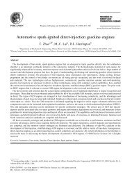
Oxyfuel <strong>Welding</strong><br />
OFW is the term to describe the group of fusion<br />
operations that burn various fuels mixed with oxygen to<br />
perform welding.<br />
The OFW processes employ several type of gases, which<br />
is the primary distinction among the members of this<br />
group.<br />
The most important OFW process is oxyacetylene<br />
welding. Filler materials are used to supply additional<br />
material to the weld zone. Flux is often used to clean the<br />
surfaces <strong>and</strong> to retard oxidation by providing inert gas<br />
shield around the weld area. It also helps in removing<br />
oxide <strong>and</strong> other impurities. Borax, is the most common<br />
flux, but sometimes other substances are added to<br />
improve its effectiveness.
Salient points about oxyacetylene welding<br />
The heat is obtained by combustion of acetylene<br />
<strong>and</strong> oxygen. Here primary combustion occurring<br />
in the inner zone gives:<br />
C H O → 2CO<br />
+ H +<br />
2<br />
2<br />
+ 2<br />
2<br />
Heat<br />
<strong>and</strong> the second reaction in the outer zone gives<br />
2CO<br />
H + 1.<br />
5O<br />
→ 2CO<br />
+ H O +<br />
+ 2<br />
2<br />
2 2<br />
Heat<br />
The maximum temperature temperature at the tip<br />
of inner cone reaches up to 3000-3500 3000 3500°C. C.<br />
Therefore, most gas welding is performed by<br />
keeping this inner zone tip just above the metal to<br />
be welded so that maximum temperature is<br />
available for welding.
Temperature distribution along the flame
A neutral flame is obtained when the ratio of is<br />
oxygen <strong>and</strong> acetylene is 1. Most gas welding<br />
operations are carried out by this flame.<br />
An oxidizing flame is obtained when this ratio is more<br />
than 1. This type of flame is not suitable for welding of<br />
steels since excess oxygen present reacts with carbon in<br />
steel <strong>and</strong> is generally used for welding of copper <strong>and</strong> its<br />
alloys.<br />
When the ratio in mixture is less than 1 a carburizing<br />
flame is obtained. In this type of flame acetylene<br />
decomposes into carbon <strong>and</strong> hydrogen <strong>and</strong> the flame<br />
temperature gets reduced. Joining operations such as<br />
brazing <strong>and</strong> soldering which require lower temperature<br />
generally use this flame.
Flame Cutting<br />
Metal is merely melted by the<br />
flame of the oxyfuel gas torch<br />
<strong>and</strong> blown away to form a gap or<br />
kerf. kerf<br />
When ferrous metal is cut,<br />
actually burning of iron takes<br />
place according to one or more of<br />
the following reactions.<br />
Fe<br />
+<br />
O<br />
→<br />
3Fe<br />
+ 2O<br />
4 Fe + 3O<br />
2<br />
2<br />
Feo<br />
→<br />
+<br />
Fe<br />
Q<br />
3<br />
O<br />
→ 2Fe<br />
2<br />
4<br />
O<br />
+<br />
3<br />
Q<br />
+<br />
Q
Because, these reactions cannot take place below 815°C 815 C oxyfuel flame<br />
is first used to raise the metal temperature where burning can be be<br />
initiated. Then a stream of pure oxygen is added to the torch (or (or<br />
the<br />
oxygen content of the oxyfuel mixture is increased) to oxidize the<br />
iron. The liquid iron <strong>and</strong> iron oxides are then expelled from the joint<br />
by the kinetic energy of the oxygen gas stream.<br />
Low rate of heat input, <strong>and</strong> need of preheating ahead of the cut,<br />
oxyfuel produces a relatively large heat affected zone <strong>and</strong> thus<br />
associated distortion zone.<br />
The process is suitable when edge finish or tolerance is not critical. critical.<br />
Theoretically heat generated due to burning of Fe is sufficient to<br />
continue cutting however due to losses additional heat supply is<br />
needed. If the work is already hot due from the other processes,<br />
supply of oxygen through a small diameter pipe is needed to continue continue<br />
cut. This is called Oxygen Lance Cutting. A workpiece temperature of<br />
1200°C 1200 C is needed to sustain the cutting.<br />
Low carbon steel from 5 to 75 mm can be cut.
Cracks (figure ( figure)<br />
<strong>Welding</strong> Defects<br />
– This causes significant reduction in the strength of weldment. weldment.<br />
<strong>Welding</strong> cracks are caused by embrittlement or low ductility<br />
of the weld <strong>and</strong>/or base metal combined with high restraint<br />
during contraction.<br />
Cavities<br />
– These includes porosity <strong>and</strong> shrinkage voids.<br />
Solid inclusions<br />
– These are metallic or non-metallic non metallic solid material particles<br />
entrapped in the weld metal. The most common form is slag<br />
inclusion or metallic oxides.<br />
Incomplete fusion (figure ( figure)<br />
– A similar defect is lack of penetration.<br />
Imperfect shape (figure ( figure)<br />
Miscellaneous defects like arc strike, excessive spatter
Various forms of <strong>Welding</strong> Cracks<br />
Several form incomplete fusion
Solid / Liquid State Bonding<br />
Low temperature joining methods are used when<br />
the metal to be joined cannot withst<strong>and</strong> high<br />
temperature, or intricate sections are to be joined,<br />
or dissimilar metals are to be joined, or<br />
weldability of material is poor.<br />
In these methods, the gap between the metal<br />
pieces to be joined is filled with molten filler<br />
material after heating the base metal. Melting<br />
point of filler material is much lower than base<br />
metals.<br />
The bonding is not due to melting of parent metal<br />
<strong>and</strong> fusion.
Filler material is drawn into the gap between the<br />
metal pieces to be joined by capillary action <strong>and</strong> the<br />
bond formation is initiated when the molten filer<br />
metal comes under intimate contact with the solid<br />
surface as in solid state welding.<br />
The nature of bond formed is much complex here,<br />
<strong>and</strong> invariably there is some degree of intersolubility<br />
between filler <strong>and</strong> base metals.<br />
This inter-diffusion inter diffusion at the base metal surface <strong>and</strong><br />
resulting alloy has a strength which is very close to<br />
that the base metal.
For a good joint strength the<br />
liquid filler metal; must flow into<br />
the gap between the metal pieces<br />
to be joined <strong>and</strong> cover the entire<br />
surface area, without gaps or blow<br />
holes. The following usually<br />
insures good bonding:<br />
– Clean base metal surfaces<br />
– Maintain optimum gap<br />
– Heat the joining area above melting<br />
temperature of the filler material<br />
– Use fluxes for welding of base metal<br />
surfaces.<br />
Joint strength is sensitive to the<br />
gap <strong>and</strong> there exists an optimum<br />
gap for a filler material.
Brazing<br />
Brazing methods<br />
(a) Torch <strong>and</strong><br />
filler rods<br />
(b) Ring of filler<br />
metal at<br />
entrance of<br />
gap<br />
(c) Foil of filler<br />
metal between<br />
flat part<br />
surfaces
In brazing the joint is made by heating the<br />
base metal red hot <strong>and</strong> filling the gap with<br />
molten metal whose melting temperature is<br />
typically above 450°C 450 C but below melting<br />
temperature o base metal. The filler metals<br />
are generally copper alloys. Cu-Zn Cu Zn <strong>and</strong> Cu- Cu<br />
Ag alloys are used for brazing because they<br />
form alloy with iron <strong>and</strong> have good<br />
strength.<br />
Various brazing joints are shown in figure.<br />
figure
(a) Conventional butt<br />
(b) Scarf joint<br />
(c) Stepped joint<br />
(d) Increased crossest ion<br />
(a) Conventional Lap<br />
(b) Cylindrical part<br />
(c) S<strong>and</strong>wiched part<br />
(d) Use of sleeve
Common braze metal families
Soldering<br />
Soldering is very similar to brazing except that<br />
filler material is usually a lead-tin lead tin based alloy<br />
which has much lower strength <strong>and</strong> melting<br />
temperature around 250°C. 250 C.<br />
In this process less alloying action between base<br />
metal <strong>and</strong> filler material as compared to brazing<br />
takes place hence the strength of joint is lesser.<br />
It is carried out using electrical resistance heating.
Joints in Soldering<br />
(a) Flat lock seam (b) Bolted or riveted joint (c) Copper<br />
pipe fitting (d) Crimping of cylindrical lap joint.
(a) Crimped lead<br />
wire PC board<br />
(b) Plated through<br />
hole on PC<br />
board to<br />
maximize<br />
solder contact<br />
area<br />
(c) Hooked wire<br />
on flat<br />
terminals<br />
(d) Twisted wires
Some common solder alloy<br />
compositions
Comparison of welding processes