Solar Photo Voltaic Switchgear Solutions - Electrium
Solar Photo Voltaic Switchgear Solutions - Electrium
Solar Photo Voltaic Switchgear Solutions - Electrium

You also want an ePaper? Increase the reach of your titles
YUMPU automatically turns print PDFs into web optimized ePapers that Google loves.
1<br />
1<br />
2<br />
2 23<br />
2<br />
4 3<br />
4 45<br />
6 5<br />
6<br />
1<br />
2<br />
3<br />
4<br />
5<br />
6<br />
A<br />
B<br />
C<br />
D<br />
E<br />
F<br />
G<br />
I<br />
A<br />
A<br />
B<br />
C<br />
B<br />
CD<br />
D<br />
E<br />
E<br />
F<br />
G F<br />
G<br />
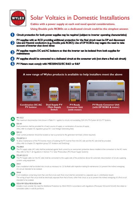
<strong>Solar</strong> <strong>Voltaic</strong>s in Domestic Installations<br />
Cables with a power supply at each end need special considerations.<br />
Using Double pole RCBOs on a dedicated circuit could be the simplest answer.<br />
Circuit protection for both power supplies may be required (subject to inverter operating characteristics)<br />
A<br />
PV supplies with an RCD providing additional protection for the final circuit must be DP and disconnect<br />
B<br />
Line and Neutral conductors (e.g. Double pole RCBO). Use of DP RCBOs may negate the need to take<br />
account of inverter shut down times<br />
B<br />
C<br />
PV supplies require DC and AC Isolators so that the inverter can be isolated from both supplies for<br />
maintenance C<br />
D<br />
PV supplies should be connected to a dedicated circuit at the consumer unit (not share a final sub circuit)<br />
E<br />
PV Meters must comply with MID2004/22/EC B&D or B&F<br />
F<br />
G<br />
A new range of Wylex products is available to help installers meet the above<br />
I<br />
I<br />
I<br />
Combination DC/AC<br />
PV Isolator<br />
Dual Supply PV<br />
/Main Supply<br />
Switch<br />
PV Ready<br />
Consumer Unit<br />
(with meter)<br />
PV Ready Consumer Unit<br />
(with DP RCBO & meter)<br />
411.3.2.2<br />
The maximum disconnection time shown in Table 41.1 applies to circuits not exceeding 32A. 0.4s TN System & 0.2s TT Systems.<br />
551.4.1<br />
Fault protection shall be provided for of each source of supply or combination of sources of supply.<br />
(Also, refer to chapter 55, regulation group 551- Low Voltage Generating Sets)<br />
551.5.1<br />
Over current protection should be located as near as practical to the generator terminals (where required).<br />
712.537.2.1.1<br />
To allow maintenance of the PV Inverter, means of isolating the PV inverter from the DC side and the AC side shall be provided.<br />
(Also, refer to chapter 53, regulation group 537- Isolation and Switching)<br />
712.434.1<br />
The PV supply cable (AC side) shall be protected against fault current by an overcurrent protective device installed at the connection to the AC mains.<br />
Also, refer to Part 7, all regulations in Section 712- <strong>Solar</strong> <strong>Photo</strong>voltaic (PV) Power Supply Systems)<br />
712.411.3.2.1.1<br />
The PV Supply cable (on the AC side) shall be connected to the supply side of the protective device for automatic disconnection of circuits supplying<br />
current-using equipment.<br />
314.1<br />
Every installation shall be divided into circuits as necessary to: (ii) facilitate safe inspection testing & maintenance (vi) prevent the indirect energising<br />
of a circuit intended to be isolated.<br />
314.4<br />
In an installation comprising more than one final circuit, each final circuit shall be connected to a separate way in a distribution board.<br />
The wiring of each final circuit shall be electrically separate from that of every other final circuit, so as to prevent the indirect energising of a final circuit<br />
intended to be isolated.<br />
522.6.101 522.6.102 & 522.6.103<br />
Installers must consider the need for Additional Protection by 30mA RCD in accordance with regulations (Previously 522.6.6 & 522.6.8) that relate to<br />
concealed cables in walls & partitions.