

ProjectPro 119 Airless Sprayer - Wagner Australia
ProjectPro 119 Airless Sprayer - Wagner Australia
ProjectPro 119 Airless Sprayer - Wagner Australia

You also want an ePaper? Increase the reach of your titles
YUMPU automatically turns print PDFs into web optimized ePapers that Google loves.
PP<strong>119</strong><br />
Figure 23 - Pump section replacement<br />
instructions<br />
Kit Part Number 0418716<br />
Danger<br />
Always wear protective eye wear while servicing the pump. Be sure to follow the Pressure Relief Procedure when shutting<br />
the unit down for any purpose, including servicing or adjusting. After performing the Pressure Relief Procedure, be sure to<br />
unplug the unit before servicing or adjusting. Area must be free of solvents and paint fumes.<br />
Disassembly of the Pump Section<br />
1. Remove the suction set.<br />
2. Remove the front cover and the three screws that secure it<br />
using a T20 Torx head driver.<br />
3. Remove the yoke screw (1) and washer (2) that secures the<br />
dowel pin (3). The dowel pin connects the yoke (4) to the<br />
piston (5).<br />
4. Using a pliers, pull the dowel pin out.<br />
5. Inspect the yoke assembly and piston. In order to remove all<br />
the necessary parts, the piston must not be in the bottom<br />
dead center position. If the piston is at the bottom of the<br />
stroke, install the front cover and screws, turn the pump on<br />
briefly to index the piston, unplug the unit, and repeat step 2.<br />
6. Unscrew and remove the inlet valve assembly (6).<br />
7. Remove the piston assembly by pushing down on the piston<br />
near the yoke.<br />
8. Unscrew and remove the top nut (7) using and adjustable<br />
wrench.<br />
9. Remove the worn seals using a flat head screwdriver or punch.<br />
Remove the top seal (8) from the top and the bottom seal (9)<br />
from the bottom by pressing against the side of the seal and<br />
popping it out. Be sure not to scratch the housing where the<br />
seals are located.<br />
10. Clean the area where the new seals are to be installed.<br />
Assembly of the Pump Section<br />
1. Lubricate the new top seal (8) with Separating Oil or light<br />
household oil and by hand place the seal (cup side of seal<br />
down) into the top port of the housing.<br />
2. Place a small amount of bearing grease on the threads of the<br />
top nut (7). Place the top nut into the top of the housing and<br />
tighten with an adjustable wrench. This will drive the top seal<br />
into the correct position.<br />
3. Turn the pump upside down. Lubricate the seal on the piston/<br />
seal assembly (5, 9) similar to the top seal. Place the piston/<br />
seal assembly into the bottom of the housing.<br />
i<br />
DO NOT attempt to remove the bottom seals from the<br />
new piston.<br />
4. Insert the insertion tool (10) and thread into position to<br />
properly seat the piston/seal. Thread fully until tight. Remove<br />
the insertion tool.<br />
5. Install the new O-ring (11) on the inlet valve assembly,<br />
lubricate with Separating Oil or light household oil, thread<br />
into the bottom (inlet) of the housing, and tighten with an<br />
adjustable wrench. This will drive the bottom seal into the<br />
correct position.<br />
6. Align the piston (5) with the yoke (4). Be careful not to<br />
damage the piston.<br />
7. Apply a bearing grease to the holes in the yoke where the<br />
dowel (3) is inserted.<br />
8. Install the dowel pin (3) to connect the yoke to the piston. The<br />
piston may have to be moved up or down to do this. The inlet<br />
valve may need to be removed again to move the piston.<br />
12<br />
9. Install the yoke screw (1) and washer (2) to secure the dowel<br />
pin.<br />
10. Turn pump right side up and apply a few drops of Separating<br />
Oil or light household oil between the top nut (7) and piston<br />
(5). This will prolong the seal life.<br />
11. Install front cover and three (3) screws.<br />
12. Install the inlet valve assembly. Install the suction set.<br />
Danger<br />
If the supply cord of this appliance is damaged, it<br />
must only be replaced by a repair shop appointed<br />
by the manufacturer, because special purpose tools<br />
are required.<br />
Do not connect the blue or brown wire to the earth<br />
terminal of the plug! The wires in this mains lead<br />
are coloured in accordance with the following code:<br />
Danger<br />
blue = live brown = live<br />
As the colours of the wires in the mains lead of this appliance<br />
may not correspond with the coloured markings identifying the<br />
terminals in your plug, proceed as follows:<br />
• Should the moulded plug have to be replaced, never re-use<br />
the defective plug or attempt to plug it into a different 13A<br />
socket. This could result in an electric shock.<br />
• Should it be necessary to exchange the fuse in the plug only<br />
use fuses approved by ASTA in accordance with BS 1362. Ten<br />
(10) Amp fuses may be used.<br />
• To ensure that the fuse and fuse carrier are correctly mounted,<br />
please observe the provided markings or colour coding in the<br />
plug.<br />
• After changing the fuse, always make sure that the fuse<br />
carrier is correctly inserted. Without the fuse carrier, it is not<br />
permissible to use the plug.<br />
• The correct fuses and fuse carriers are available from your local<br />
electrical supplies stocklist.<br />
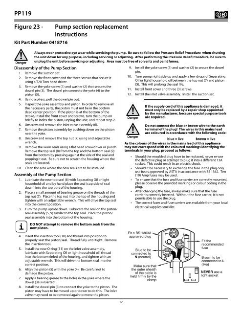
Fit a BS 1363A<br />
approved plug<br />
Blue to be<br />
connected to<br />
N (neutral)<br />
Make sure that<br />
the outer sheath<br />
of the cable is<br />
held firmly by the<br />
clamp<br />
Fit the<br />
recommended<br />
fuse<br />
Brown to be<br />
connected to L<br />
(live)<br />
NEVER use a<br />
light socket