the magazine of astounding sound
the magazine of astounding sound
the magazine of astounding sound

Create successful ePaper yourself
Turn your PDF publications into a flip-book with our unique Google optimized e-Paper software.
Buddhafying <strong>the</strong><br />
Dyna FM-3<br />
By John “Buddha” Camille<br />
You guys who know Buddha also know I let a djinni<br />
out <strong>of</strong> <strong>the</strong> bottle when I asked him for a few simple<br />
ideas on modding a little ’ol FM-3. Hang on to your<br />
hats with this one bottleheads, by <strong>the</strong> time Buddha gets<br />
through with you, you’ll not only have <strong>the</strong> meanest<br />
FM-3 in town, you’ll have <strong>the</strong> cleanest tubes too. - Doc<br />
B.<br />
Dear Dr. R sub g (R g ),<br />
Was very amused at <strong>the</strong> third issue <strong>of</strong> “V”. Your new<br />
subtitle bears out <strong>the</strong> caliber <strong>of</strong> your readership. (Buddha<br />
is <strong>of</strong> course referring to <strong>the</strong> unending string <strong>of</strong><br />
corrections I got regarding that dumb grid resistor I<br />
left on <strong>the</strong> output tube in <strong>the</strong> Blues Master article - B.)<br />
The FM-3 has turned into a real challenge. My thoughts<br />
<strong>of</strong> hot-rodding <strong>the</strong> tuner and IF strips were dashed by<br />
<strong>the</strong> wide open construction <strong>of</strong> <strong>the</strong> unit. Using higher<br />
g m tubes for <strong>the</strong> mixer and IF strips was not possible<br />
due to <strong>the</strong> lack <strong>of</strong> shielding.<br />
Above a certain total gain<br />
point <strong>the</strong> RF-IF strip takes <strong>of</strong>f<br />
and will oscillate at around<br />
1 0 7<br />
MHz, <strong>the</strong> tenth harmonic <strong>of</strong><br />
<strong>the</strong> IF. The feedback path is<br />
primarily through radiation<br />
from <strong>the</strong> last IF stage back<br />
through <strong>the</strong> RF stage grid circuit,<br />
in concert with direct<br />
conduction through <strong>the</strong> B+<br />
and heater circuits. There is<br />
also a lot <strong>of</strong> direct radiation<br />
above chassis from tubes and<br />
<strong>the</strong> mickey mouse tube and IF<br />
can shields. This problem prevented<br />
me from getting 60 dB<br />
plus <strong>of</strong> limiting on noise alone<br />
by using hotter tubes in <strong>the</strong> IF.<br />
I did achieve a happy balance <strong>of</strong> gains between <strong>the</strong> RF<br />
and IF that permits better limiting, slightly increased<br />
total gain, and much better noise figure with <strong>the</strong> 6DJ8<br />
front end. Several college stations thirty to forty miles<br />
way now come in full quieting with a 3 foot clip lead<br />
antenna.<br />
Eventually I hope to fully shield <strong>the</strong> RF section and<br />
possibly <strong>the</strong> bottom <strong>of</strong> <strong>the</strong> IF with proper interstage<br />
shielding and tons <strong>of</strong> bulkhead feed-throughs. I did<br />
cheat and use button mica caps on <strong>the</strong> RF board while<br />
trying to calm oscillations. These caps get <strong>the</strong> RF <strong>of</strong>f <strong>of</strong><br />
<strong>the</strong> lower cathode and upper grid and <strong>of</strong> course increased<br />
RF gain considerably. This required lowering<br />
<strong>the</strong> gain on <strong>the</strong> IF strip. This was done by lowering<br />
plate and screen voltages, which had <strong>the</strong> added benefit<br />
<strong>of</strong> providing better limiting. Virtually any signal<br />
will now produce a limited 4V pk-pk signal on <strong>the</strong> plate<br />
<strong>of</strong> V-6. A slight bit <strong>of</strong> AM’ing is still visible on positive<br />
peaks, however. Before modding, AM was significant<br />
on both positive and negative peaks. The beast is really<br />
starting to <strong>sound</strong> solid.<br />
I have not had time to redo <strong>the</strong> first audio stage, V-7,<br />
and <strong>the</strong> audio output stage V-72. Plan to use a 5687<br />
for V-7 and 12B4’s for V-72. Of course, C4S’s will be<br />
used for cathode and plate follower feedback on <strong>the</strong><br />
output. Will probably change <strong>the</strong> volume control to a<br />
6dB stepped attenuator for better high frequency response.<br />
The present 19,38 and 67kHz attenuation really sucks.<br />
Plan to use plenty <strong>of</strong> LC traps and filtering here, along<br />
with a proper de-emphasis filter. May need a cathode<br />
follower to drive <strong>the</strong>se filters properly. The present system<br />
has a lot <strong>of</strong> 38 kHz on <strong>the</strong> output and tons <strong>of</strong> 67<br />
kHz SCA on some stations.<br />
Hum has always been a problem on my unit. Got rid <strong>of</strong><br />
about 95% <strong>of</strong> it with additional filtering and direct<br />
wiring <strong>the</strong> primary power. Putting 120 VAC (to <strong>the</strong><br />
on-<strong>of</strong>f switch) within 1/2 inch <strong>of</strong> <strong>the</strong> first audio stage<br />
is not very cool. Am planning to eventually move <strong>the</strong><br />
power supply <strong>of</strong>f chassis and DC everything in a large<br />
audio visual console I had built in <strong>the</strong> Phillipines back<br />
in <strong>the</strong> 60’s. The wood, Nara, is too hard to work so I’ll<br />
have to stick with <strong>the</strong> heavily modded stuff that will<br />
fit <strong>the</strong> holes on <strong>the</strong> cabinet work.<br />
Tweaks that might be applicable to <strong>the</strong> experiexperimenter RF-IF Tube Shielding<br />
The original tube shields are tube killers. I had replaced<br />
<strong>the</strong> tin can shields with IERC style shields when <strong>the</strong><br />
unit was built back in <strong>the</strong> early 60’s. All tubes still have<br />
plenty <strong>of</strong> emmision with probably 100K hours <strong>of</strong> use.<br />
These shields are still hot with RF however, as <strong>the</strong> original<br />
ground strip corrodes pretty quick. A better answer<br />
is my combination tube shield/microphonic attenuator.<br />
This process should be used on all tubes in<br />
<strong>the</strong> set, especially <strong>the</strong> RF-IF tubes. Some folks might<br />
not like <strong>the</strong> sonics when this technique is used on <strong>the</strong><br />
audio tubes because much <strong>of</strong> <strong>the</strong> reverb is lost...<br />
Procedure<br />
1 Select a new tube that checks way over good.<br />
2 Wire brush pins until shiny with a gun bore<br />
brush chucked up in a drill motor or Dremel tool.<br />
Practice on an old tube until you figure it out.<br />
3 Wash tube thoroughly with tooth brush and 409.<br />
Rinse and blow dry. Do not touch pins with fin-<br />
gers again. We’re talking clean room plastic<br />
gloves here (food handler gloves are cheaper)<br />
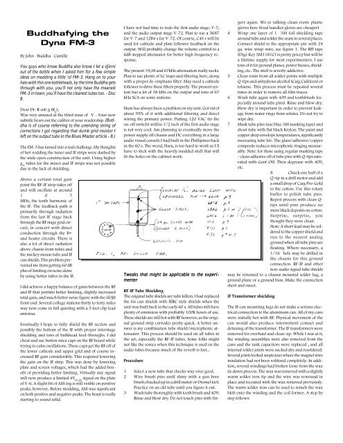
4 Wrap one layer <strong>of</strong> 1” 3M foil shielding tape<br />
around tube and solder <strong>the</strong> seam in several places.<br />
Connect shield to <strong>the</strong> appropriate pin with 24<br />
ga. wire wrap wire, see figure 1. The RFI tape<br />
(Digi-Key 3M1181C) is pretty pricey but will be<br />
a lifetime supply for most experimenters. I use<br />
tons <strong>of</strong> it for ground planes, power busses, shielding,<br />
etc. The stuff is severly addictive.<br />
5 Clean rosin from all solder points with multiple<br />
Q-tips and anhydrous alcohol (Caig Caikleen) or<br />
toluene. This process must be repeated several<br />
times in order to remove all film traces.<br />
6 Wash tube again with 409 and toothbrush (especially<br />
around tube pins). Rinse and blow dry.<br />
Blow dry is important in order to prevent leakage<br />
from water rings from solutes. Do not try to<br />
wipe dry.<br />
7 Mask tube pins (use blue 3M masking tape) and<br />
shoot tube with flat black Krylon. The paint and<br />
copper drop envelope temperatures, significantly<br />
increasing tube life. The glass/adhesive/copper<br />
composite reduces microphonic ringing measurably.<br />
Note: for those using regular masking tape<br />
- clean adhesive <strong>of</strong>f <strong>of</strong> tube pins with Q-tips saturated<br />
with Go<strong>of</strong>-Off. Then degrease with 409,<br />
etc.<br />
8 Chuck one half <strong>of</strong> a<br />
Q-tip in a drill motor and add<br />
a small drop <strong>of</strong> Caig Pro-Gold<br />
to <strong>the</strong> cotton. Use this rotary<br />
buffer to polish tube pins.<br />
Repest process with clean Qtips<br />
until pins produce no<br />
more black deposits on cotton.<br />
Surprise, surprise, you<br />
thought <strong>the</strong>y were clean.<br />
Note: A short lead may be soldered<br />
to <strong>the</strong> copper shield and<br />
run to <strong>the</strong> nearest analog<br />
ground when all tube pins are<br />
floating. Where necessary, a<br />
1/16” hole may be drilled in<br />
<strong>the</strong> chassis for this ground<br />
connection. RF-IF and o<strong>the</strong>r<br />
non-audio signal tube shields<br />
may be returned to a chassis mounted solder lug, a<br />
ground plane or a ground buss. Make <strong>the</strong> connection<br />
short and sweet.<br />
IF Transformer shielding<br />
The IF can mounting lugs do not make a serious electrical<br />
connection to <strong>the</strong> aluminum can. All <strong>of</strong> my cans<br />
were initially hot with RF. Physical movement <strong>of</strong> <strong>the</strong><br />
can would also produce intermittent contact and<br />
detuning <strong>of</strong> <strong>the</strong> transformer. The IF transformers were<br />
removed for overhaul and clean-up. While I was at it,<br />
<strong>the</strong> winding assemblies were also removed from <strong>the</strong><br />
cans and <strong>the</strong> tank capacitors were replaced , and all<br />
internal solder joints were sucked dry and resoldered.<br />
Several joints looked suspicious where <strong>the</strong> magnet wire<br />
insulation had not been volitized completely. In addition,<br />
several windings had broken loose from <strong>the</strong> wax<br />
tie down process. The wax was removed with a slightly<br />
warm solder iron tip and <strong>the</strong> wire was rewound in<br />
place and recoated with <strong>the</strong> wax removed previously.<br />
The warm solder iron can be used to remelt <strong>the</strong> wax<br />
blob onto <strong>the</strong> winding and <strong>the</strong> coil former. A step by<br />
step follows: