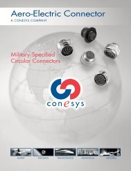
MIL-DTL-38999 Series I - Aero-Electric Connector, Inc.
MIL-DTL-38999 Series I - Aero-Electric Connector, Inc.
MIL-DTL-38999 Series I - Aero-Electric Connector, Inc.

You also want an ePaper? Increase the reach of your titles
YUMPU automatically turns print PDFs into web optimized ePapers that Google loves.
Performance Specifications<br />
Operating Temperature Range<br />
Finish B: -65°C to +175°C (-85°F to +347°F)<br />
Finish F: -65°C to +200°C (-85°F to +392°F<br />
Finish A: -65°C to +150°C (-85°F to +302°F)<br />
Material and Plating Data (Finish)<br />
B – aluminum shell, olive drab cadmium over nickel base<br />
F – aluminum shell, electroless nickel finish<br />
A– aluminum shell, silver to light iridescent yellow color<br />
(bright) cadmium over electroless nickel<br />
Corrosion Resistance<br />
Finishes A and B withstand 500-hour salt spray.<br />
Finish F withstands 48-hour salt spray.<br />
Durability<br />
Minimum of 500 mating cycles<br />
Environmental Seal<br />
Wired, mated connectors with specified accessories<br />
attached, shall meet the altitude-immersion test specified in<br />
<strong>MIL</strong>-<strong>DTL</strong>-<strong>38999</strong>.<br />
Fluid Resistance<br />
<strong>Connector</strong>s resist specified immersions in <strong>MIL</strong>-PRF-7808,<br />
<strong>MIL</strong>-PRF-23699, <strong>MIL</strong>-PRF-5606, M2-V Chevron oil, Coolanol<br />
25, <strong>MIL</strong>-<strong>DTL</strong>-83133 (JP-8), <strong>MIL</strong>-<strong>DTL</strong>-5624 (JP-4, JP-5),<br />
SAE-AMS1424 Type I, and other solvents and cleaning agents.<br />
Shell-to-Shell Conductivity<br />
● Finish F = 1.0 millivolt maximum potential drop<br />
● Finishes A and B = 2.5 millivolts maximum potential drop<br />
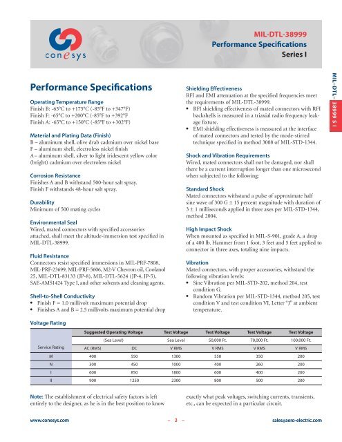
Voltage Rating<br />
Service Rating<br />
<strong>MIL</strong>-<strong>DTL</strong>-<strong>38999</strong><br />
Performance Specifications<br />
<strong>Series</strong> I<br />
Shielding Effectiveness<br />
RFI and EMI attenuation at the specified frequencies meet<br />
the requirements of <strong>MIL</strong>-<strong>DTL</strong>-<strong>38999</strong>.<br />
● RFI shielding effectiveness of mated connectors with RFI<br />
backshells is measured in a triaxial radio frequency leakage<br />
fixture.<br />
● EMI shielding effectiveness is measured at the interface<br />
of mated connectors and tested by the mode-stirred<br />
technique specified in method 3008 of <strong>MIL</strong>-STD-1344.<br />
Shock and Vibration Requirements<br />
Wired, mated connectors shall not be damaged, nor shall<br />
there be a current interruption longer than one microsecond<br />
when subjected to the following:<br />
Standard Shock<br />
Mated connectors withstand a pulse of approximate half<br />
sine wave of 300 G ± 15 percent magnitude with duration of<br />
3 ± 1 milliseconds applied in three axes per <strong>MIL</strong>-STD-1344,<br />
method 2004.<br />
High Impact Shock<br />
When mounted as specified in <strong>MIL</strong>-S-901, grade A, a drop<br />
of a 400 lb. Hammer from 1 foot, 3 feet and 5 feet applied to<br />
connector in three axes, totaling nine impacts.<br />
Vibration<br />
Mated connectors, with proper accessories, withstand the<br />
following vibration levels:<br />
● Sine Vibration per <strong>MIL</strong>-STD-202, method 204, test<br />
condition G.<br />
● Random Vibration per <strong>MIL</strong>-STD-1344, method 205, test<br />
condition V and test condition VI, Letter “J” at ambient<br />
temperature.<br />
Suggested Operating Voltage Test Voltage Test Voltage Test Voltage Test Voltage<br />
(Sea Level) Sea Level 50,000 Ft. 70,000 Ft. 100,000 Ft.<br />
AC (RMS) DC V RMS V RMS V RMS V RMS<br />
M 400 550 1300 550 350 200<br />
N 300 450 1000 400 260 200<br />
I 600 850 1800 600 400 200<br />
II 900 1250 2300 800 500 200<br />
Note: The establishment of electrical safety factors is left<br />
entirely to the designer, as he is in the best position to know<br />
exactly what peak voltages, switching currents, transients,<br />
etc., can be expected in a particular circuit.<br />
www.conesys.com – 3 –<br />
sales@aero-electric.com<br />
<strong>MIL</strong>–<strong>DTL</strong>– <strong>38999</strong> S I