Gas insulated MV circuit-breakers 12 ... 40.5 kV - 630 ... - Arianbc.net
Gas insulated MV circuit-breakers 12 ... 40.5 kV - 630 ... - Arianbc.net
Gas insulated MV circuit-breakers 12 ... 40.5 kV - 630 ... - Arianbc.net
You also want an ePaper? Increase the reach of your titles
YUMPU automatically turns print PDFs into web optimized ePapers that Google loves.
74<br />
7 ELECTRICAL CIRCUIT DIAGRAM<br />
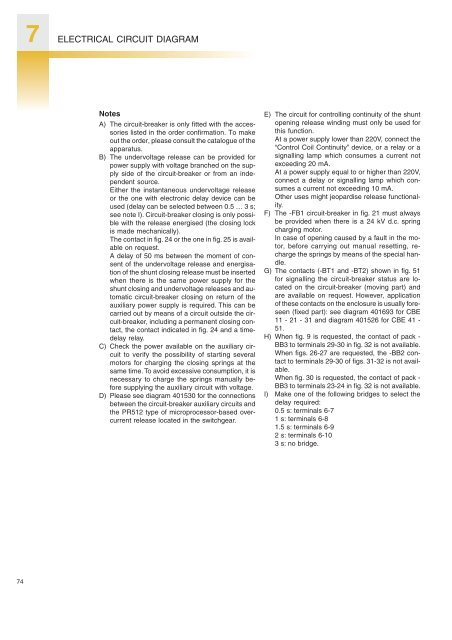
Notes<br />
A) The <strong>circuit</strong>-breaker is only fitted with the accessories<br />
listed in the order confirmation. To make<br />
out the order, please consult the catalogue of the<br />
apparatus.<br />
B) The undervoltage release can be provided for<br />
power supply with voltage branched on the supply<br />
side of the <strong>circuit</strong>-breaker or from an independent<br />
source.<br />
Either the instantaneous undervoltage release<br />
or the one with electronic delay device can be<br />
used (delay can be selected between 0.5 … 3 s;<br />
see note I). Circuit-breaker closing is only possible<br />
with the release energised (the closing lock<br />
is made mechanically).<br />
The contact in fig. 24 or the one in fig. 25 is available<br />
on request.<br />
A delay of 50 ms between the moment of consent<br />
of the undervoltage release and energisation<br />
of the shunt closing release must be inserted<br />
when there is the same power supply for the<br />
shunt closing and undervoltage releases and automatic<br />
<strong>circuit</strong>-breaker closing on return of the<br />
auxiliary power supply is required. This can be<br />
carried out by means of a <strong>circuit</strong> outside the <strong>circuit</strong>-breaker,<br />
including a permanent closing contact,<br />
the contact indicated in fig. 24 and a timedelay<br />
relay.<br />
C) Check the power available on the auxiliary <strong>circuit</strong><br />
to verify the possibility of starting several<br />
motors for charging the closing springs at the<br />
same time. To avoid excessive consumption, it is<br />
necessary to charge the springs manually before<br />
supplying the auxiliary <strong>circuit</strong> with voltage.<br />
D) Please see diagram 401530 for the connections<br />
between the <strong>circuit</strong>-breaker auxiliary <strong>circuit</strong>s and<br />
the PR5<strong>12</strong> type of microprocessor-based overcurrent<br />
release located in the switchgear.<br />
E) The <strong>circuit</strong> for controlling continuity of the shunt<br />
opening release winding must only be used for<br />
this function.<br />
At a power supply lower than 220V, connect the<br />
“Control Coil Continuity” device, or a relay or a<br />
signalling lamp which consumes a current not<br />
exceeding 20 mA.<br />
At a power supply equal to or higher than 220V,<br />
connect a delay or signalling lamp which consumes<br />
a current not exceeding 10 mA.<br />
Other uses might jeopardise release functionality.<br />
F) The -FB1 <strong>circuit</strong>-breaker in fig. 21 must always<br />
be provided when there is a 24 <strong>kV</strong> d.c. spring<br />
charging motor.<br />
In case of opening caused by a fault in the motor,<br />
before carrying out manual resetting, recharge<br />
the springs by means of the special handle.<br />
G) The contacts (-BT1 and -BT2) shown in fig. 51<br />
for signalling the <strong>circuit</strong>-breaker status are located<br />
on the <strong>circuit</strong>-breaker (moving part) and<br />
are available on request. However, application<br />
of these contacts on the enclosure is usually foreseen<br />
(fixed part): see diagram 401693 for CBE<br />
11 - 21 - 31 and diagram 401526 for CBE 41 -<br />
51.<br />
H) When fig. 9 is requested, the contact of pack -<br />
BB3 to terminals 29-30 in fig. 32 is not available.<br />
When figs. 26-27 are requested, the -BB2 contact<br />
to terminals 29-30 of figs. 31-32 is not available.<br />
When fig. 30 is requested, the contact of pack -<br />
BB3 to terminals 23-24 in fig. 32 is not available.<br />
I) Make one of the following bridges to select the<br />
delay required:<br />
0.5 s: terminals 6-7<br />
1 s: terminals 6-8<br />
1.5 s: terminals 6-9<br />
2 s: terminals 6-10<br />
3 s: no bridge.


