

Understanding Polarization - Semrock
Understanding Polarization - Semrock
Understanding Polarization - Semrock

Create successful ePaper yourself
Turn your PDF publications into a flip-book with our unique Google optimized e-Paper software.
c direction is markedly different than that along the a and b directions, thus leading to a different<br />
index of refraction for light polarized along this direction.<br />
a<br />
c<br />
b<br />
O<br />
Ca<br />
Ca<br />
O<br />
O<br />
C<br />
C<br />
O<br />
O<br />
O Ca<br />
Ca<br />
O<br />
O<br />
O C<br />
O C<br />
O<br />
Other materials are nominally isotropic, but when they are bent or deformed in some way, they<br />
become anisotropic and therefore exhibit birefringence. This effect is widely used to study the<br />
mechanical properties of materials with optics.<br />
4. Effects of reflection and transmission on polarization<br />
The polarization of light reflected and transmitted at an interface between two media or at a<br />
thin-film multilayer coating can be altered dramatically. These two cases are considered below.<br />
a. <strong>Polarization</strong> dependence of light reflected or transmitted at an interface<br />
When light is incident on an interface between two different media with different indexes of<br />
refraction, some of the light is reflected and some is transmitted. When the angle of incidence is<br />
not normal, different polarizations are reflected (and transmitted) by different amounts. This<br />
dependence was first properly described by Fresnel, and hence it is often called “Fresnel<br />
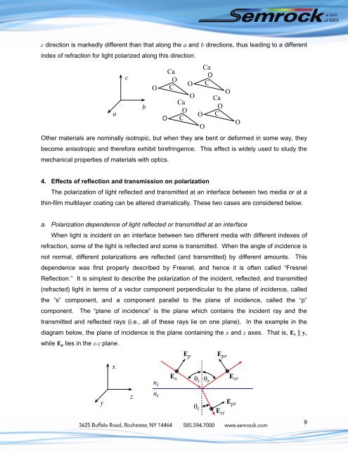
Reflection.” It is simplest to describe the polarization of the incident, reflected, and transmitted<br />
(refracted) light in terms of a vector component perpendicular to the plane of incidence, called<br />
the “s” component, and a component parallel to the plane of incidence, called the “p”<br />
component. The “plane of incidence” is the plane which contains the incident ray and the<br />
transmitted and reflected rays (i.e., all of these rays lie on one plane). In the example in the<br />
diagram below, the plane of incidence is the plane containing the x and z axes. That is, Es || y,<br />
while Ep lies in the x-z plane.<br />
y<br />
x<br />
z<br />
n i<br />
n t<br />
E s<br />
E p<br />
i<br />
t<br />
r<br />
E pr<br />
E st<br />
O<br />
E sr<br />
E pt<br />
9