WATER SUPPLY CODE - Water Services Association of Australia
WATER SUPPLY CODE - Water Services Association of Australia
WATER SUPPLY CODE - Water Services Association of Australia
Create successful ePaper yourself
Turn your PDF publications into a flip-book with our unique Google optimized e-Paper software.
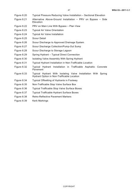
Figure 8.20 Typical Pressure Reducing Valve Installation – Sectional Elevation<br />
Figure 8.21 Alternative Above-Ground Installation – PRV on Bypass – Side<br />
Elevation<br />
Figure 8.22 PRV on Main Line With Bypass – Plan View<br />
Figure 8.23 Typical Air Valve Orientation<br />
Figure 8.24 Typical Air Valve Installation<br />
Figure 8.25 Scour Detail<br />
Figure 8.26 Scour Discharge to Approved Drainage System<br />
Figure 8.27 Scour Discharge Collection/Pump-Out Sump<br />
Figure 8.28 Scour Discharge to Storage Lagoon<br />
Figure 8.29 Spring Hydrant – Typical Direct Connection<br />
Figure 8.30 Isolating Valve Assembly With Spring Hydrant<br />
Figure 8.31 Typical Hydrant Installation in Non-Trafficable Location<br />
Figure 8.32 Typical Hydrant Installation in Trafficable Asphaltic Concrete<br />
Pavement<br />
Figure 8.33 Typical Hydrant With Isolating Valve Installation With Spring<br />
Hydrant Option in Non-Trafficable Location<br />
Figure 8.34 Typical Offsetting <strong>of</strong> Hydrants in Footway<br />
Figure 8.35 Non-Trafficable Stop Valve Surface Box<br />
Figure 8.36 Typical Trafficable Stop Valve Surface Boxes<br />
Figure 8.37 Typical Trafficable Hydrant Surface Boxes<br />
Figure 8.38 Retro-Reflective Pavement Markers<br />
Figure 8.39 Kerb Markings<br />
47<br />
COPYRIGHT<br />
WSA 03—2011-3.1


