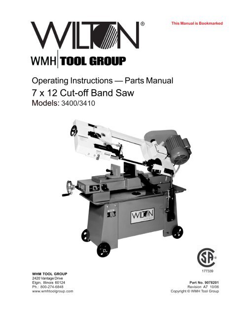
7 x 12 Cut-off Band Saw - Igor Chudov
7 x 12 Cut-off Band Saw - Igor Chudov
7 x 12 Cut-off Band Saw - Igor Chudov

You also want an ePaper? Increase the reach of your titles
YUMPU automatically turns print PDFs into web optimized ePapers that Google loves.
Operating Instructions — Parts Manual<br />
7 x <strong>12</strong> <strong>Cut</strong>-<strong>off</strong> <strong>Band</strong> <strong>Saw</strong><br />
Models: 3400/3410<br />
This Manual is Bookmarked<br />
WHM TOOL GROUP<br />
2420 Vantage Drive<br />
177339<br />
Elgin, Illinois 60<strong>12</strong>4 Part No. 9078201<br />
Ph.: 800-274-6848 Revision A7 10/06<br />
www.wmhtoolgroup.com Copyright © WMH Tool Group
Warranty and Service<br />
WMH Tool Group, Inc., warrants every product it sells. If one of our tools needs service or repair, one of our Authorized Service Centers<br />
located throughout the United States can give you quick service. In most cases, any of these WMH Tool Group Authorized Service<br />
Centers can authorize warranty repair, assist you in obtaining parts, or perform routine maintenance and major repair on your<br />
WILTON® tools. For the name of an Authorized Service Center in your area call 1-800-274-6848.<br />
MORE INFORMATION<br />
Group distributor, or visit wiltontool.com.<br />
WARRANTY<br />
WILTON products carry a limited warranty which varies in duration based upon the product. (MW = Metalworking)<br />
WHAT IS COVERED?<br />
This warranty covers any defects in workmanship or materials subject to the exceptions stated below. <strong>Cut</strong>ting tools, abrasives and<br />
other consumables are excluded from warranty coverage.<br />
WHO IS COVERED?<br />
This warranty covers only the initial purchaser of the product.<br />
WHAT IS THE PERIOD OF COVERAGE?<br />
The general WILTON warranty lasts for the time period specified in the product literature of each product.<br />
WHAT IS NOT COVERED?<br />
This warranty does not cover defects due directly or indirectly to misuse, abuse, negligence or accidents, normal wear-and-tear,<br />
improper repair or alterations, or lack of maintenance.<br />
HOW TO GET SERVICE<br />
The product or part must be returned for examination, postage prepaid, to a location designated by us. For the name of the location<br />
nearest you, please call 1-800-274-6848.<br />
You must provide proof of initial purchase date and an explanation of the complaint must accompany the merchandise. If our inspection<br />
discloses a defect, we will repair or replace the product, or refund the purchase price, at our option.<br />
We will return the repaired product or replacement at our expense unless it is determined by us that there is no defect, or that the defect<br />
resulted from causes not within the scope of our warranty in which case we will, at your direction, dispose of or return the product.<br />
In the event you choose to have the product returned, you will be responsible for the handling and shipping costs of the return.<br />
HOW STATE LAW APPLIES<br />
This warranty gives you specific legal rights; you may also have other rights which vary from state to state.<br />
LIMITATIONS ON THIS WARRANTY<br />
WMH TOOL GROUP LIMITS ALL IMPLIED WARRANTIES TO THE PERIOD OF THE LIMITED WARRANTY FOR EACH PRODUCT. EXCEPT AS<br />
STATED HEREIN, ANY IMPLIED WARRANTIES OR MERCHANTABILITY AND FITNESS ARE EXCLUDED. SOME STATES DO NOT ALLOW<br />
LIMITATIONS ON HOW LONG THE IMPLIED WARRANTY LASTS, SO THE ABOVE LIMITATION MAY NOT APPLY TO YOU.<br />
WMH TOOL GROUP SHALL IN NO EVENT BE LIABLE FOR DEATH, INJURIES TO PERSONS OR PROPERTY, OR FOR INCIDENTAL,<br />
CONTINGENT, SPECIAL, OR CONSEQUENTIAL DAMAGES ARISING FROM THE USE OF OUR PRODUCTS. SOME STATES DO NOT<br />
ALLOW THE EXCLUSION OR LIMITATION OF INCIDENTAL OR CONSEQUENTIAL DAMAGES, SO THE ABOVE LIMITATION OR EXCLUSION<br />
MAY NOT APPLY TO YOU.<br />
WMH Tool Group sells through distributors only. The specifications in WMH catalogs are given as general information and are not<br />
binding. Members of WMH Tool Group reserve the right to effect at any time, without prior notice, those alterations to parts, fittings, and<br />
accessory equipment which they may deem necessary for any reason whatsoever.
Table of Contents<br />
Cover Page .......................................................................................................................... 1<br />
Warranty................................................................................................................................ 2<br />
Table of Contents .................................................................................................................. 3<br />
General Specifications .......................................................................................................... 4<br />
Warnings ............................................................................................................................ 5-6<br />
Using the Vise.................................................................................................................... 7-9<br />
Setting Blade Guides ............................................................................................................ 9<br />
Hydraulic Feed Control........................................................................................................ 10<br />
Using Stock Stop................................................................................................................. 10<br />
Changing Blade Speeds ..................................................................................................... 11<br />
Blade Selection................................................................................................................... 11<br />
Evaluating <strong>Cut</strong>ting Eficiency ................................................................................................ 11<br />
Blade Break-in Procedures ................................................................................................. 11<br />
Starting a <strong>Cut</strong> ...................................................................................................................... 11<br />
Angle <strong>Cut</strong>s ..................................................................................................................... <strong>12</strong>-13<br />
Replacing Blades ................................................................................................................ 14<br />
Adjusting Blade Tracking ..................................................................................................... 14<br />
Blade Alignment Adjustments .............................................................................................. 15<br />
When to Adjust Blade Guides .............................................................................................. 15<br />
Replacing Blade Guides and Support Components............................................................. 16<br />
Adjust Blade for Parallelism ................................................................................................ 16<br />
Adjusting Blade Vertical ...................................................................................................... 17<br />
Test <strong>Cut</strong>ting to Verify Adjustment Accuracy ........................................................................... 17<br />
Adjusting Guide Bearings.................................................................................................... 18<br />
Replacing Guide Bearings .................................................................................................. 18<br />
Adjusting Blade Back Up Bearing ....................................................................................... 18<br />
Replacing the Drive Wheel .................................................................................................. 19<br />
Installing the Vertical <strong>Saw</strong>ing Table ...................................................................................... 19<br />
Replacing Idler Wheel or Bearings ...................................................................................... 19<br />
Servicing the Hydraulic Control Cylinder .............................................................................. 20<br />
Machine Set-up ................................................................................................................... 21<br />
Uncrating and Spotting the <strong>Saw</strong>........................................................................................... 21<br />
Electrical ............................................................................................................................. 21<br />
Changing Operating Voltage ............................................................................................... 21<br />
Installing the Coolant Kit ...................................................................................................... 22<br />
Chip Brush Replacement .................................................................................................... 22<br />
Adjusting Horizontal Stop and Motor Switch ......................................................................... 22<br />
To Replace or Adjust the Horizontal Stop ............................................................................. 22<br />
Adjusting the Motor Switch Actuator..................................................................................... 22<br />
Troubleshooting.............................................................................................................. 23-24<br />
Replacement Parts and Breakdowns ............................................................................. 25-30<br />
3
4<br />
General<br />
Specifications<br />
The Wilton Models 3400 and 3410 cut-<strong>off</strong> band saws<br />
are designed for high production cut-<strong>off</strong> work. Four cutting<br />
speeds and a hydraulic feed control allows the efficient cutting<br />
of virtually any material.<br />
A removable table also allows the saw to function as a<br />
vertical band saw.<br />
Specifications:<br />
<strong>Cut</strong>ting capacity<br />
Blade speeds<br />
Blade drive<br />
Motor<br />
Blade guides<br />
Blade size<br />
Blade wheels<br />
Dimensions (LWH)<br />
Weight<br />
Wet cutting package<br />
Vertical saw operation<br />
Table size (LW)<br />
The Model 3410 is equipped with an optional coolant<br />
system which can greatly extend blade life and speed the cutting<br />
of a variety of materials which are best cut with cutting<br />
fluids and coolants.<br />
The Model 3400 is not equipped with a coolant system.<br />
However, the coolant system is available as an add-on kit for<br />
customer installation.<br />
7 in. (178mm) round bar stock or tubing<br />
9 1/2 in. wide x 7 in. high (240 x 178mm) rectangular stock<br />
<strong>12</strong> in. wide x 1 in. high (305 x 25.4mm) flat stock<br />
3 3/4 in. wide x 6 in. high (95.3 x 150mm) at 45 degree angle<br />
80, 130, 180 and 265 SFM -- belt selectable<br />
Heat treated steel worm pinion driving a bronze<br />
worm ring gear in an oil bath<br />
3/4 HP, 1725 RPM, 115/230V, single phase, capacitor start<br />
Side: Eccentric shaft with sealed ball bearings<br />
Rear: Sealed ball bearing<br />
3/4 x .032 x 93 in.<br />
11 7/16 in. (280.56mm) diameter flanged cast iron<br />
50 x 18 x 41 in. (<strong>12</strong>70 x 457 x 1041mm) in lowered position<br />
275 lbs. (<strong>12</strong>5kg)<br />
1 gallon (4.4L) capacity tank with 3GPM (13L/M) pump -- Optional wet kit<br />
Part No. 5635500 includes tank with baffle, pump <strong>12</strong>0V/240V, hoses,<br />
flexible nozzle, shut-<strong>off</strong> valve and required electrics. This kit is delivered<br />
installed on Model 3410 saws.<br />
9 1/2 x 10 in. (241 x 254mm)
- Misuse of this machine can cause serious injury.<br />
- For safety, machine must be set up, used and serviced<br />
properly.<br />
- Read, understand and follow instructions in the<br />
operator’s and parts manual which was shipped with<br />
your machine.<br />
When setting up machine:<br />
- Always avoid using machine in damp or poorly lighted<br />
work areas.<br />
- Always be sure machine is securely anchored to the<br />
floor.<br />
- Always keep machine guards in place.<br />
- Always put start switch in OFF“ position before<br />
plugging in machine.<br />
When using machine:<br />
- Never operate with machine guards missing.<br />
- Always wear safety glasses with side shields (See<br />
ANSI Z87.1)<br />
- Never wear loose clothing or jewelry.<br />
- Never overreach — you may slip and fall into the<br />
machine.<br />
- Never leave machine running while away from it.<br />
1. Always wear protective eye wear when operating<br />
machinery. Eye wear shall be impact resistant, protective<br />
safety glasses with side shields which comply with ANSI<br />
Z87.1 specifications. Use of eye wear which does not<br />
comply with ANSI Z87.1 specifications could result in<br />
severe injury from breakage of eye protection.<br />
2. Wear proper apparel. No loose clothing or<br />
jewelry which can get caught in moving parts. Rubber<br />
soled footwear is recommended for best footing.<br />
3. Do not overreach. Failure to maintain proper<br />
working position can cause you to fall into the machine or<br />
cause your clothing to get caught — pulling you into the<br />
machine.<br />
4. Keep guards in place and in proper working<br />
order. Do not operate the machine with guards removed.<br />
5. Avoid dangerous working environments. Do not<br />
use stationary machine tools in wet or damp locations.<br />
Keep work areas clean and well lit. Special electrics<br />
should be used when working on flammable materials.<br />
6. Avoid accidental starts by being sure the start<br />
switch is OFF” before plugging in the machine.<br />
7. Never leave the machine running while unattended.<br />
Machine shall be shut <strong>off</strong> whenever it is not in<br />
operation.<br />
8. Disconnect electrical power before servicing.<br />
Whenever changing accessories or general maintenance<br />
is done on the machine, electrical power to the machine<br />
must be disconnected before work is done.<br />
- Always shut <strong>off</strong> the machine when not in use.<br />
When servicing machine:<br />
- Always unplug machine from electrical power while<br />
servicing.<br />
- Always follow instructions in operators and parts<br />
manual when changing accessory tools or parts.<br />
- Never modify the machine without consulting Wilton<br />
Corporation.<br />
You — the stationary power tool user — hold the<br />
key to safety.<br />
Read and follow these simple rules for best<br />
results and full benefits from your machine. Used<br />
properly, Wilton’s machinery is among the best in<br />
design and safety. However, any machine used<br />
improperly can be rendered inefficient and unsafe. It is<br />
absolutely mandatory that those who use our products<br />
be properly trained in how to use them correctly. They<br />
should read and understand the Operators and Parts<br />
Manual as well as all labels affixed to the machine.<br />
Failure in following all of these warnings can cause<br />
serious injuries.<br />
Machinery general safety warnings<br />
9. Maintain all machine tools with care. Follow all<br />
maintenance instructions for lubricating and the changing<br />
of accessories. No attempt shall be made to modify or<br />
have makeshift repairs done to the machine. This not<br />
only voids the warranty but also renders the machine<br />
unsafe.<br />
10. Machinery must be anchored to the floor.<br />
11. Secure work. Use clamps or a vise to hold work,<br />
when practical. It is safer than using your hands and it<br />
frees both hands to operate the machine.<br />
<strong>12</strong>. Never brush away chips while the machine is in<br />
operation.<br />
13. Keep work area clean. Cluttered areas invite<br />
accidents.<br />
14. Remove adjusting keys and wrenches before<br />
turning machine on.<br />
15. Use the right tool. Don't force a tool or attachment<br />
to do a job it was not designed for.<br />
16. Use only recommended accessories and follow<br />
manufacturers instructions pertaining to them.<br />
17. Keep hands in sight and clear of all moving<br />
parts and cutting surfaces.<br />
18. All visitors should be kept at a safe distance<br />
from the work area. Make workshop completely safe by<br />
using padlocks, master switches, or by removing starter<br />
keys.<br />
19. Know the tool you are using — its application,<br />
limitations, and potential hazards.<br />
5
6<br />
20.Some dust created by power sanding, sawing,<br />
grinding, drilling and other construction activities<br />
contains chemicals known to cause cancer, birth<br />
defects or other reproductive harm. Some examples of<br />
these chemicals are:<br />
Lead from lead based paint<br />
crystalline silica from bricks and cement and other<br />
masonry products, and<br />
arsenic and chromium from chemically-treated<br />
lumber.<br />
21.Your risk from those exposures varies, depending<br />
on how often you do this type of work. To reduce your<br />
exposure to these chemicals: work in a well ventilated<br />
area, and work with approved safety equipment, such as<br />
those dust masks that are specifically designed to filter<br />
out microscopic particles.<br />
Conductor length<br />
AWG (American wire gauge) number<br />
240 volt lines <strong>12</strong>0 volt lines<br />
0-50 feet No. 14 No. 14<br />
50-100 feet No. 14 No. <strong>12</strong><br />
Over 100 feet No. <strong>12</strong> No. 8<br />
Safety instructions on sawing systems<br />
1. Always wear leather gloves when handling<br />
saw blade. The operator shall not wear gloves when<br />
operating the machine.<br />
2. All doors shall be closed, all panels replaced,<br />
and all other safety guards in place prior to the machine<br />
being started or operated.<br />
3. Be sure that the blade is not in contact with the<br />
workpiece when the motor is started. The motor shall<br />
be started and you should allow the saw to come to full<br />
speed before bringing the workpiece into the saw blade.<br />
4. Keep hands away from the blade area. See<br />
figure A.<br />
5. Remove any cut <strong>off</strong> piece carefully while<br />
keeping your hands free of the blade area.<br />
6. <strong>Saw</strong> must be stopped and electrical supply<br />
must be cut <strong>off</strong> before any blade replacement or<br />
adjustment of blade support mechanism is done, or<br />
before any attempt is made to change the drive belts or<br />
before any periodic service or maintenance is performed<br />
on the saw.<br />
7. Remove all loose items and any unnecessary<br />
work pieces from the area before starting machine.<br />
8. Bring adjustable saw guides and guards as<br />
General Electrical Cautions<br />
This saw should be grounded in accordance with<br />
the National Electrical Code and local codes and<br />
ordinances. This work should be done by a qualified<br />
electrician. The saw should be grounded to protect the<br />
user from electrical shock.<br />
Wire sizes<br />
Caution: for circuits which are far away from the<br />
electrical service box, the wire size must be increased<br />
in order to deliver ample voltage to the motor. To<br />
minimize power losses and to prevent motor overheating<br />
and burnout, the use of wire sizes for branch<br />
circuits or electrical extension cords according to the<br />
following table is recommended:<br />
close as possible to the work piece.<br />
9. Always wear protective eye wear when<br />
operating, servicing or adjusting machinery. Eyewear<br />
shall be impact resistant, protective safety glasses with<br />
side shields complying with ANSI Z87.1 specifications.<br />
Use of eye wear which does not comply with ANSI<br />
Z87.1 specifications could result in severe injury from<br />
breakage of eye protection. See figure B.<br />
10. Non-slip footwear and safety shoes are<br />
recommended. See figure C.<br />
11. Wear ear protectors (plugs or muffs) during<br />
extended periods of operation. See figure D.<br />
<strong>12</strong>. The workpiece, or part being sawed, must be<br />
securely clamped before the saw blade enters it.<br />
13. Remove cut <strong>off</strong> pieces carefully, keeping<br />
hands away from sawblade.<br />
14. <strong>Saw</strong> must be stopped and electrical supply<br />
cut <strong>off</strong> or machine unplugged before reaching into<br />
cutting area.<br />
15. Avoid contact with coolant, especially<br />
guarding your eyes.<br />
A B C D
Operating Instructions<br />
Using the vise<br />
The vise on the saw table has two jaws. The jaw<br />
closest to the right hand side of the table is the stationary<br />
jaw. This jaw is firmly secured to the table using its pivot<br />
and lock bolts. When making a straight cut the stationary<br />
jaw is at right angles to the saw blade. When making an<br />
angle cut, the stationary jaw is first loosened, then<br />
adjusted to the desired angle, then secured to the table,<br />
again.<br />
Figure 1: Vise jaw nomenclature<br />
Locking vise jaw<br />
The locking jaw is an assembly which includes the<br />
lead screw nut which encases the lead screw, the lead<br />
screw shaft (which screws into the lead screw nut,) the<br />
thrust shaft, spring, and quick release handle.<br />
The thrust shaft moves up or down when the quick<br />
release handle moves up or down.<br />
The thrust shaft has a nut under the quick release<br />
handle which adjusts the clamping pressure between the<br />
adjustable jaw and the table, itself. When this nut is too<br />
tight, the adjustable jaw cannot pivot. When this nut is too<br />
loose, the jaw can pivot, and also tilt upward. Therefore,<br />
this nut should be slightly loose. This will allow the jaw to<br />
pivot an conform to any angle at which the stationary jaw<br />
is set.<br />
However, you should guard against excessive<br />
loosening of this nut. If too loose, the jaw can tilt when it<br />
contacts the workpiece and full clamping pressure cannot<br />
be effectively applied to the workpiece.<br />
If the shaft is too tight to allow pivoting of the jaw,<br />
loosen the shaft slightly by turning the nut under the quick<br />
release handle counterclockwise. If the jaw tilts exces-<br />
The jaw closest to the left hand side of the table is<br />
the locking jaw. This jaw clamps the workpiece against the<br />
stationary jaw to hold it securely for cutting. The locking<br />
jaw can pivot to conform to the angle of the work piece<br />
which is held in the stationary jaw.<br />
Before cutting can begin, the vise must be properly<br />
set and positioned. The procedures are different for right<br />
angle cutting and for angle cutting. Setting procedures are<br />
given in the following sections.<br />
sively, use the nut under the quick release handle to<br />
tighten the shaft slightly so the jaw slides easily, but flat<br />
against the saw table.<br />
The locking vise jaw is tightened or loosened against<br />
the workpiece being cut by using the lead screw handle.<br />
The handle is attached to a lead screw underneath the saw<br />
table. The lead screw has a series of grooves on its<br />
length. These grooves capture a thrust shaft on the lower<br />
side of the locking jaw. As the lead screw handle is turned,<br />
the grooves move to the left or right, and therefore the<br />
locking jaw is moved to the left or right to open or close the<br />
jaw against any workpiece on the table.<br />
The thrust shaft on the locking vise jaw is a component<br />
part of the quick release handle on top of the locking<br />
jaw. This quick release handle is spring loaded to force the<br />
handle (and, therefore, the thrust shaft) downward.<br />
When you pull up on the quick release handle, the<br />
thrust shaft is removed from its groove. This allows you to<br />
slide the jaw to a new position on the table. Releasing the<br />
handle pushes the thrust shaft against the lead screw<br />
shaft. When the lead screw handle is turned, a groove will<br />
7
8<br />
eventually catch the thrust shaft and allow you to open or<br />
close the locking jaw at its new lead screw position.<br />
When you slide the jaw to a new position, you can<br />
see where the nearest lead screw groove is by looking<br />
through the slot above the lead screw. (See Figure 1.)<br />
Changing the locking<br />
jaw location:<br />
1. Lift the quick release handle.<br />
2. Slide the jaw until it contacts the workpiece.<br />
3. Turn the lead screw handle until the thrust shaft drops<br />
into a groove.<br />
4. Further turning of the lead screw handle will either<br />
clamp or release the workpiece in the vise. Turn<br />
clockwise to increase clamping pressure. Turn<br />
counterclockwise to release clamping pressure.<br />
Stationary vise jaw<br />
The stationary vise jaw pivots on the pivot bolt,<br />
Figure 1, and is locked at any required angle by the lock<br />
bolt.<br />
There are two different table positions for the<br />
stationary vise jaw. One position is used for right angle<br />
cuts ("straight" cutting) and the other position is used for<br />
cutting of all other angles. Moving the vise from one<br />
position to the other requires unbolting and re-bolting the<br />
jaw to the saw table.<br />
Four tapped holes in the saw table allow a change<br />
of pivot and lock bolt position. The holes in the right-most<br />
position closest to the motor are used for right angle<br />
cutting. The holes in the left-most position are used for all<br />
angle cutting.<br />
Changing the stationary<br />
vise jaw position:<br />
1. Remove the pivot and lock bolts.<br />
2. Slide the stationary jaw to the required position on the<br />
table.<br />
3. Re-insert the pivot and lock bolts.<br />
4. Adjust stationary jaw angle according to requirements<br />
for straight or angle cuts, then tighten both bolts securely.<br />
Adjusting stationary jaw:<br />
straight cuts<br />
For accurate right angle or "straight" cutting, adjust<br />
the vise as follows:<br />
1. Disconnect the saw from its electrical power source to<br />
prevent accidental start-ups.<br />
2. With the saw arm and blade in horizontal position,<br />
place a machinist's square against the blade and stationary<br />
vise jaw. (See Figure 2.)<br />
3. If the vise jaw is not square to the blade, loosen both<br />
the pivot and lock bolts shown in Figure 1, and adjust the<br />
jaw until it is square.<br />
4. Tighten the pivot and lock bolts.<br />
5. Reconnect electrical power to the saw.<br />
Figure 2: Setting the stationary jaw at right angles to the<br />
saw blade.<br />
Adjusting stationary jaw:<br />
angle cuts<br />
The angle of the stationary vise jaw with respect to<br />
the saw blade is what determines the cut angle on the<br />
workpiece. The stationary jaw can be adjusted to any<br />
angle between 0 degrees (right angle to the blade) and 45<br />
degrees.<br />
In order to cut angles, however, it will be necessary<br />
for you to move the stationary vise jaw to its left-most set<br />
of attachment holes as described in the following sections.<br />
After placing the jaw in the angle cutting position,<br />
you can adjust to the desired cutting angle using one of<br />
the two following methods.
Adjusting angles with the<br />
scale on the saw table<br />
There is a scale on the rear of the saw base which<br />
can be used to establish the angle of cut.<br />
1. Raise the saw arm to full height and lock it in position<br />
with the quick shut-<strong>off</strong> valve.<br />
2. Slide the locking jaw to full open position.<br />
3. Loosen the pivot and lock bolts shown in Figure 1.<br />
4. Lay a straight edge on the saw frame so it contacts the<br />
stationary vise jaw. (See Figure 3.)<br />
5. Turn the vise jaw until the straight edge is above the<br />
angle of cut you require as shown on the angle gauge.<br />
6. Tighten both the pivot and lock bolts.<br />
7. Remove the straight edge and proceed to cut as<br />
described in Angle sawing.<br />
Figure 3: Using table scale to set jaw for angle cuts<br />
Adjusting stationary jaw for<br />
high accuracy angle cutting:<br />
1. Raise the saw arm to full height and lock it in position<br />
with the shut-<strong>off</strong> valve.<br />
2. Open the vise to full width.<br />
3. Loosen the pivot and lock bolts shown in Figure 1.<br />
4. Open the shut-<strong>off</strong> valve and lower the saw arm until it<br />
is at full horizontal position.<br />
5. Take a machinist's protractor and set it to the angle you<br />
need to cut.<br />
6. Lay the protractor on the saw table and place one<br />
edge of the protractor against the saw blade and the other<br />
edge against the stationary vise jaw. (Figure 4.)<br />
7. Adjust the stationary vise jaw until its angle is correct<br />
with respect to the blade, then lock the stationary jaw<br />
firmly using the pivot and lock bolts.<br />
The saw is now accurately set to the exact angle<br />
you have set on the machinist's protractor. You can now<br />
saw the workpieces according to instructions on Angle<br />
sawing.<br />
Figure 4: Using a protractor to set jaw angle<br />
Setting the blade guides<br />
To produce accurate cuts the distance between the<br />
blade guide/supports must be set correctly. Whenever<br />
possible, set the blade guide assembly so it clears the<br />
workpiece by approximately 1/8 inch on either side of the<br />
workpiece.<br />
The guides may be moved by loosening the lock<br />
handles which secure the bracket bars to the saw arm.<br />
There is, however, a limit to how close the guide can<br />
be set with respect to the table. When set too close to the<br />
blade clearance slot, the guide bearings can hit the table<br />
casting and prevent the arm from moving to full horizontal.<br />
When this happens, the saw cannot complete its cut.<br />
This won't be a problem with the right-hand guide.<br />
On the other hand, the left-hand guide typically cannot be<br />
much closer to the right-hand guide than 6 inches or so.<br />
Therefore, when cutting smaller section material, be sure<br />
the blade is correctly adjusted, tensioned properly, sharp,<br />
and appropriate to the type of material being cut.<br />
9
10<br />
Controlling the cut:<br />
Hydraulic feed control<br />
The weight of the saw arm typically provides all of<br />
the force needed to move the saw blade through the<br />
workpiece. In fact, if the full weight of the arm is allowed<br />
to make the cut, rapid blade wear and poor cutting<br />
accuracy will result. Therefore, a hydraulic feed control is<br />
provided which gives the operator control over the speed<br />
and efficiency of cutting.<br />
The hydraulic feed control is a single-acting<br />
hydraulic cylinder attached between the saw base and<br />
saw arm. The hydraulic control cylinder has two flow<br />
controls. The control needle valve -- used by the operator<br />
to control the rate of cutting -- is on top of the cylinder. A<br />
quick shut-<strong>off</strong> valve is located in a hydraulic line on the<br />
outside of the cylinder.<br />
The control cylinder is single-acting because it can<br />
be used to resist motion in the downward direction, only.<br />
The control cylinder <strong>off</strong>ers no resistance to upward<br />
movement.<br />
The amount of downward force can be controlled by<br />
using the needle valve on top of the cylinder. When the<br />
needle valve is closed the cylinder is "locked." With the<br />
needle valve open slightly, the cylinder permits slow, or<br />
light downward force. As the needle valve is opened<br />
further, increasing weight of the saw arm presses on the<br />
blade and workpiece.<br />
The needle valve is opened, during any cut, until the<br />
operator determines that the saw is operating efficiently.<br />
This is usually evaluated by observing chip formation.<br />
See the section on Blade Selection, for more information<br />
on evaluating cutting efficiency.<br />
The quarter-turn quick shut <strong>off</strong> valve in the external<br />
line of the control cylinder can be turned to lock the<br />
cylinder at any time. For instance, it can be used to lock<br />
the blade above the work piece to allow you to measure<br />
the length of cut on the workpiece. Or, it can be used for<br />
making repeated cuts after the needle valve has been set<br />
for best cutting efficiency. (This is described in the next<br />
section.)<br />
To close the hydraulic control circuit and lock the<br />
cylinder, turn the quick shut <strong>off</strong> valve handle so it is at<br />
right angles to the hydraulic line or hydraulic cylinder.<br />
To open the hydraulic control circuit and return feed<br />
control to the needle valve, turn the quick shut <strong>off</strong> handle<br />
so it is parallel with the hydraulic line or hydraulic cylinder.<br />
Figure 6: Using the stock stop<br />
Using the stock stop<br />
for repeated cuts<br />
If you are cutting multiple pieces of stock, all to the<br />
same specified length, use the stock stop.<br />
1. Lower the saw arm to its horizontal position.<br />
2. Loosen the stock stop set screws as necessary to slide<br />
the stop upward and more-or-less into position.<br />
(There are two set screws which are use to lock the stop<br />
stock in position. One is on the saw table and is typically<br />
used to adjust the distance between the stop and the<br />
blade. The other set screw is on the stop, itself, and is<br />
typically used to adjust the height of the stop above the<br />
table. However, you can use any combination of set<br />
screws you find convenient to adjust the stop to the<br />
distance and height which works for the stock you are<br />
cutting.)<br />
3. Using a ruler or scale, measure the distance between<br />
the blade and stock stop.<br />
4. When the correct cut-<strong>off</strong> distance is obtained, be sure<br />
the stock stop is at a position which allows the cut<strong>off</strong><br />
piece to fall away from the blade as the cut is completed.<br />
Then, tighten the stock stop set screws securely.<br />
5. Raise the saw arm.<br />
6. Place a workpiece in the saw vise and slide the<br />
workpiece so it contacts the stock stop.<br />
7. Open the hydraulic control cylinder quick shut <strong>off</strong> valve<br />
and move the saw blade to just above the workpiece -<br />
then close the needle valve so the arm is locked in<br />
position.<br />
8. Measure the distance between the end of the<br />
workpiece and the blade to verify that you have set the<br />
stock stop at the correct distance. (See Figure 6.)<br />
9. When you are satisfied that your cut-<strong>off</strong> distance is<br />
correct, you may begin cutting by turning on the saw and<br />
opening the needle valve until the blade is cutting<br />
efficiently.<br />
To continue making multiple cuts take the following steps:<br />
1. Do not change the setting on the needle valve.<br />
2. Raise the saw arm so it clears the stock being cut and<br />
lock the hydraulic control cylinder using the quick shut <strong>off</strong><br />
valve.<br />
3. Release the vise slightly using the handle wheel -move<br />
the stock up to the stock stop -- tighten the vise<br />
again.<br />
4. Turn on the saw and open the quick shut <strong>off</strong> valve.<br />
Because you established an efficient cutting rate on the<br />
previous cuts using the needle valve, there is no reason to<br />
change its setting. The quick shut <strong>off</strong>, alone, can be used<br />
to begin and complete the cut.
Changing blade speeds<br />
The Models 3410 and 3400 are 4-speed cut-<strong>off</strong><br />
saws. The different speeds are obtained by changing the<br />
position of the drive V-belt which connects the motor<br />
pulley to the drivewheel gearbox pulley.<br />
To change blade speeds:<br />
1. Disconnect the saw from its electrical power source to<br />
prevent any possibility of accidental motor start-up.<br />
2. Allow the saw arm to rest at its full horizontal position.<br />
3. Open the pulley cover to expose the V-belt and<br />
pulleys.<br />
4. Loosen the motor plate lock bolt jam nut and lock bolt.<br />
5. Loosen the jam nuts on the motor plate adjustment<br />
bolts, then loosen the motor plate adjustment bolts so the<br />
motor can slide on its mounting plate to where the V-belt<br />
can be removed from the pulleys.<br />
6. Put the V-belt in the pulley position for the speed you<br />
require --- refer to Figure 7 for belt locations and speeds<br />
available.<br />
7. Tension the belt by adjusting the motor adjustment<br />
bolts until the V-belt has one belt's width of slack when<br />
pressed firmly in the center of its travel.<br />
8. Reverse steps 1 through 5, above, to complete the<br />
speed change.<br />
Gearbox<br />
265 SFM<br />
180 SFM<br />
130 SFM<br />
80 SFM<br />
Figure 7: Belt position/speed relationships<br />
Motor<br />
Blade selection<br />
The saw is delivered with a blade adequate for a<br />
variety of cut-<strong>off</strong> jobs on a variety of common materials.<br />
Wilton also can provide you with other blades. See the<br />
parts listings for available blade types. See Table 1, for<br />
some recommended speeds for various materials.<br />
However, these selections, while appropriate to the many<br />
of shop cutting needs, don't begin to exhaust the wide<br />
variety of blades of special configuration (tooth pitch and<br />
set) and special alloys for cutting unusual or exotic<br />
materials.<br />
For very high production on cutting of special<br />
materials, or to cut hard-to-cut materials such as stainless<br />
steel, tool steel, titanium, etc., you can ask your industrial<br />
distributor for more specific blade recommendations.<br />
Also, the supplier who provides the workpiece material<br />
should be prepared to provide you with very specific<br />
instructions regarding the best blade (and coolant or<br />
cutting fluid, if needed) for the material or shape supplied.<br />
Evaluating cutting efficiency<br />
Is the blade cutting efficiently? The best way to<br />
determine this is to observe the chips formed by the<br />
cutting blade.<br />
If the chip formation is powdery, then the feed is<br />
much too light, or the blade is too dull.<br />
If the chips formed are curled, but colored -- that is,<br />
either blue or straw colored from heat generated during<br />
the cut -- then the feed rate is too high.<br />
If the chips are slightly curled and are not colored by<br />
heat -- the blade is sufficiently sharp and is cutting at its<br />
most efficient rate.<br />
Blade break-in procedures<br />
New blades are very sharp and, therefore, have a<br />
tooth geometry which is easily damaged if a careful breakin<br />
procedure is not followed. You may want to consult<br />
manufacturers' literature for break-in of specific blades on<br />
specific materials. However, the following procedure will<br />
be adequate for break-in of Wilton supplied blades on<br />
lower alloy ferrous materials.<br />
1. Clamp a round section work piece in the vise. The<br />
work piece should be 2 inches or larger in diameter.<br />
2. With the saw on low speed, begin the cut with a very<br />
light feed rate.<br />
3. After the saw has completed 1/3rd of the cut, increase<br />
the feed rate slightly and allow the saw to complete the<br />
cut.<br />
4. Without disturbing the position of the needle valve,<br />
begin a second cut on the same or similar work piece.<br />
5. After the blade has completed about 1/3rd of the cut,<br />
increase the rate of feed and observe chip formation until<br />
cutting is at its most efficient rate (see Evaluating blade<br />
efficiency, above) ...then allow the saw to complete the<br />
cut. The blade can now be considered ready for regular<br />
service.<br />
Starting a cut<br />
To avoid blade damage, follow these procedures:<br />
1. Never start a cut with the blade resting on the<br />
workpiece.<br />
2. Never start a cut on a sharp edge. If the workpiece<br />
has a sharp edge, use a file to knock <strong>off</strong> the sharp edge<br />
before lowering the blade onto the workpiece.<br />
3. Have the motor on and running at full speed before<br />
cutting.<br />
4. Use the hydraulic control cylinder needle valve to<br />
begin the cut of any single piece (although succeeding<br />
pieces of the same type can be started using the quick<br />
shut <strong>off</strong> valve.)<br />
5. If you use coolant or cutting fluid, turn on the flow of<br />
coolant before starting a cut.<br />
11
<strong>12</strong><br />
Right angle cuts -single<br />
pieces of stock<br />
1. Raise the saw arm to its full up, open position.<br />
2. Pull up on the quick release handle on the locking vise<br />
jaw and slide the vise jaws apart.<br />
3. Place the stock on the saw table, between the vise<br />
jaws. If the stock is long, support the stock with<br />
appropriate infeed and outfeed supports.<br />
4. Pull up on the quick release handle and slide the<br />
locking vise jaw up against the workpiece.<br />
5. Turn the lead screw handle until the quick release<br />
thrust shaft falls into a groove on the lead screw and puts<br />
light clamping pressure on the workpiece.<br />
6. Lower the saw arm until the blade is just above the<br />
workpiece.<br />
7. Lock the saw arm in position by turning the hydraulic<br />
feed needle valve clockwise.<br />
8. Adjust the position of the stock until the cut-<strong>off</strong> distance<br />
you require is directly under the blade.<br />
9. Tighten the vise so the workpiece is clamped firmly.<br />
Note: if you are sawing a workpiece with a sharp<br />
edge up -- use a file to knock <strong>off</strong> the sharp edge before<br />
beginning any saw cuts. This will prevent damage to<br />
teeth on the blade. See Figure 8 for details.<br />
10. Turn the saw switch ON and allow the motor and<br />
blade to come up to full speed.<br />
11. If using a coolant system, turn on the valve at the<br />
nozzle.<br />
<strong>12</strong>. Carefully open the hydraulic control needle valve open<br />
(counterclockwise) so the cutting arm lowers gently into<br />
the workpiece and begins cutting.<br />
13. Continue to open the hydraulic control valve until an<br />
efficient cutting rate is established.<br />
14. When the saw completes its cut, the motor will shut<br />
<strong>off</strong> and the cut piece will fall away from the table.<br />
15. If you are using a coolant system, turn it <strong>off</strong> the valve<br />
at the nozzle.<br />
Table 1: Suggested cutting speeds<br />
Suggested cutting speeds for a variety of materials.<br />
Speeds are recommended speeds for a 4 inch thick work<br />
piece, a bi-metal blade, dry cutting. (No cutting fluid.<br />
Speeds may be increased when cutting fluid is used -observe<br />
chip formation to determine most efficient cutting<br />
rate.)<br />
Decrease these speeds 30-50% for carbon steel blades.<br />
Increase speed 15% for materials 1/4 inch thick, <strong>12</strong>% for<br />
materials 3/4 inch thick, 10% for materials 1 1/4 inch thick,<br />
and 5% for 2 1/2 inch thick material. Decrease speed<br />
<strong>12</strong>% when cutting eight inch material. When selecting<br />
blade tooth pitch, be sure to have two or more teeth in<br />
contact with the material at all times to avoid tooth<br />
breakage.<br />
Angle cutting<br />
1. Raise the saw arm to full height and lock it in position<br />
with the quick shut <strong>off</strong> valve.<br />
2. Slide the vise open.<br />
3. Set the stationary vise jaw to the angle required<br />
according to the instructions in Adjusting stationary vise<br />
jaw.<br />
4. Put the workpiece in position on the saw table.<br />
5. Adjust the locking vise jaw to the workpiece using<br />
instructions in Adjusting the locking jaw.<br />
6. Adjust the blade guide/support bearing brackets<br />
according to instructions in Setting the blade guides.<br />
7. Release the quick shut <strong>off</strong> valve and lower the arm and<br />
blade to just above the workpiece, then lock the arm in<br />
position using the hydraulic cylinder control needle valve.<br />
8. Adjust the workpiece to the required cut-<strong>off</strong> position<br />
under the blade.<br />
9. Tighten the vise securely.<br />
10. If you are starting your cut on a sharp edge, use a<br />
file to knock <strong>off</strong> the sharp edge so the blade isn't damaged<br />
at the start of the cut.<br />
11. If using coolant or cutting fluid, turn on valve at the<br />
nozzle.<br />
<strong>12</strong>. Turn the saw switch ON.<br />
13. Open the hydraulic cylinder needle valve until the<br />
blade contacts the workpiece and establishes a cut -- then<br />
open the control cylinder valve until the blade is cutting<br />
efficiently.<br />
14. When the cut is completed the motor will turn <strong>off</strong> and<br />
the cut piece will fall away from the saw. Turn <strong>off</strong> the<br />
coolant flow and repeat the steps above as necessary to<br />
continue with more cuts.<br />
Note: the stock stop can be used for multiple angle cuts in<br />
the same way as described for straight cuts. See Using<br />
the stock stop for repeated cuts.<br />
Material Speed<br />
Structural steel shapes<br />
Low carbon steel<br />
Medium carbon steel<br />
High carbon steel<br />
Cr-moly steel<br />
Ni-Cr-moly steel<br />
Chromium steel<br />
Cr-vanadium steel<br />
Tool steel<br />
Stainless steel<br />
Free machining steel<br />
Cast iron<br />
Copper alloy (CU-Zm)<br />
Bronze<br />
Al-bronze<br />
Monel<br />
Titanium alloy<br />
Aluminum (T-6+)<br />
165<br />
160-165<br />
115<br />
90-100<br />
105-135<br />
90-115<br />
80-140<br />
105-115<br />
40-80<br />
40-70<br />
80-100<br />
55-90<br />
55<br />
90<br />
40<br />
40-45<br />
25-40<br />
80-160
Figure 8: Placing workpieces in the vise<br />
13
14<br />
Maintenance<br />
Replacing blades<br />
1. Disconnect the saw from its electrical power source to<br />
prevent accidental start-ups.<br />
2. Raise the saw arm to its full vertical position and lock it<br />
in place using the quick shut <strong>off</strong> valve on the hydraulic<br />
control cylinder.<br />
3. Lift the safety cover in the lower portion of the blade<br />
guard door by sliding it upward. There is no need to<br />
remove it completely from its slot.<br />
4. Remove the two screws with plastic knobs which hold<br />
the blade guard door closed and swing the door open to<br />
expose the drive and idler wheels, and the blade.<br />
5. Turn the blade tension handle counterclockwise until<br />
the blade hangs loose in the saw arm.<br />
6. Use leather gloves to prevent cuts and scratches and<br />
use protective eyewear which meets ANSI Specification<br />
Z87.1. and pull the blade <strong>off</strong> of the drive wheels and out of<br />
the blade guides. Store the blade carefully before<br />
proceeding.<br />
7. Slide the new blade into the blade guides -- then loop<br />
the blade over the upper and lower drive wheels.<br />
Note: it is possible to install the blade backwards. The<br />
teeth on the blade should be pointing downward, toward<br />
the motor, at the time the blade is installed.<br />
8. Push the blade so it is seated against the shoulders of<br />
the wheels. When it is seated against the shoulders...<br />
9. ...turn the blade tension wheel clockwise to increase<br />
tension on the blade. Don't over-tension the blade.<br />
Tension it enough so it doesn't slip while cutting.<br />
10. When you are satisfied that the saw is tensioned<br />
correctly, reconnect the saw to its electrical power source.<br />
11. Check the tracking of the blade according to<br />
instructions in the section on Adjusting blade tracking,<br />
below.<br />
<strong>12</strong>. Close the wheel guard door and secure it using the<br />
two plastic knobbed screws.<br />
13. Slide the safety cover downward in its slot until it is<br />
fully closed.<br />
14. The new blade is installed and ready for the Blade<br />
break-in procedures.<br />
Adjusting blade tracking<br />
If the blade is fully tensioned, release tension<br />
slightly before attempting to adjust the saw blade tracking.<br />
A badly worn or bent blade will be extremely difficult to<br />
track properly -- if it can be tracked successfully, at all.<br />
The track of the saw blade is adjusted using the track<br />
adjustment mechanism on the idler wheel. The track<br />
adjustment tilts the wheel to "steer" the blade on the<br />
wheels. Tracking adjustment is performed with the saw<br />
arm in vertical position, blade guard doors open and the<br />
saw running. Therefore, USE EXTREME CAUTION<br />
WHEN PERFORMING BLADE TRACKING CHECKS AND<br />
ADJUSTMENTS.<br />
To adjust blade tracking:<br />
1. Loosen the sliding plate draw block bolt slightly so the<br />
adjustment set screw will be able to move the draw block.<br />
2. Turn the coolant pump switch OFF, if coolant is used.<br />
3. Turn the saw ON.<br />
4. Insert a 4mm hex wrench in the socket head track<br />
adjustment set screw.<br />
5. Turn the track adjustment set screw so the blade starts<br />
to move away from the shoulder -- then immediately turn<br />
the screw the other direction so the blade stops -- then<br />
moves slowly toward the shoulder.<br />
6. Use the blade tracking adjustment screw to stop the<br />
motion of the blade on the wheel as it gets close to the<br />
shoulder. Now, put a strip of paper between the blade and<br />
wheel as shown in Figure 9. KEEP FINGERS CLEAR OF<br />
THE BLADE AND WHEEL. (That's why the paper strip<br />
should be at least 6 inches long.)<br />
7. The paper should not be cut, this first attempt. Next,<br />
turn the track adjustment set screw a tiny amount more<br />
and repeat the insertion of the paper between the blade<br />
and wheel.<br />
You may have to repeat this step several times before the<br />
blade and shoulder cut the paper into two pieces. Don't<br />
be in a hurry. Patience and accuracy here will pay <strong>off</strong> with<br />
better, more accurate, quieter cutting and much longer<br />
machine and blade life.<br />
8. When the paper is cut, turn the adjustment screw<br />
counterclockwise, slightly. This assures that the blade is<br />
not touching the shoulder of the wheel.<br />
9. Tighten the two bolts which hold the draw block.<br />
Figure 9: Inserting the paper strips between the blade<br />
and wheel to adjust blade-to-shoulder clearance
Blade alignment adjustments<br />
The blade can suffer from several out-of-adjustment<br />
conditions. These conditions are shown in Figure 10.<br />
Figure 10: Blade alignment fault conditions<br />
Establishing a reference surface for blade adjustment<br />
So long as major changes and adjustments to the<br />
blade guide system are not made, you will not have to<br />
perform the following procedure. However, assuming the<br />
"worst possible case" -- someone dismantles all of the<br />
guides and components -- here is how to determine a<br />
baseline reference surface for subsequent blade guide<br />
system adjustments.<br />
1. Disconnect the saw from its electrical power source to<br />
prevent accidental start-ups.<br />
2. Be sure the blade is fully tensioned and in good<br />
condition. Use of a new blade is best for this operation.<br />
3. Remove the blade guide, brackets, and all blade<br />
guiding and supporting components which normally<br />
capture and guide the blade at the cutting postion.<br />
4. Lower the saw arm to full horizontal position.<br />
5. Place a machinists square against the blade and<br />
adjust the stationary vise jaw so it is at right angles to the<br />
blade.<br />
6. You have established a reference surface at the<br />
stationary vise face. All subsequent adjustments of blade<br />
parallelism and vertical can be made using the stationary<br />
vise face or the saw table.<br />
When to adjust the<br />
blade guides<br />
The blade guides, when installed at the factory,<br />
have been adjusted for maximum sawing effectiveness<br />
and, if not disturbed, damaged or worn, should require no<br />
field adjustment other than moving the guide brackets as<br />
needed to clear the workpieces being sawed.<br />
However, if the components get out of alignment or<br />
need replacement the following instructions give you the<br />
complete method for adjusting the system.<br />
In particular, there five planes, angles or clearances<br />
which need to be considered.<br />
1. The blade must run parallel to the saw blade clearance<br />
slot. (See Figure 10.)<br />
2. The blade must be square with the vise jaws. (See<br />
Figure 2.)<br />
3. The blade must the vertical and square with respect to<br />
the saw table and must not be twisted. (See Figure 10.)<br />
4. The guide bearings must provide the correct side<br />
clearance and support for the blade.<br />
5. The blade back-up bearing must be correctly placed<br />
behind the blade.<br />
As we say, so long as no component relationships<br />
are disturbed, the factory settings should be adequate to<br />
your tasks. However, parts wear or damage does occur.<br />
When parts are replaced, adjustment of the blade<br />
positioning will almost certainly be necessary.<br />
Of course, regardless of whether or not a component<br />
has been disturbed or replaced, at any time you are<br />
not getting the cutting action or accuracy you expect, or<br />
whenever the troubleshooting chart recommends it, you<br />
can and should check the blade support components.<br />
Figure 11: Nomenclature for blade guide assembly and its<br />
components<br />
15
16<br />
Replacing blade guide<br />
and support components<br />
All component parts are secured with nuts, bolts,<br />
washers, or snap rings. To remove and replace any<br />
component, first remove the blade according to instructions<br />
in Replacing blades. Then remove and replace the<br />
faulty component(s).<br />
The guide and support bearings are mounted on<br />
eccentric shafts to permit adjustment of the bearing axis.<br />
See Figure 11. By loosening the eccentric lock nuts and<br />
using a wrench to turn the eccentric, all clearances and<br />
positions can be adjusted.<br />
Replacing a blade guide bearing is covered in the<br />
section on Replacing guide bearings.<br />
In the case of replacing a single faulty component<br />
(such as a single bearing or pair of bearings on an<br />
eccentric) you do not necessarily have to adjust all of the<br />
other components -- however, their adjustment should be<br />
checked when any other adjustment is made.<br />
Before making any adjustments be certain to<br />
disconnect the saw from its electrical power source to<br />
prevent accidental motor start-ups.<br />
Adjust blade for parallelism:<br />
1. Use a new blade or a blade in nearly new condition and<br />
have it fully tensioned and tracking correctly before<br />
making any adjustments.<br />
2. Be sure the stationary vise jaw is at a right angle to the<br />
blade. If you are not certain the jaw is correctly adjusted,<br />
use the procedure under Establishing a reference angle,<br />
to be sure the jaw is correctly set.<br />
3. Lower the saw arm to full horizontal position.<br />
4. Use a machinist's protractor against the stationary vise<br />
jaw and check the blade for parallel. If the blade is<br />
parallel to the stationary jaw, no further parallelism<br />
adjustment is required. However, if the blade is at an<br />
angle to the jaw, determine which bearing set you are<br />
going to move and the direction in which you need to<br />
move it. Then proceed to the following steps.<br />
4. Keep the bearing eccentric from moving by putting a<br />
wrench on the adjustment tang of the eccentric. (See<br />
Figure <strong>12</strong>.)<br />
5. Loosen the eccentric lock nut so you can rotate the<br />
eccentric using the adjustment tang.<br />
6. Turn the eccentric until you have shifted the bearing<br />
assembly to where you want it to move.<br />
7. Tighten the eccentric lock nut.<br />
8. Adjust the bearing on the other side of the blade so the<br />
bearing clearance adjustment is correct. YOU MUST<br />
PERFORM THIS STEP. The blade is being twisted by the<br />
bearing assemblies and a lot of pressure is being exerted<br />
by the blade against the bearings. See Adjusting guide<br />
bearings.<br />
9. Check the blade for squareness and vertical and readjust<br />
as necessary until it is parallel to the clearance slot,<br />
square to the vise jaw, vertical to the table, with side guide<br />
bearings correctly adjusted.<br />
Figure <strong>12</strong>: Adjusting blade parallelism using the support<br />
bearing eccentrics. Use two wrenches -- one to lock and<br />
unlock the lock nut, the other to adjust the bearings using<br />
the tang on the guide bearing shaft.
Adjusting blade vertical:<br />
The blade guide bearing seat can rotate as needed to<br />
make the blade vertical to the saw table. Follow these<br />
instructions.<br />
1. With the saw arm in horizontal position, put a<br />
machinists square on the table, and against the blade, as<br />
shown. The blade should be square (vertical) to the table.<br />
If not...<br />
2. Slightly loosen the socket head cap screw which<br />
secures the bearing seat to the bracket bar.<br />
3. Use a wrench to rotate the seat until the blade is<br />
vertical. (See Figure 13.)<br />
4. Tighten the socket head cap screw securely.<br />
5. Check the other blade guide for vertical. Adjust, if<br />
necessary.<br />
6. After adjusting for vertical, RECHECK THE BLADE<br />
FOR PARALLEL. Changes in vertical can easily result in<br />
changes in parallelism. See Adjusting blade parallelism.<br />
Figure 13: Adjusting blade vertical<br />
Test cutting to verify<br />
adjustment accuracy<br />
Test cuts can be used to determine whether or not<br />
you have adjusted the blade accurately. Use 2 inch bar<br />
stock to perform these test cuts, as follows:<br />
1. With the bar stock securely clamped in the vise, make<br />
a cut through the bar stock. (See Figure 14.)<br />
2. Mark the top of the bar stock.<br />
3. Move the bar stock about 1/4 inch past the blade so<br />
you can begin a second cut.<br />
4. Rotate the bar stock 180 degrees so the mark you<br />
made is now at the bottom of the cut.<br />
5. Make a cut through the bar stock.<br />
6. Use a micrometer to measure the thickness variation<br />
between the top and bottom of the disc you have cut from<br />
the bar stock. Unless things are truly perfectly aligned,<br />
there is almost certain to be a certain amount of "wedge"<br />
to the shape of the disc you have cut. The saw blade can<br />
be considered correctly adjusted when the variation<br />
measured is no more than .0<strong>12</strong> inch across the face of the<br />
disc.<br />
If you do not have a 2 inch bar stock available for a<br />
test cut, use a larger diameter test work piece rather than<br />
a smaller one. The maximum thickness variation on any<br />
test piece should be no more than .003 inches, per side,<br />
per inch of stock diameter.<br />
Figure 14: Step-by-step method to produce a test disc<br />
which can be measured for "wedge" - a measurement for<br />
testing cutting accuracy.<br />
17
18<br />
Adjusting guide bearings<br />
There are eight side blade guide/support bearings.<br />
These bearings are installed in the bearing seat, and the<br />
seat is attached to the sliding adjustment bracket.<br />
These bearings are stacked, with two bearings on<br />
each adjustment eccentric. The width of each pair of<br />
stacked bearings is slightly less than the width of a blade.<br />
The force against each of the bearings in each<br />
stack is not equal. This is because the bearings are<br />
twisting the blade. This puts a much higher force against<br />
the two bearings which are doing most of the twisting.<br />
Look at Figure 15 for a diagram which shows this effect.<br />
Figure 15: Guide bearing forces. Blade twist and clearance<br />
is exaggerated for demonstration. In practice, the<br />
blade will be standing vertical between the bearings when<br />
they are adjusted correctly.<br />
The bearings are adjusted by moving the eccentrics<br />
as required, and by using your fingers to twist the bearings<br />
to see if they can rotate, and how difficult it is to<br />
rotate them.<br />
The bearing clearance is correctly adjusted when<br />
the bearings labeled with an "A" in Figure 15 cannot be<br />
turned at all, and when bearings labeled with a "B" in<br />
Figure 15 can barely be turned with your fingers.<br />
If the supporting bearings don't turn at all -- the setup<br />
is too tight. If they can be turned easily using your<br />
thumb and forefinger -- the set-up is too loose.<br />
To adjust:<br />
1. Put a wrench on the adjustment tang of the bearing set<br />
you want to adjust. This prevents the eccentric from<br />
turning.<br />
2. Use another wrench to loosen the lock nut for the<br />
eccentric bolt.<br />
3. Turn the eccentric using the adjustment tang to loosen<br />
or tighten the bearing set, as needed.<br />
4. Tighten the jam nut.<br />
5. Check bearing tightness on both sides of the blade.<br />
Re-adjust as required until the conditions described in the<br />
above paragraphs is obtained.<br />
Replacing guide bearings<br />
1. Remove the blade as outlined in steps 1 through 6 of<br />
Replacing blades.<br />
2. Remove the jam nut on the eccentric upon which you<br />
are going to replace bearings.<br />
3. Remove the clip which secures the bearings on the<br />
eccentric shaft.<br />
4. Tap the old bearings <strong>off</strong> and press the new bearings<br />
on.<br />
5. Replace the snap ring which secures the bearings on<br />
the eccentric.<br />
6. Reinstall the eccentric in its position and tighten the<br />
jam nut loosely on the eccentric.<br />
7. Install the blade according to instructions 7 through 14<br />
in Replacing blades.<br />
8. Adjust bearing clearance according to instructions in<br />
the previous section: Adjusting guide bearings.<br />
Adjusting blade<br />
back-up bearings<br />
The back-up bearings support the rear of the saw<br />
blade as it takes the pressure of cutting. (Refer to<br />
Figure 11.)<br />
1. Being careful not to disturb the vertical angle of the<br />
guide bearing seat, loosen the socket head cap screw<br />
which secures the seat.<br />
2. Move the seat downward until the back-up bearing just<br />
barely touches the back of the blade.<br />
3. Tighten the socket head cap screw securely.<br />
4. Perform this same operation on the other back-up<br />
bearing, if required.<br />
After adjusting the back-up bearings, CHECK FOR<br />
BLADE VERTICAL according instructions in Adjusting<br />
blade vertical. It is very easy to disturb the vertical plane<br />
of the blade while performing this adjustment, and a blade<br />
which is not vertical will NOT cut straight.
Replacing the drive wheel<br />
1. Complete steps 1 through 6 in Replacing blades.<br />
2. Remove the snap ring which secures the lower wheel<br />
to the gearbox output shaft.<br />
3. Pull the wheel <strong>off</strong> of the gearbox output shaft using a<br />
suitable puller.<br />
4. Inspection: Examine the wheel for damage on its drive<br />
edge, shoulder, or the shaft boss. Replace if any faults<br />
are found.<br />
5. Reinstall the wheel by pressing and/or tapping it back<br />
onto the shaft using a soft-faced mallet.<br />
6. Reinstall the snap ring which retains the wheel on the<br />
shaft.<br />
7. Complete steps 7 through 14 of Replacing blades and<br />
any steps in Adjusting blade tracking, as needed to<br />
complete the installation.<br />
Installing the<br />
vertical sawing table<br />
1. Disconnect the saw from its electrical power source to<br />
prevent accidental motor start-ups.<br />
2. Raise the saw to full vertical position and lock in<br />
position using the quick lock valve.<br />
3. Remove the two flat head cap screws which hold the<br />
small cutting plate to the bearing seat.<br />
4. Place the large vertical cutting plate in position and use<br />
the two flat head cap screws to attach it firmly to the<br />
bearing seat.<br />
5. Reconnect the saw to electrical power and it is ready to<br />
use as a vertical band saw.<br />
Replacing idler wheel<br />
or bearings<br />
1. Complete steps 1 through 6 in Replacing blades.<br />
2. Remove center bolt and washer from the idler wheel.<br />
3. Remove the two bolts which hold the sliding plate draw<br />
block in the sliding plate and remove the wheel and draw<br />
block from the saw as an assembly.<br />
4. Using a suitable puller or press, pull or press the<br />
wheel, complete with bearings, <strong>off</strong> of the draw block.<br />
5. Using a suitable puller, remove the two bearings from<br />
inside the wheel hub.<br />
6. Inspections: Inspect the bearings for evidence of<br />
leakage and turn them to feel for roughness or other<br />
internal flaws. Replace if leaking or roughness is felt.<br />
Examine the wheel for damage on its drive edge, shoulder,<br />
or the bearing mounting boss. Replace if any faults<br />
are found.<br />
7. To install new bearings use a suitable press to press<br />
them in the center of the wheel until the races are flush<br />
with the shoulder inside the wheel hub. (See Figure 17.)<br />
8. Press the bearing and wheel assembly onto the shaft<br />
of the sliding block.<br />
9. Reinstall the washer and bolt which retain the wheel on<br />
the shaft.<br />
10. Reinstall the draw block and wheel assembly to the<br />
saw arm using the bolts to secure it to the plate.<br />
11. Complete steps 7 through 14 of Replacing blades and<br />
any steps in Adjusting blade tracking, as needed to<br />
complete the installation.<br />
Figure 17: Idler wheel bearing<br />
configuration<br />
19
20<br />
Servicing the hydraulic<br />
control cylinder<br />
Over a long period of service the hydraulic control<br />
cylinder may need replacement of its internal seals. Use<br />
the following procedure. (See Figure 18.)<br />
1. Lower the arm to its horizontal position.<br />
2. Remove the upper fasteners, lower set screw, and pin<br />
which secure the cylinder to the saw arm and saw base.<br />
3. Working over a container suitable to hold the fluid, pull<br />
the control rod to its full extended position.<br />
4. Remove the nut on the bottom fitting of the valve and<br />
line assembly. Being careful not to kink the copper line,<br />
remove the end of the line from the fitting in the cylinder.<br />
5. Slowly push the control rod to its fully collapsed<br />
position. This will force most of the hydraulic fluid from<br />
the cylinder.<br />
6. Put the line back into its fitting and tighten its securing<br />
nut.<br />
7. Remove the needle valve assembly from the valve<br />
body.<br />
8. Pull <strong>off</strong> the plastic cap at the top of the cylinder.<br />
9. Remove the internal snap ring at the top of the<br />
cylinder.<br />
10. Wrap a rag around the top of the cylinder to catch<br />
and cushion the top cap when it is expelled from the<br />
cylinder.<br />
11. Use a source of VERY LOW PRESSURE air and<br />
apply pressure to the needle valve cavity in the valve<br />
body. The top cap will pop out of the cylinder and into the<br />
rag.<br />
<strong>12</strong>. Remove the lower snap ring from inside the cylinder.<br />
13. Slide the piston assembly from the cylinder, complete.<br />
14. Remove the bottom nut, washer and rubber ring from<br />
the bottom of the piston rod.<br />
15. Remove piston from the rod.<br />
16. Remove the U-ring from the piston.<br />
17. Remove the one external and the two internal O-rings<br />
from the top cap.<br />
Discard all soft parts.<br />
18. Clean all metal parts with a suitable solvent.<br />
19. Use clean hydraulic fluid as a lubricant for all subsequent<br />
operations. Install the three O-rings on the top cap<br />
and the U-ring on the piston.<br />
20. Install the piston, U-ring lip down, on the piston rod.<br />
21. Install the rubber ring against the bottom of the piston<br />
and secure it with the washer and nut.<br />
22. Slide the piston assembly into the cylinder. A slight<br />
twisting motion will help ease the U-ring into the cylinder.<br />
Push the piston assembly all of the way to the bottom of<br />
the cylinder.<br />
23. Install the bottom snap ring inside the cylinder.<br />
24. Again working over a container which can catch any<br />
spilled fluid, fill the cylinder with hydraulic fluid until it<br />
comes out the valve body. Use a high quality hydraulic<br />
jack oil for the hydraulic fluid.<br />
25. Install the top cap on the piston rod and slide it into<br />
the cylinder, flush with the bottom snap ring. Again, a<br />
slight twisting motion will help ease the top cap into<br />
positon. You will almost certainly expel some fluid from<br />
the valve body while doing this, which is why you are<br />
doing it over a container.<br />
26. Reinstall the needle valve assembly into the valve<br />
body and tighten it.<br />
27. Install the top snap ring.<br />
28. Install the plastic cap on top of the cylinder.<br />
29. Reinstall the cylinder on the saw by reversing<br />
steps 1 to 3, above.<br />
Note: do not dispose of discarded hydraulic<br />
fluid carelessly. Use a licensed waste oil<br />
disposal service to handle discarded fluids.<br />
Figure 18: Hydraulic control cylinder exploded view
Machine Set-up<br />
The saw delivered to you has been adjusted at the<br />
factory. A number of test pieces have been cut using the<br />
saw to verify the accuracy of cutting.<br />
Therefore, the only set-up operations required<br />
before releasing the saw for service are spotting the saw<br />
and establishing the electrical connections to the motor.<br />
If ordered with the coolant kit, the kit is typically<br />
installed at the Wilton factory. However, if the kit is<br />
ordered separately by you, it must be installed by a set-up<br />
mechanic, so instructions for this task are included in this<br />
Machine set-up section, as well.<br />
Uncrating and spotting<br />
the saw<br />
Spot the saw where it makes the most sense for the<br />
operations you will probably be doing. If you are going to<br />
be doing cut-<strong>off</strong> work on very long pieces of stock, allow<br />
plenty of room for the stock, infeed and outfeed supports,<br />
etc.<br />
Remove the saw from the shipping skid and discard<br />
any hold-down devices which might have secured the saw<br />
to the skid.<br />
Note the lock plate on the arm of the saw which is<br />
secured under the bump rubber. This lock plate must be<br />
removed before the saw arm can be raised. You may<br />
discard the lock plate and cap screw used to hold it in<br />
place. Be sure, however, to replace the nut on the bottom<br />
of the horizontal stop.<br />
Figure 19: 115 volt wiring diagram<br />
Electrical<br />
The saw is delivered as either a <strong>12</strong>0 volt or 240 volt<br />
saw, depending upon your order. Wiring diagrams for<br />
either type of circuit are shown here.<br />
The motor is connected, internally, to achieve the<br />
voltage set-up required. However, you can change the<br />
motor's internal wiring connections to change the operating<br />
voltage, if necessary.<br />
To change the<br />
operating voltage<br />
1. Disconnect the saw from its electrical power source.<br />
2. Open the motor plate. The requirements for<br />
either <strong>12</strong>0 or 240 volt connection will be seen on a<br />
diagram inside the motor plate.<br />
3. After making the connections, close the motor plate.<br />
4. If you are using a plug connection to a socket, you will<br />
need to use the appropriate plug for the new power<br />
source supplying the saw, then plug the cord into the<br />
supplying receptacle to reconnect power to the saw.<br />
5. If you are hard wired to a junction box, connect to the<br />
wires in the box, close the box, and reestablish power to<br />
the branch.<br />
6. The saw is now ready for service.<br />
Note: Wilton recommends that any wiring<br />
involving hard wiring of the saw to a branch, or any<br />
change of voltage supplied to the motor, be performed<br />
by a licensed electrician.<br />
Note: also --- if the coolant kit is installed on the<br />
Model 3410 saw is perwired for <strong>12</strong>0 volt operation .<br />
When changing the motor voltage to 240 volts, the<br />
coolant pump must be changed to 240 volt following<br />
Figure-20 or the wiring diagram on the pump lable.<br />
Figure 20: 230 Volt wiring diagram<br />
21
22<br />
Installing the coolant kit<br />
1. Install the baffle in the tank so the pump is held at one<br />
end of the tank.<br />
2. Put the tank and pump assembly in the flanges which<br />
hold it in the saw base. The pump should be at the saw<br />
motor end of the base.<br />
3. Install the nozzle assembly in the fixture in the righthand<br />
guide bearing bracket and secure it with the set<br />
screw in the fixture.<br />
4. Install the delivery hose between the nipple on the<br />
pump and the nipple on the nozzle assembly.<br />
5. Install the return line between the nipple on the table<br />
and the empty side of the tank.<br />
6. Wire the pump motor to the pump switch according to<br />
the wiring diagram on the facing page. Female spade<br />
clips for the pump-to-switch connections are not supplied<br />
with the kit and must be sourced locally, by you.<br />
7. Test the system by putting coolant in the tank and<br />
turning on the pump switch and motor switch.<br />
8. The system is ready for use on the saw.<br />
Chip brush replacement<br />
The chip brush is a circular wire brush which is<br />
mounted in a bracket at the right-hand side of the saw<br />
arm. The purpose of the brush is to remove chips from<br />
the saw teeth and <strong>off</strong> of the blade so excessive amounts<br />
of chips don't get into the wheel guard section of the saw.<br />
The brush shaft spins in the bracket and the shaft is<br />
secured using a set screw and collar. With extended use<br />
this brush will be worn and require replacement.<br />
1. Disconnect the saw from its power source to prevent<br />
accidental motor start-up.<br />
2. Remove the set screw and collar from the brush shaft.<br />
3. Remove the old brush and replace it with a new one.<br />
4. Install the collar and set screw so the brush can spin<br />
freely in the bracket.<br />
5. Adjust the bracket, if necessary, so the brush makes<br />
light contact with the saw blade.<br />
Adjusting the horizontal stop<br />
and motor switch<br />
The horizontal stop and motor switch are located on<br />
the front of the saw table at the left hand side. The<br />
horizontal stop is a rubber disc, mounted on a flat-headed<br />
screw. The screw height, and therefore the horizontal<br />
position of the saw arm, is adjusted using two nuts on the<br />
screw.<br />
The motor switch is supposed to turn the motor <strong>off</strong><br />
just before the arm contacts the horizontal stop. In this<br />
way a complete cut can be made and the blade can be<br />
automatically stopped before the arm is lifted to set up<br />
another cut.<br />
Adjust the horizontal stop whenever the rubber disc<br />
is worn to the point where the stop requires replacement.<br />
To replace or adjust the horizontal<br />
stop:<br />
1. Disconnect the saw from its electrical power source to<br />
prevent accidental motor start up.<br />
2. Raise the saw arm to its full up position.<br />
3. Remove the lower nut which secures the horizontal<br />
stop screw to the saw and remove the horizontal stop<br />
assembly, complete.<br />
4. Install the new horizontal stop and make the nuts<br />
which secure it finger tight.<br />
5. Lower the saw arm to its horizontal position.<br />
7. Adjust the horizontal stop height, using the upper and<br />
lower nuts, until the saw blade is below the level of the<br />
table surface and is fully into the blade relief slot on the<br />
table.<br />
8. To be certain the blade has made enough downward<br />
travel to make a complete cut on the largest workpiece<br />
which fits in the saw:<br />
8.1. Open the adjustable vise jaw to its widest position<br />
8.2. Place a straight edge flat on the saw table and<br />
move it to where it contacts the blade.<br />
8.3. The saw blade teeth should be below the saw table<br />
along the entire distance you can slide the straight edge.<br />
Adjust the horizontal stop until this condition is met.<br />
9. Tighten the horizontal stop nuts securely.<br />
10. Reestablish the electrical connection to the saw and<br />
proceed to adjust the motor switch actuator.<br />
Adjusting the<br />
motor switch actuator<br />
1. Raise the arm until the switch actuator is not in contact<br />
with the switch.<br />
2. Turn the switch ON.<br />
3. Lower the arm until the arm contacts the horizontal<br />
stop. The motor switch should shut <strong>off</strong> the motor just<br />
before the arm contacts the horizontal stop.<br />
4. If necessary, bend the switch actuator and re-test the<br />
system until the correct motor shut-<strong>off</strong> instant is obtained.
Troubleshooting<br />
Problem Probable cause Potential solutions<br />
Excessive<br />
blade<br />
breakage<br />
Material loose in the vise<br />
Premature<br />
blade<br />
dulling<br />
Crooked<br />
cuts<br />
Incorrect feed or speed<br />
Incorrect blade tension<br />
Teeth in contact with work before saw is<br />
started<br />
Blade rubs on wheel flange<br />
Misaligned blade guides<br />
Blade too thick for wheel diameter<br />
Cracking at weld<br />
Teeth too coarse<br />
Too much blade speed<br />
Inadequate feed pressure<br />
Hard spot or scale on material<br />
Work hardening of material (especially<br />
stainless steel)<br />
Blade installed backwards<br />
Incorrect coolant or no coolant<br />
Insufficient blade tension<br />
Work not square<br />
1. Use more pressure to tighten vise.<br />
2. Check stationary jaw pivot and lock bolts for tightness.<br />
3. Check quick release handle nut for excessive tightness<br />
-- nut should be just tight enough to keep adjustable jaw<br />
from tilting when tightening.<br />
4. If you are stacking multiple pieces in the vise, be sure<br />
all of the pieces are captured by the vise pressure.<br />
1. Check technical literature for recommended feeds and<br />
speeds for the material and blade you are using.<br />
2. Check chip formation to adjust speed and feed to<br />
correct rate when sawing.<br />
1. Adjust blade tension to where it just does not slip on<br />
the wheel.<br />
1. Be sure the saw motor has come fully up to speed<br />
before beginning a cut and be sure the blade is not resting<br />
on the workpiece before the motor has come up to full<br />
speed.<br />
1. Use paper cutting method of adjusting blade tracking.<br />
See Blade Tracking Adjustment.<br />
2. Check drive and idler wheels for looseness in mounting<br />
parts or worn/damaged bearings.<br />
1. Adjust blade guides.<br />
1. Use a thinner blade. Check with your blade supplier<br />
for recommendations on blade thickness for a specific<br />
wheel diameter.<br />
1. Replace blade.<br />
1. Use finer tooth blade.<br />
1. Try next lower speed or check technical literature for<br />
specific recommendations regarding speeds for specific<br />
blade and material being cut.<br />
2. Check with materials supplier for recommendations on<br />
the workpiece material supplied.<br />
3. If using coolant, check with supplier regarding correct<br />
coolant for the job.<br />
1. Increase pressure while observing chip formation to be<br />
sure you are cutting efficiently.<br />
1. Reduce speed of blade.<br />
2. Increase feed pressure in scale or hard spots .<br />
1. Work hardening materials such as stainless require a<br />
heavy, continuous cut. Be sure you are using a sharp<br />
blade, then, if necessary, release some counterbalance<br />
spring pressure by loosening the tension nut if work<br />
hardening of the material is a problem.<br />
1. Reinstall blade so teeth point toward right end of saw.<br />
1. Check with materials supplier and/or blade supplier for<br />
coolant recommendations.<br />
2. Check with coolant supplier for specific recommendations<br />
on the blade and material you are using.<br />
1. Increase tension so blade is above the slipping point.<br />
1. Adjust the stationary vise jaw so it is square to the<br />
blade.<br />
2. Clamp work tightly in the vise.<br />
3. Check blade for vertical and adjust, if necessary.<br />
4. Perform test cuts according to instructions on page<br />
until cuts are satisfactorily square.<br />
5. Move guide bearings as close as possible to work<br />
while still completing the cut.<br />
6. Check guide bearings, seats and brackets for possible<br />
looseness or wear.<br />
23
24<br />
Troubleshooting<br />
Rough<br />
cuts<br />
Blade<br />
twisting<br />
Unusual<br />
wear on<br />
side/back of<br />
blade<br />
Breaking<br />
teeth<br />
Motor<br />
running too<br />
hot<br />
Feed pressure too great<br />
Guide bearings not adjusted properly<br />
Inadequate blade tension<br />
Blade guides incorrectly spaced<br />
Dull blade<br />
Incorrect speed<br />
Blade guide assembly loose<br />
Blade guide bearing assembly loose<br />
Blade tracking too far away from wheel<br />
flanges<br />
Worn upper wheel bearings<br />
Loose upper wheel mounting assembly<br />
Too much feed or speed<br />
Blade too coarse<br />
Incorrect blade for material<br />
<strong>Cut</strong> is binding blade<br />
Too much blade tension<br />
Loose guide bearing eccentrics<br />
Worn guide bearings<br />
Incorrect guide bearing adjustment<br />
Loose guide bearing bracket<br />
Loose bearing seat attachment screw<br />
Blade guides worn<br />
Blade guide bearings not adjusted properly<br />
Blade guide bearing bracket loose<br />
Blade running on wheel flange<br />
Teeth too coarse for work<br />
Too heavy feed<br />
Too slow speed<br />
Vibrating work piece<br />
Tooth gullets loading<br />
Blade in contact with workpiece before motor<br />
is started<br />
Blade tension too high<br />
Blade too coarse for work (pipes, especially)<br />
Blade is too fine for work (heavier, soft<br />
material)<br />
Worn transmission and worm gear<br />
Gears need lubrication<br />
1. Observe chip formation to be sure cutting is efficient.<br />
1. Adjust guide bearings according to instruction in this<br />
manual.<br />
1. Increase blade tension so blade does not slip on the<br />
wheels.<br />
1. Move guide brackets until they just clear the workpiece<br />
while making a complete cut.<br />
2. For small section pieces, be sure the blade is sharp<br />
and correctly tensioned. Use less feed pressure.<br />
1. Replace blade when it dulls.<br />
2. Consider using a coolant, if not already used.<br />
1. Check technical literature for recommended speeds<br />
and blade type for material being cut -- observe chip<br />
formation to verify efficient cutting.<br />
1. Tighten guide bracket.<br />
1. Check tightness of bearing seat bolt.<br />
1. Use paper cutting method of setting blade tracking.<br />
1. Replace bearings if worn.<br />
1. Tighten all bolts securing wheel to arm.<br />
1. Try one step lower speed and observe chip formation<br />
for efficient cutting/feed rate.<br />
1. Use finer blade. Check with suppliers for recommendations<br />
for the material you are cutting.<br />
1. Check with blade suppliers for recommendations for<br />
exotic or unusual materials or specifications.<br />
1. Be sure workpiece is flat on saw table.<br />
2. Decrease feed pressure.<br />
1. Reduce tension to just above point where blade slips.<br />
1. Check eccentric jam nuts for tightness.<br />
1. Check guide bearings for wear. Replace if necessary.<br />
1. Adjust guide bearings according to instructions in this<br />
manual.<br />
1. Tighten bracket on saw arm.<br />
1. Tighten bearing seat attachment screw -- adjust blade<br />
for vertical and parallel.<br />
1. Replace.<br />
1. Check and adjust for proper clearance.<br />
1. Tighten bracket to saw arm.<br />
1. Adjust blade tracking using the paper cutting method.<br />
1. Use blade with finer pitch.<br />
1. Decrease feed rate -- observe chip formation to verify<br />
efficient cutting.<br />
1. Increase blade speed. Check technical literature or<br />
blade or workpiece supplier for blade speed recommendations.<br />
1. Be sure vise is tight.<br />
2. Support slender cross section or long workpieces with<br />
appropriate out-feed supports.<br />
3. If stacking pieces in the vise, be sure all workpieces<br />
are securely captured by the vise.<br />
1. Use coarser blade or one with a tooth geometry more<br />
appropriate to the workpiece being cut.<br />
1. Always allow motor to come fully up to speed before<br />
beginning cut.<br />
1. Decrease blade tension to just above slip point.<br />
1. Use finer pitch blade.<br />
1. Use coarser blade.<br />
1. Replace gears in transmission gearbox.<br />
1. Check gearbox and add oil as required.
Replacement Parts<br />
This section provides exploded view illustrations that show the replacement parts for the Model 3400 and 3410<br />
7-Inch x <strong>12</strong>-Inch Horizontal <strong>Cut</strong>-Off <strong>Band</strong> <strong>Saw</strong>. Also provided are parts listings that provide part number and<br />
description. The item numbers shown on the illustration relate to the item number in the facing parts listing.<br />
Order replacement parts from:<br />
WHM TOOL GROUP<br />
2420 Vantage Drive<br />
Elgin, Illinois 60<strong>12</strong>4<br />
Ph.: 800-274-6848<br />
Identify the replacement part by the part number shown in the parts listing. Be sure to include the model<br />
number and serial number of your machine when ordering replacement parts to assure that you will receive<br />
the correct part.<br />
25
26<br />
Exploded View - <strong>Saw</strong> Head
Parts List - <strong>Saw</strong> Head<br />
Ref.<br />
no.<br />
Part.no.<br />
Description<br />
Qty.<br />
1 5710011 Pulley cover 1<br />
2 5710021 Motor pulley 1<br />
4-1 5710041 HH screw 5/16X1 4<br />
5 5710051 Motor 3/4 HP 115V 1PH 1<br />
6 5710061 Motor mount plate assy. 1<br />
7 5710071 HH screw 5/16x5/8 3<br />
8 5710081 HH screw 5/16x1-1/4 1<br />
9A 5710091 Tapping screw 6mmx20 4<br />
10A 5710111 Gearbox cover 1<br />
11A 5710<strong>12</strong>1 Gearbox gasket 1<br />
<strong>12</strong> 5710131 Trnsmsion gear 20mm bore 1<br />
<strong>12</strong> 5711921 Trnsmsion gear 25mm bore<br />
13 5710141 Ball bearing 6005 2<br />
14 <strong>Saw</strong> Blade:<br />
5632141 3/4 X .032 X 93" 8 TPI<br />
5632151 3/4 X .032 X 93" 8 T STND 1<br />
5632161 3/4 X .032 X 93" 14 TPI<br />
15 5710161 Oil seal 20.42.7 1<br />
5711881 Oil seal 25.47.7<br />
16 5635271 Ball bearing 6004Z 1<br />
5680391 Ball bearing 6005Z<br />
17 5710181 Trnsmsion Shaft - 5/8 bore 1<br />
5711931 Trnsmsion Shaft - 7/8 bore<br />
18 5710191 Blade whl rear 20mm bore 1<br />
5711831 Blade whl rear 25mm bore<br />
19 5710211 Washer 3/8 1<br />
21 5710231 Belt 3V-270 1<br />
22 5710241 Worm pulley 1<br />
23 5710251 Set screw 5/16x3/8 3<br />
23-1 5517501 Set screw 5/16x3/4 1<br />
25 9100451 Ball bearing 6003 1<br />
26 5710281 Oil seal 17.35.7 1<br />
27 5710291 Bearing bushing 1<br />
28 5710311 Ball bearing 6003 2<br />
29 5710321 Worm gear shaft 1<br />
30 5710331 Snap ring 42mm 2<br />
30 5711871 Snap ring 47mm<br />
31 9052181 HH screw 5/16x1-1/2 2<br />
32 5710351 Blade tension sliding plate 1<br />
33 5710361 Sliding plate draw block 1<br />
34 5710371 Blade wheel shaft - front 1<br />
35 5710381 Bearing bushing 1<br />
36 9100331 Ball bearing 6203 1<br />
37 5710411 Switch actuator 1<br />
38 5710421 Blade wheel - front 1<br />
39 9100331 Ball bearing 6203 1<br />
40 5710441 Phillips screw 1/4x1/2 4<br />
41 5710451 HH screw 5/16x3/4 1<br />
42 5710461 HH screw 1/4x1/2 7<br />
42-1 5517502 Spring washer 1/4 1<br />
42-2 5517503 Washer 1/4 1<br />
43 5710471 Blade tension sliding guides 2<br />
44 5710481 Blade tension adj. knob 1<br />
45 5630601 Knob 2<br />
46A 5710511 Transmission gearbox 42mm 1<br />
5711861 Transmission gearbox 47mm<br />
47 5710521 Adjustable bracket bar - front 1<br />
48 5710531 Blade adjustable seat - front 1<br />
49 5632831 Ball bearing 608ZZ 2<br />
Ref.<br />
no.<br />
Part.no.<br />
Description<br />
Qty.<br />
50 5710551 Bearing pin 2<br />
51 5710561 Eccentric shaft assy. 2<br />
51-1 5517504 Center shaft assy. 2<br />
52 5710571 Brush 1<br />
53 5710581 Hex nut 3/8x24 4<br />
54A 5710591 Oil plug 1<br />
55 5710611 Phillips screw 1/4x3/8 2<br />
56 5710621 Vertical cutting plate 1<br />
57 5710631 Blade adjustable sear - rear 1<br />
58 5710641 Adjustable bracket bar - rear 1<br />
59 5710651 SHCS 5/16x1-1/8 2<br />
60 5710661 Vertical cutting plate (small) 1<br />
61 5710671 Brush bracket 1<br />
62 5710681 Nozzle bracket 1<br />
62-1 5517505 Valve 1<br />
62-2 5517506 Nozzle cock 1<br />
63 5710691 Blade guard 1<br />
65 5710721 <strong>Saw</strong> bow (arm)-rounded style 1<br />
5711821 <strong>Saw</strong> bow (arm)-square style<br />
66 5710731 HH screw 5/16x2-1/2 2<br />
67 5710741 Thumb screw 3<br />
67A 5711561 Washer 1/4 2<br />
68 5710751 Blade cover assy early style 1<br />
5711811 Blade cover assy later style<br />
85 5710941 Washer 5/16 6<br />
87 5710961 Collar 1<br />
93 5711031 Spring washer 5/16 13<br />
93-1 5517507 Adj. Screw 1/4x3/8 2<br />
94 5711041 Nut 5/16 4<br />
98 5711081 Set screw 1/4x1/4 2<br />
103 5711141 Washer 5/16 2<br />
116 571<strong>12</strong>81 Hex nut 5/16 1<br />
<strong>12</strong>2 5711351 Key 5mm 1<br />
141 5711561 Washer 1/4 8<br />
142 5711571 Screw 3/16x1/4 2<br />
145 5711391 Cooling fan cover 1<br />
147 5711431 Capacitor cover 1<br />
148 5711471 Capacitor 1<br />
149 5711481 Cooling fan 1<br />
150 5711841 Bushing 1<br />
152 5710531A Blade guide assy left side 1<br />
153 5710631A Blade guide assy right side 1<br />
155 5711951 Rubber flap 1<br />
156 571<strong>12</strong>51 Cord 1<br />
158 5711991 C-clip 1<br />
159 5710511A Cmplte gearbox 42mm bore 1<br />
160 5711801 Cmplte gearbox 47mm bore 1<br />
161 5517509 Block plate 1<br />
162 5517510 Hex soc. screw 3/16x1/2 3<br />
163 5517511 Bearing bushing 1<br />
164 55175<strong>12</strong> Key 6x20 1<br />
165 5517513 HH screw 3/8x1 1<br />
166 5517514 Spring washer 3/8 1<br />
167 5517515 Washer 3/8x35x4 1<br />
168 5517516 Top support 1<br />
169 5517517 HH screw 3/8x1-1/2 2<br />
170 5517518 Spring washer 3/8 2<br />
171 5517519 Nut 3/8 2<br />
172 5517508 HH screw 1/4x3/8 2<br />
5711421 Junction box cvr (not shown) 1<br />
27
28<br />
Exploded View - <strong>Saw</strong> Base
Parts List - <strong>Saw</strong> Base<br />
Ref.<br />
no.<br />
Part no. Description Qty. Ref.<br />
no.<br />
19 5710211 Spring washer 3/8 2<br />
20 5710221 HH screw 5/16x3/4 8<br />
20-1 5517520 HH screw 5/16x1/2 6<br />
68 5517521 Set screw 5/16x3/8 1<br />
69 5710761 Handle 1<br />
70 5710771 Nut 1<br />
71 5710781 Vise screw 1<br />
72 5710791 Spring 1<br />
73 5710811 Vise thrust shaft 1<br />
74 5710821 Nut seat 1<br />
75 5710831 Vice jaw movable 1<br />
76 5710841 Vice jaw stationary 1<br />
77 5710851 HH screw 1/2x1-1/2 1<br />
77-1 5517522 HH screw 1/2x1-1/4 1<br />
78 5628371 Spring washer 1/2 2<br />
79 5507523 Washer 1/2 1<br />
81 5710891 Handle wheel 13mm 1<br />
5711781 Handle wheel 15mm<br />
82 5710911 Set screw 5/16x3/8 1<br />
83 5710921 Lead screw - 13mm 1<br />
83 5711791 Lead screw - 15mm<br />
84 5710931 HH screw 5/16x1 2<br />
85 5710941 Washer 5/16 37<br />
86 5710951 Lead screw seat 1<br />
88 5517523 RH Ph. Screw 3/16x1/4 2<br />
88-1 5517524 RH Ph. Screw 3/16x3/8 2<br />
89 5710981 Spring handle mount - rear 1<br />
90 5710991 Spring adjustable rod 1<br />
91 5711011 Spring 1<br />
92 5711411 HH screw 5/16x1-1/4 1<br />
93 5711031 Spring washer 5/16 23<br />
94 5711041 Nut 5/16 21<br />
95 5711051 Pivot arm - 5/8 bore 1<br />
5711751 Pivot arm - 7/8 bore<br />
96 5517525 HH screw 3/8x1 3/4 1<br />
97 5517526 Nut 3/8 3<br />
99A 5517527 Fiber hex. nut 1/2 2<br />
100 5711111 Washer 1/2 2<br />
101 5711061 HH screw 3/8x1-1/2 2<br />
102 5711131 Spring Washer 3/8 2<br />
104 5711151 Power switch Assembly 2<br />
105 5711161 Angle scale 1<br />
107 5711181 Table - 5/8 bore 1<br />
5711761 Table - 7/8 bore<br />
108 5711191 HH screw 3/8x1 2<br />
Part no. Description Qty.<br />
109 9056991 Nut 3/8x7x14 2<br />
110 571<strong>12</strong>21 90 degree support 1<br />
111 5517529 HH screw 3/8x1-3/4 2<br />
115 571<strong>12</strong>71 Support shaft -5/8 1<br />
5711771 Support shaft - 7/8<br />
119 5711321 Stock stop 1<br />
<strong>12</strong>0 5711331 Thumb screw 1<br />
<strong>12</strong>1 5711341 Stock stop rod 1<br />
<strong>12</strong>3 5517530 HH screw 5/16x3/4 2<br />
<strong>12</strong>4 5711371 Horizontal stop screw support 1<br />
<strong>12</strong>5 5711381 Horizontal stop screw 1<br />
<strong>12</strong>7 5517531 HH screw 5/16x1 5<br />
130 5711441 Trough 1<br />
131 5711451 Floor stand, left 1<br />
131A 5711451R Floor stand, right 1<br />
132 5711461 Skirt 1<br />
135A 5711491 Shelf 1<br />
137 5711521 Enclosure 1<br />
138 5711531 Gasket 1<br />
139 5711541 Cover plate 1<br />
143 571<strong>12</strong>61 Screen 1<br />
144 5711961 Spacer 1<br />
161 5711941 Drain hose 1<br />
146 5711971 Switch box 1<br />
147 5711981 Round head screw 3/16x3/8 2<br />
148 5517535 Cylinder 1<br />
149 5517536 Hex. soc. screw M10x40 1<br />
150 5517537 Washer 3/8 1<br />
151 5517538 Spring washer 3/8 1<br />
152 5517539 Nut M10 1<br />
153 5517540 HH screw 3/8x1 2<br />
154 5517541 Spring washer 3/8 2<br />
155 5517542 Set screw 1<br />
156 5517543 Bottom support 1<br />
157 5517544 Support rod 1<br />
160 5042291 Modular box 1<br />
160A 5711452 Plastic funnel 1<br />
162 5042281 Coolant pump <strong>12</strong>0V/240V 1<br />
163 5517532 HH. screw 1/4x1/2 4<br />
164 5517533 Hose fitting 1<br />
165 5517534 Hose Clamp 13mm 1<br />
166 9307291 Hose 1<br />
167 5517528 Jam nut 3/8 1<br />
168 5635500 Wet kit 2<br />
169 5518228 Flat Washer 5/8 4<br />
170 5518229 Wheel 4<br />
171 5518230 Wheel shaft 2<br />
172 5518231 Split pin 4<br />
29
30<br />
Parts List - Hydraulic Cylinder<br />
Ref. Part no.<br />
no.<br />
Description Qty.<br />
1 5517547 Dust cover 1<br />
2 5517548 Retaining ring 2<br />
3 5517549 Oil-seal 1<br />
4 5517550 Oil-piston 1<br />
5 5517551 O-ring 1<br />
6 5517552 Cylinder body 1<br />
7 5517553 Oil pressure regulator 1<br />
8 5517554 Oil duct 1