

Installation of the World's First 500-kV XLPE Cable with Intermediate ...
Installation of the World's First 500-kV XLPE Cable with Intermediate ...
Installation of the World's First 500-kV XLPE Cable with Intermediate ...

Create successful ePaper yourself
Turn your PDF publications into a flip-book with our unique Google optimized e-Paper software.
Photo 4 Laying cable in <strong>the</strong> tunnel<br />
5.3 Snaking<br />
A method <strong>of</strong> snaking was employed because <strong>of</strong> <strong>the</strong> continuous<br />
9% cable gradient to prevent <strong>the</strong> cable sliding<br />
down and to compensate for <strong>the</strong>rmal expansion or contraction.<br />
The snaking configuration is shown in Photo 4.<br />
6. INSTALLATION OF ACCESSORIES<br />
6.1 EBG <strong>Installation</strong> Techniques<br />
Techniques for adapting to <strong>500</strong>-<strong>kV</strong> service and for <strong>the</strong><br />
installation <strong>of</strong> <strong>the</strong> horizontal gas-immersed sealing ends<br />
(EBGs) are as described below.<br />
6.1.1 <strong>500</strong>-<strong>kV</strong> Adaptation<br />
Furukawa Electric installed <strong>the</strong> vertical EBGs in <strong>the</strong> outdoor<br />
switch yard and <strong>the</strong> horizontal EBGs in <strong>the</strong> underground<br />
power station. The use <strong>of</strong> horizontal EBGs was<br />
particularly effective underground in reducing <strong>the</strong> space<br />
required for installation and <strong>the</strong> cost <strong>of</strong> <strong>the</strong> work.<br />
The working environment was particularly unfavorable<br />
in that <strong>the</strong> vertical (outdoor) EBGs had to be installed during<br />
<strong>the</strong> monsoon rains, and <strong>the</strong>re was considerable dust<br />
generated by o<strong>the</strong>r construction during installation <strong>of</strong> <strong>the</strong><br />
horizontal (underground) EBGs. Thus a "work room,"<br />
which prevented <strong>the</strong> adherence <strong>of</strong> moisture and impurities,<br />
was built for <strong>the</strong> installation work.<br />
6.1.2 Horizontal EBGs<br />
<strong>Installation</strong> <strong>of</strong> <strong>the</strong> horizontal gas-immersed sealing ends<br />
was attended by three main problems: 1) inserting <strong>the</strong><br />
350-kg insulator tube into <strong>the</strong> cable; 2) preventing <strong>the</strong><br />
entry <strong>of</strong> impurities during insertion; and 3) sagging <strong>of</strong> <strong>the</strong><br />
cable under its own weight during insertion <strong>of</strong> <strong>the</strong> insulator<br />
tube.<br />
New equipment and methods were developed and<br />
adopted to overcome <strong>the</strong>se problems. The specifics (see<br />
Photo 5) are described below.<br />
(1) Adjusting dolly: An adjusting dolly was developed to<br />
allow fine adjustments (up-down, left-right and rotational)<br />
during insertion <strong>of</strong> <strong>the</strong> insulator tube. This also prevented<br />
<strong>the</strong> settling and adherence <strong>of</strong> impurities.<br />
(2) Use <strong>of</strong> a holding device for <strong>the</strong> conductor: A holding<br />
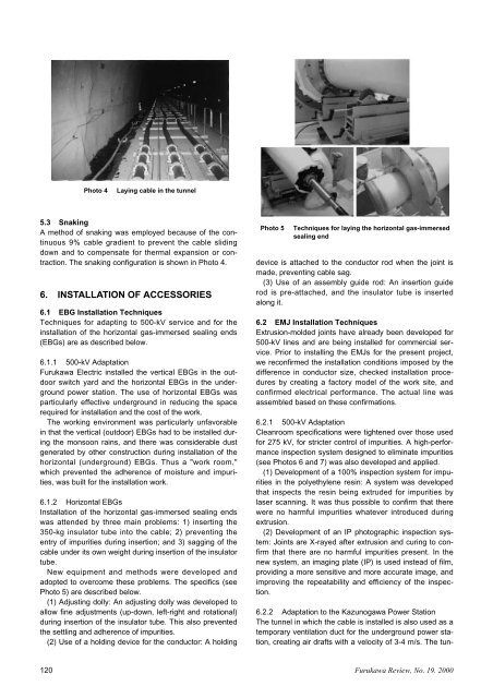
Photo 5 Techniques for laying <strong>the</strong> horizontal gas-immersed<br />
sealing end<br />
device is attached to <strong>the</strong> conductor rod when <strong>the</strong> joint is<br />
made, preventing cable sag.<br />
(3) Use <strong>of</strong> an assembly guide rod: An insertion guide<br />
rod is pre-attached, and <strong>the</strong> insulator tube is inserted<br />
along it.<br />
6.2 EMJ <strong>Installation</strong> Techniques<br />
Extrusion-molded joints have already been developed for<br />
<strong>500</strong>-<strong>kV</strong> lines and are being installed for commercial service.<br />
Prior to installing <strong>the</strong> EMJs for <strong>the</strong> present project,<br />
we reconfirmed <strong>the</strong> installation conditions imposed by <strong>the</strong><br />
difference in conductor size, checked installation procedures<br />
by creating a factory model <strong>of</strong> <strong>the</strong> work site, and<br />
confirmed electrical performance. The actual line was<br />
assembled based on <strong>the</strong>se confirmations.<br />
6.2.1 <strong>500</strong>-<strong>kV</strong> Adaptation<br />
Cleanroom specifications were tightened over those used<br />
for 275 <strong>kV</strong>, for stricter control <strong>of</strong> impurities. A high-performance<br />
inspection system designed to eliminate impurities<br />
(see Photos 6 and 7) was also developed and applied.<br />
(1) Development <strong>of</strong> a 100% inspection system for impurities<br />
in <strong>the</strong> polyethylene resin: A system was developed<br />
that inspects <strong>the</strong> resin being extruded for impurities by<br />
laser scanning. It was thus possible to confirm that <strong>the</strong>re<br />
were no harmful impurities whatever introduced during<br />
extrusion.<br />
(2) Development <strong>of</strong> an IP photographic inspection system:<br />
Joints are X-rayed after extrusion and curing to confirm<br />
that <strong>the</strong>re are no harmful impurities present. In <strong>the</strong><br />
new system, an imaging plate (IP) is used instead <strong>of</strong> film,<br />
providing a more sensitive and more accurate image, and<br />
improving <strong>the</strong> repeatability and efficiency <strong>of</strong> <strong>the</strong> inspection.<br />
6.2.2 Adaptation to <strong>the</strong> Kazunogawa Power Station<br />
The tunnel in which <strong>the</strong> cable is installed is also used as a<br />
temporary ventilation duct for <strong>the</strong> underground power station,<br />
creating air drafts <strong>with</strong> a velocity <strong>of</strong> 3-4 m/s. The tun-<br />
120 Furukawa Review, No. 19. 2000