HSM Shaft Mounted Speed Reducer - Sumitomo Drive Technologies
HSM Shaft Mounted Speed Reducer - Sumitomo Drive Technologies
HSM Shaft Mounted Speed Reducer - Sumitomo Drive Technologies

Create successful ePaper yourself
Turn your PDF publications into a flip-book with our unique Google optimized e-Paper software.
6<br />
How to Select<br />
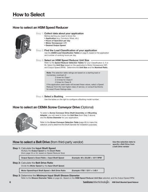
How to select an <strong>HSM</strong> <strong>Speed</strong> <strong>Reducer</strong><br />
Step 1: Collect data about your application<br />
Before starting you need to know the:<br />
• Application (e.g. Conveyor, Mixer, etc.)<br />
• Hours of Operation per day<br />
• Motor Horsepower (HP)<br />
• Desired Output <strong>Speed</strong><br />
Step 2: Find the Load Classification of your application<br />
Use the AGMA Load Classification Tables on page 8, based on the application<br />
and number of working hours per day.<br />
Step 3: Select an <strong>HSM</strong> <strong>Speed</strong> <strong>Reducer</strong> Unit Size<br />
Refer to the <strong>Speed</strong> <strong>Reducer</strong> Selection Tables for your Classification (I, II or<br />
III). Select the Unit Size based on the application’s Motor Horsepower (HP)<br />
and Output <strong>Speed</strong> (RPM). Determine the Unit Size and the Nominal Ratio.<br />
Step 4: Select a Bushing<br />
Use the tables on the right to configure a Bushing model number.<br />
How to select an CEMA Screw Conveyor <strong>Drive</strong> (Optional)<br />
How to select a Belt <strong>Drive</strong> (from third-party vendor)<br />
Step 1: Calculate the Input <strong>Shaft</strong> <strong>Speed</strong><br />
Multiply the Output <strong>Speed</strong> by the Exact Ratio<br />
(from page 53 or 55,<br />
based on <strong>Speed</strong> <strong>Reducer</strong> Size)<br />
Output <strong>Speed</strong> x Exact Ratio = Input <strong>Shaft</strong> <strong>Speed</strong> Example: 48 x 23.235 = 1211 RPM<br />
Step 2: Calculate the Belt <strong>Drive</strong> Ratio<br />
Divide the Motor <strong>Speed</strong> by the Input <strong>Shaft</strong> <strong>Speed</strong>.<br />
Note: The selection table ratings are based on a starting load or<br />
momentary overload of:<br />
2 times for Class I<br />
2-3 times for Class II<br />
4 times for Class III<br />
If the application peak loads will exceed these values, select a <strong>Speed</strong><br />
<strong>Reducer</strong> from the next higher class of service, or consult <strong>Sumitomo</strong><br />
for exact Power Ratings data.<br />
To select a Screw Conveyor <strong>Drive</strong> <strong>Shaft</strong> Assembly and Mounting<br />
Adapter, you will need to know the Unit Size (from Step 3 above)<br />
and the Screw Diameter for your application.<br />
Refer to the Screw Conveyor Selection Table (page 48)<br />
to make this<br />
selection, and to determine the <strong>Shaft</strong> Diameter (for installation purposes).<br />
Motor <strong>Speed</strong>/Input <strong>Shaft</strong> <strong>Speed</strong> = Belt <strong>Drive</strong> Ratio Example:1750 / 1211 = 1.45:1<br />
Use this selection data to<br />
specify a Belt <strong>Drive</strong> from<br />
a belt drive vendor<br />
Step 3: Determine the Minimum Input <strong>Shaft</strong> Sheave Diameter<br />
Refer to the Sheave Diameter Table on page 50. Based on the <strong>HSM</strong> <strong>Speed</strong> <strong>Reducer</strong> Unit Size selected, and the Output <strong>Speed</strong> RPM.