[Complete ELECTRIC scheme] 54 Aprile 2010 ~ Elettronica In
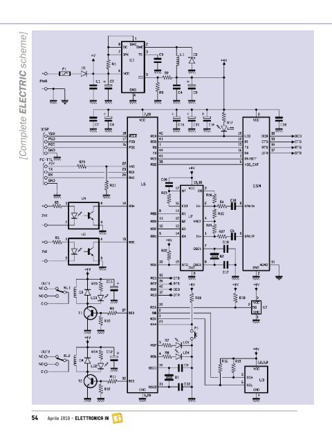
identify the bi-tones involved in the phone selection found within modern telecommunication systems –bi-tones which every phone emits and sends out on phone lines when its keyboard keys are pressed. The identifier is necessary in order for the DTMF functionality to work. Having said that, let’s take a better look at the electric scheme: power is supplied by continuous voltage, not always stabilized (applied to PWR + and -) at a value between 5 and 32 V; such voltage is filtered at the bottom by the diode protecting against polarity inversion (D1) through condensers C1 and C2. Fuse F1 enables us to protect both the circuit and the power source in case of a short circuit in the integrated regulator discussed below, which is necessary to obtain the 4 volts needed for the rest of the circuit to work. The switching regulator is based on a MC34063 chip, utilized in the classic configuration of series PWM regulators charged by inductance, whose output voltage depends on the energy stored in L1; the regulator is stabilized by the component demoted from resistive divider R2/R3, which is needed to set at 4 V the component leveled at the top of both C4 e C5. The 4 volts at the bottom of the abovementioned condensers are sufficiently filtered by other condensers placed on the power lines of the microcontroller and of the <strong>GSM</strong> module; which presents, during transmission, absorption peaks compensated for by C7, C8, C13, C14, C15 e C16, thus avoiding that an impulsive current request may cause the microcontroller to be disturbed. The microcontroller used to handle the whole system is a powerful PIC18F46K20-I/PT by Microchip, which we use in its configuration with an internal clock oscillator; both the scheme and in the printed circuit are nevertheless equipped with external quartz, which we included for those who may want to modify the firmware and develop specific applications requiring an external oscillator. Once the I/O lines have been initialized, the microcontroller verifies the logical state of the opto-isolated inputs at voltage level (RB4 and RB5) as well as that of lines RC4, RC5, RD0, RD3, RX, which are needed to receive the main notifications from the cellular module; more specifically, RD3 is used to detect incoming calls (it interfaces with RI of the cellular module), while RC4 controls the <strong>GSM</strong>’s reception led , whose output (dubbed STATLED) pulsates at a frequency of 1 Hz when the module is searching for the radio-mobile network, and supplies impulses at logical zero, lasting 0.5 seconds and followed by a 2-second pause, when the module has grasped the signal. The frequency and duration of the impulses enable the PIC to understand the conditions of the radio-mobile network range and to behave accordingly; for example, if the opto-isolated input goes off and it needs, therefore, to send SMSs or make calls, but detects that the cellular module has no reception, it waits for the Telit module to get reconnected to the <strong>GSM</strong>/GPRS network before making any calls. The attempt to make calls or send SMSs is repeated only three times, after which the device gives up. The microcontroller contains a UART accessible via pins 44 (transmission) and 1 (reception) which it uses in order to communicate with the cell phone; more precisely, through the first pin (TX), it cyclically questions the module in order to check whether any SMSs have been received, whereas both TX and RX are used to communicate with the <strong>GSM</strong> module when making calls and receiving or sending messages. Regarding the UART, it is important to note that the following control signals are used: CTS (Clear To Send), RTS (Request To Send) and DCD (Data Carrier Detect), which correspond to those of the cellular module being used. They complete the set of I/ Os destined to the cell phone, the RC5 and RD0 lines: the former controls the turning on and off of the <strong>GSM</strong> (though a transistor placed in the small board of the cell phone), while the latter takes care of resetting the cell phone. The button for locally handling this device’s working modality is read through line RA3, configured as input and equipped with an external pull-up resistor (R11) – and therefore active at a low level. Inputs are read through lines RB4 and RB5, both of which are configured as input and equipped with an internal pull-up; each one of them reads the state of the output transistor of the corresponding photocoupler (the optos used here are TLP181). Each of the two available inputs (IN1 and IN2) is active when under a voltage between 3 and 30 V. When a 3-volt voltage (at a minimum) is applied to input IN1, the photocoupler’s LED is switched on and the output phototransitor is in conduction state; therefore, the collector (pin 5) is at about zero volt during I/O configuration, due to the fall on the resistor of the internal pull-up that was configured. If the input is not polarized, the opto-isolator gets inhibited and its pin 4 shows a high level. As for the relays, they are controlled by the microcontroller’s RC0 and RE2 lines, through two NPN transistors driven by current am- Elettronica In ~ Aprile 2010 55