

AN ASSESSMENT OF THE BIT-ERROR-RATE ... - SpaceOps
AN ASSESSMENT OF THE BIT-ERROR-RATE ... - SpaceOps
AN ASSESSMENT OF THE BIT-ERROR-RATE ... - SpaceOps

Create successful ePaper yourself
Turn your PDF publications into a flip-book with our unique Google optimized e-Paper software.
Table 2. Ground Terminal Distortion Settings<br />
Parameter Value<br />
Bandwidth, MHz 650 (3 dB BW)<br />
Roll-off, dB/MHz 6 th order Butterworth roll-off<br />
Gain Flatness<br />
(peak-to-peak), dB<br />
1.2 over ±230 MHz<br />
Gain Slope, dB/MHz 0.1<br />
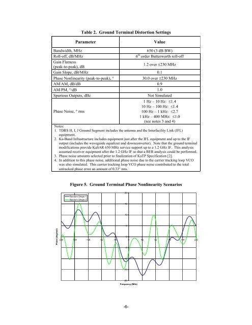
Phase Nonlinearity (peak-to-peak), ° 30.0 over ±230 MHz<br />
AM/AM, dB/dB 0.9<br />
AM/PM, °/dB 1.0<br />
Spurious Outputs, dBc Not Simulated<br />
1 Hz – 10 Hz: ≤1.4<br />
10 Hz – 100 Hz: ≤1.4<br />
Phase Noise, ° rms<br />
100 Hz – 1 kHz: ≤2.7<br />
1 kHz – 400 MHz: ≤1.0<br />
(see notes 3 and 4)<br />
Notes:<br />
1. TDRS H, I, J Ground Segment includes the antenna and the Interfacility Link (IFL)<br />
equipment.<br />
2. Ka-Band Infrastructure includes equipment just after the IFL equipment and up to the IF<br />
output (includes the waveguide equalizer and downconverter). Note that the ground terminal<br />
modifications provide KaSAR 650 MHz service support up to a 1.2 GHz IF. This analysis<br />
assumed receiver equipment after the 1.2 GHz IF so that a BER analysis could be performed.<br />
3. Phase noise amounts selected prior to finalization of KaTP Specification [2].<br />
4. In addition to this phase noise, additional phase noise due to the carrier tracking loop VCO<br />
was also simulated. This carrier tracking loop VCO phase noise contributed to the total<br />
untracked phase error an amount of 0.33° rms.<br />
Phase (degrees)<br />
Figure 5. Ground Terminal Phase Nonlinearity Scenarios<br />
Random Shape 1<br />
Random Shape 2<br />
20<br />
15<br />
10<br />
5<br />
0<br />
-230 -184 -138 -92 -46 0 46 92 138 184 230<br />
-5<br />
-10<br />
-15<br />
-20<br />
Frequency (MHz)<br />
-6-