Technical Handbook - Gasket Fabricators Association
Technical Handbook - Gasket Fabricators Association
Technical Handbook - Gasket Fabricators Association

Create successful ePaper yourself
Turn your PDF publications into a flip-book with our unique Google optimized e-Paper software.
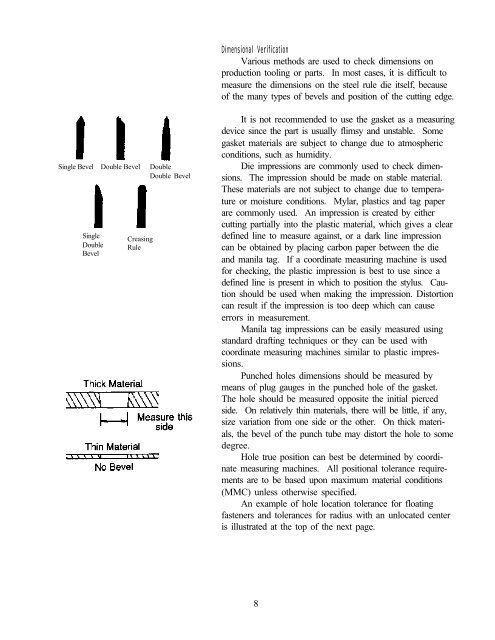
Single Bevel Double Bevel Double<br />
Double Bevel<br />
Single<br />
Double<br />
Bevel<br />
Creasing<br />
Rule<br />
Dimensional Verification<br />
Various methods are used to check dimensions on<br />
production tooling or parts. In most cases, it is difficult to<br />
measure the dimensions on the steel rule die itself, because<br />
of the many types of bevels and position of the cutting edge.<br />
It is not recommended to use the gasket as a measuring<br />
device since the part is usually flimsy and unstable. Some<br />
gasket materials are subject to change due to atmospheric<br />
conditions, such as humidity.<br />
Die impressions are commonly used to check dimensions.<br />
The impression should be made on stable material.<br />
These materials are not subject to change due to temperature<br />
or moisture conditions. Mylar, plastics and tag paper<br />
are commonly used. An impression is created by either<br />
cutting partially into the plastic material, which gives a clear<br />
defined line to measure against, or a dark line impression<br />
can be obtained by placing carbon paper between the die<br />
and manila tag. If a coordinate measuring machine is used<br />
for checking, the plastic impression is best to use since a<br />
defined line is present in which to position the stylus. Caution<br />
should be used when making the impression. Distortion<br />
can result if the impression is too deep which can cause<br />
errors in measurement.<br />
Manila tag impressions can be easily measured using<br />
standard drafting techniques or they can be used with<br />
coordinate measuring machines similar to plastic impressions.<br />
Punched holes dimensions should be measured by<br />
means of plug gauges in the punched hole of the gasket.<br />
The hole should be measured opposite the initial pierced<br />
side. On relatively thin materials, there will be little, if any,<br />
size variation from one side or the other. On thick materials,<br />
the bevel of the punch tube may distort the hole to some<br />
degree.<br />
Hole true position can best be determined by coordinate<br />
measuring machines. All positional tolerance requirements<br />
are to be based upon maximum material conditions<br />
(MMC) unless otherwise specified.<br />
An example of hole location tolerance for floating<br />
fasteners and tolerances for radius with an unlocated center<br />
is illustrated at the top of the next page.<br />
8