Differential Rebuild Instructions - The Corvette Restoration Page
Differential Rebuild Instructions - The Corvette Restoration Page
Differential Rebuild Instructions - The Corvette Restoration Page

You also want an ePaper? Increase the reach of your titles
YUMPU automatically turns print PDFs into web optimized ePapers that Google loves.
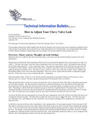
Installation Kit <strong>Instructions</strong><br />
Please read completely<br />
before beginning.<br />
Over the years we have gathered information from Gleason gear design<br />
manuals, Dana Spicer instruction manuals and technical bulletins, and<br />
General Motors repair manuals. We have personally experienced good results<br />
using the techniques in these instructions when setting up over thirty<br />
thousand differentials.<br />
We highly recommend Timken bearings and have used them for as long as<br />
we can remember. We believe Timken bearings have held up best in all of the<br />
differentials we have assembled and disassembled. We also recommend<br />
using only new or good used parts. New parts are usually worth installing<br />
and save a lot of time and money that can be lost by using worn or<br />
questionable parts that lead to early failure.<br />
Ring & pinion gears are designed to be set-up and run with exact<br />
tolerances. Replacing all parts every time a differential is worked on is not<br />
only unnecessary but is ridiculous. However any gear misalignment or<br />
deflection under load caused by worn or questionable parts can lead to early<br />
failure that can cost a lot more than the price of replacing them the first time.<br />
Use your best judgment and remember that fixing your differential again if it<br />
fails will take as much time and money as it did the first time.<br />
We hope that these instructions are helpful and you are able to get years of<br />
use from your differential.<br />
Thank you Robert Hunt, Jeff Wilson, and Gregg Lloyd for your expert input<br />
and advice.<br />
© Copyright 1993-2001/Yukon Gear & Axle<br />
Installation Kit <strong>Instructions</strong> 1
When working on your differential you will need a wide variety of tools. It is always<br />
recommended that you use the right tools for the job. Using the correct tools will save<br />
you time and help prevent parts from being damaged. Here is a list of some of the tools<br />
that you may need:<br />
• Dial indicator<br />
• Genuine gear marking compound and a clean brush<br />
• Calipers or a micrometer<br />
• Bearing pullers<br />
• Bearing press<br />
• Misc. hand and air tools including:<br />
• Three foot long breaker bar or strong impact gun<br />
• Pinion nut socket<br />
• Ring gear bolt socket<br />
• Main cap bolt socket<br />
• Six point cross pin bolt wrench<br />
• Brake line wrench<br />
• Pry bars for removing the carrier case<br />
• 24 oz ball peen hammer<br />
• 48 oz sledge hammer<br />
• 48 oz plastic dead blow hammer<br />
• Assorted brass punches<br />
• Center punch or number stamp for marking main caps<br />
• Oil drain pan<br />
• Torque wrenches:<br />
• foot pounds<br />
• inch pounds<br />
2 Installation Kit <strong>Instructions</strong><br />
Tool List
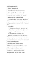
1. Before I start working on anything I always make certain that I have everything I need<br />
before I start. Check all of your new parts to be sure that you have everything you<br />
need and make certain that you have received all of the parts that you ordered.<br />
2. <strong>The</strong> next step is to lift the vehicle using an appropriate lift or a jack and safe jack<br />
stands. Always make certain that the vehicle is safe to be under before starting to<br />
work on the vehicle.<br />
3. <strong>The</strong>n drain the oil into a suitable container. We always recycle our waste oil and hope<br />
that you will be able to recycle yours too.<br />
4. Next remove the axles shafts.<br />
5. Mark both of the main caps so that you will be able to re-install them on the same side<br />
in the same direction as they came off.<br />
6. Keep track of the position of all of the original shims.<br />
7. Clean and inspect all parts.<br />
Disassembly<br />
Installation Kit <strong>Instructions</strong> 3
Assembly Oil<br />
When assembling I use a moderate coat<br />
of gear oil on all of the bearings and<br />
grease or oil on all of the seals and seal<br />
surfaces. I do not use bearing grease on<br />
any pinion or carrier bearings, only clean<br />
gear oil.<br />
4 Installation Kit <strong>Instructions</strong><br />
Assembly<br />
Order of Adjustments<br />
When assembling or setting up a differential there are four basic adjustments. In the order<br />
of importance they are:<br />
1. Pinion Depth<br />
2. Pinion Bearing Preload<br />
3. Backlash<br />
4. Carrier Bearing Preload<br />
Selecting Shims<br />
For my first assembly I usually start with the shims that were used in the differential<br />
during the previous assembly. If the original shims from the previous assembly are not<br />
available then I recommend using the thickness listed in the specifications information.<br />
Preparing Parts<br />
Before assembly I clean all parts, including the new ones, with clean solvent. I wash out<br />
the housing with solvent and check all of the oil passages to make certain that there are<br />
no metal particles or dirt that can lead to early wear. On many housings there are oil<br />
passages to the pinion and grooves just outside of the carrier bearings where metal<br />
particles hide. Be sure to check all passages and groves for metal particles and dirt!<br />
Seal Preparation<br />
All seal surfaces can be polished with light emery cloth or sandpaper and then wiped<br />
with a clean rag and clean oil or solvent to remove the metal particles left after sanding.
Pinion Trial Assembly<br />
I have found it is easiest to assemble the pinion without a crush sleeve until the<br />
correct pinion depth has been established. When initially installing the pinion I slowly<br />
tighten the pinion nut until the preload is within the assembly specifications.<br />
Initial Carrier Assembly<br />
I have also found it works well to assemble the carrier snug but not tight during trial<br />
assemblies so it is easier to remove and replace during the several attempts necessary to<br />
find the shim combination for correct pinion depth and backlash.<br />
After installing the pinion, the first<br />
adjustment I make is backlash. I believe a<br />
clear indication of pinion depth can only<br />
be obtained when the backlash is within,<br />
or very close to specifications. I have<br />
found the backlash will change about<br />
0.007” for each 0.010” that the carrier is<br />
moved. If I want to decrease the backlash<br />
by 0.007” I move the carrier 0.010” closer<br />
to the pinion. If I want to increase the<br />
backlash by 0.007” I move the ring gear<br />
0.010” farther away from the pinion. This<br />
is not exact for all ring & pinion sets, but<br />
it is a good general guideline.<br />
Adjusting Backlash<br />
Checking the Pattern<br />
After setting the backlash the next setting to check is the pinion depth. When<br />
checking the pinion depth I use only genuine gear marking compound. Gear marking<br />
compound gives a clear indication of gear contact without running or smearing. I<br />
usually mix a little oil with the marking compound so that it is smooth but not runny. I<br />
brush three or four of the ring gear teeth with a moderate coat of compound in two<br />
different places on the ring gear. <strong>The</strong>n I rotate the ring gear past the pinion gear four or<br />
five times to obtain a good pattern.<br />
Important Pattern Information!<br />
Reading the contact pattern is easy as long as I am not mislead or sidetracked. <strong>The</strong><br />
only part of the pattern that helps me set the pinion depth correctly is the contact<br />
position with regards to the face and flank of the teeth. If the contact pattern appears to<br />
be towards the heel or the toe of the ring gear teeth I pay no attention and look only at<br />
the pattern position from face to flank. <strong>The</strong> pattern will also change from heel to toe<br />
but in most cases an ideal heel to toe pattern can not be achieved. Trying to obtain a<br />
Installation Kit <strong>Instructions</strong> 5
pattern that is centered from heel to toe will usually lead to frustration and a noisy gear<br />
set. Even if it does not seem intuitive or reasonable, I am only concerned with the<br />
position of the pattern from face to flank. I have found that housing alignment and the<br />
position of the pinion bearing bore in the housing affects the pattern from heel to toe and<br />
can not be corrected without machine work. A contact pattern that is centered from face<br />
to flank always indicates correct pinion depth even if a pattern that is centered from heel<br />
to toe can not be obtained.<br />
Ideal pattern<br />
If the contact pattern is towards the face<br />
of the ring gear teeth then the pinion is too<br />
far away from the ring gear. To correct the<br />
pattern the pinion needs to be moved<br />
towards the ring gear so that it is positioned<br />
closer to the ring gear centerline.<br />
If the contact pattern is towards the flank<br />
of the ring gear teeth then the pinion is too<br />
close to the ring gear. To correct the pattern<br />
the pinion needs to be moved away from the<br />
ring gear so that it is positioned farther<br />
away from the ring gear centerline.<br />
Used Gear Sets<br />
When setting up a used ring & pinion I am<br />
basically concerned with the pattern on the coast<br />
side of the ring gear teeth and I pay very little<br />
attention to the drive side of the gear teeth. This<br />
is true for most used gear sets but in some cases<br />
both the coast and drive side should be<br />
considered.<br />
Adjusting Pinion Depth<br />
When changing the pinion depth I always make<br />
large changes until the pattern is close. I<br />
consider 0.005” to 0.015” to be a large change<br />
and 0.002” to 0.004” to be a small change.<br />
Changes of 0.005” to 0.008” or more will lead to<br />
the correct pattern faster than small changes<br />
will. I purposely make adjustments that I know Used drive pattern<br />
are moving the pinion too far. If I move the pinion too far and the pattern changes from<br />
one extreme to the other then I know that the correct pattern is somewhere between<br />
the two extremes. Once I get close to the correct pinion depth I make smaller changes<br />
until the pattern is centered between the face and the flank of the ring gear teeth.<br />
After the backlash and pinion depth are set I remove the carrier and set the final pinion<br />
bearing preload.<br />
6 Installation Kit <strong>Instructions</strong><br />
Assembly<br />
(continued)
Setting Pinion Bearing Preload<br />
In differentials that use a crush sleeve this is relatively easy. I always use a new crush<br />
sleeve for final assembly. I use oil on the pinion nut washer surface during all assemblies<br />
and red Loctite on the pinion nut threads during the final assembly. <strong>The</strong> oil on the<br />
washer surface helps the nut turn easier while it is being tightened and the red Loctite<br />
helps keep it tight.<br />
Crush Sleeve Design<br />
On a crush sleeve design differential it usually takes between three hundred (300)<br />
and four hundred (400) foot pounds of torque to crush the crush sleeve. Over the years<br />
I have used huge breaker bars and or very strong air operated impact wrenches to<br />
crush the crush sleeve. I also proceed very slowly so that I get it right the first time.<br />
<strong>The</strong> pinion preload will be zero until the bearings contact the races. When the bearings<br />
contact the races the preload will increase very quickly. Again, I recommend taking<br />
plenty of time to set the preload carefully so that the bearings will have a long life. If<br />
the crush sleeve is over crushed and the pinion bearing preload exceeds the specified<br />
allowable range the only solution that I know of is to install another new crush sleeve<br />
and start over. After reaching the correct preload I moderately tap both ends of the<br />
pinion to seat the bearings, races and yoke. Be careful not to hit the pinion so hard that<br />
it damages the bearings. After “seating” the pinion I check the preload again to make<br />
certain that it is correct.<br />
Preload Shim Design<br />
If the differential uses shims to set the pinion bearing preload then this step may take a<br />
few times to get it right. I usually use the original shims on the first assembly or add<br />
0.003” to the original preload shims to make up for the bearings settling into the housing.<br />
When first tightening the pinion nut I am careful to tighten it slowly so as not to damage<br />
the bearing if the preload shim stack is not thick enough.<br />
If the preload is too loose then I<br />
remove shims so that the bearings<br />
will be tighter against the races<br />
and increase the preload.<br />
If the preload is too tight then I<br />
add shims so that the bearings will<br />
not be as tight against the races.<br />
I am always very careful to clean<br />
the shims completely so that there<br />
are no particles that may cause a<br />
false preload reading or cause the<br />
shim stack to change thickness<br />
over time as the vehicle is driven.<br />
Impact on pinion nut<br />
Installation Kit <strong>Instructions</strong> 7
8 Installation Kit <strong>Instructions</strong><br />
Assembly<br />
(continued)<br />
When making preload shim changes I like to remember where I started and which<br />
thickness’ I have tried. I recommend writing down the thickness and resulting preload of<br />
each shim combination tried.<br />
After reaching the correct preload I moderately tap both ends of the pinion to seat the<br />
bearings, races and yoke. Be careful not to hit the pinion so hard that it damages the<br />
bearings. After “seating” the pinion I check the preload again to make certain it is correct.<br />
After setting the pinion depth, backlash, and pinion bearing preload I set the carrier<br />
bearing preload. I like to set the carrier bearing preload fairly tight. <strong>The</strong>re are three<br />
different shim or adjustment methods that cover most differentials.<br />
Final Backlash & Carrier Bearing<br />
Preload Adjustments<br />
Screw Adjuster Design<br />
<strong>The</strong> first and easiest method uses screw adjusters to set the backlash and carrier<br />
bearing preload. When setting the carrier bearing preload on this type of differential I<br />
am careful to oil the adjuster threads on both the housing and on the adjusters<br />
themselves. I am also careful about the order in which I tighten the adjusters so that the<br />
backlash stays where it should even when under heavy loads.<br />
<strong>The</strong> ring gear is always forced away from the pinion gear when ever it is transferring<br />
power and it is never forced toward the pinion gear. When setting the backlash and<br />
carrier bearing preload on a differential that uses screw adjusters I start with the<br />
backlash wider than the final setting that I am adjusting it to. I always make certain the<br />
last adjustment that I make on the left adjuster is to tighten it. If the backlash becomes<br />
too tight I start over by opening it to a position where it is too wide again by backing off<br />
pressure from the left adjuster and then I use the right adjuster to open up the backlash<br />
again. At this point I tighten the left adjuster which closes down the backlash toward the<br />
final setting. I always make certain that the last adjustment that I make on the left<br />
adjuster is to tighten it so that there is no possibility of a space between the adjuster and<br />
the bearing race. Any space or looseness on the left side can let the carrier move when<br />
under load and this can cause the backlash to open up.<br />
After the backlash approaches the final setting I tighten both the left and right<br />
adjusters evenly so that the carrier bearing preload increases. I like to set the carrier<br />
bearing preload as tight as I can with a ten (10) or twelve (12) inch long spanner wrench.<br />
I have never encountered carrier bearing failure due to excessive carrier bearing preload<br />
on a screw adjuster type differential.<br />
If the preload is close and the backlash is too wide I tighten the left adjuster a notch or<br />
two until the backlash is correct and the preload is tight.<br />
If the preload is close and the backlash is too tight I tighten the right adjuster until the<br />
backlash is correct and the preload is tight.<br />
Like I stated before, I always make certain that the last adjustment that I make on the left
adjuster is to tighten it so that there is no possibility of a space between the adjuster and the<br />
bearing race.<br />
Outside Shim Design<br />
<strong>The</strong>re are also designs that use shims between the carrier bearing races and the<br />
housing. On these types of differentials I set the carrier bearing preload as tight as I can<br />
without damaging the shims while driving them in. I have seldom seen carrier bearings<br />
fail in this rearend design because of excessive carrier bearing preload. During the<br />
original set-up of this design I set the<br />
backlash with very little carrier bearing<br />
preload. After I have set the backlash I add<br />
shims to both the left and the right sides until<br />
I obtain the correct preload.<br />
Inside Shim Design<br />
If the preload is close and the backlash is<br />
wide I add shims to the left side. This<br />
increases the carrier bearing preload and<br />
tightens the backlash at the same time.<br />
If the preload is close and the backlash is<br />
too tight I add shims to the right side. This<br />
increases both the carrier bearing preload and<br />
the backlash at the same time.<br />
<strong>The</strong> last design uses shims between the carrier bearing and the carrier case. On this<br />
design I also set the preload very tight but not so tight that the carrier is difficult to install<br />
or remove. I keep the preload very light while setting the backlash so that the carrier is<br />
easy to remove and install. After I have set the backlash I add shims to both the left and<br />
right sides evenly until I obtain the correct preload.<br />
Pressing on carrier bearing<br />
If the preload is close and the backlash is wide I add<br />
shims to the left side. This increases the carrier bearing<br />
preload and tightens Carrier bearing puller<br />
the backlash at the<br />
same time.<br />
If the preload is<br />
close and the<br />
backlash is too tight I<br />
add shims to the right<br />
side. This increases<br />
the carrier bearing<br />
preload and the<br />
backlash at the same<br />
time.
Pattern<br />
Now that the pinion depth, pinion bearing preload, backlash, and carrier bearing<br />
preload are set I recheck the pattern once more to be certain that everything is perfect.<br />
Oil<br />
When filling the differential I use high quality name brand gear oil and make certain<br />
that I fill the unit completely.<br />
Break-In<br />
All new gear sets require a break-in period to prevent damage from overheating. After<br />
driving the first 15 or 20 miles it is best to let the differential cool before proceeding. I<br />
recommend at least 500 miles before towing. I also recommend towing for very short<br />
distances (less than 15 miles) and letting the differential cool before continuing during<br />
the first 45 towing miles. This may seem unnecessary but I have seen many differentials<br />
damaged from being loaded before the gear set was broken-in. I also recommend<br />
changing the gear oil after the first 500 miles. This will remove any metal particles or<br />
phosphorus coating that has come from the new gear set.<br />
ANY OVERLOADING OR OVERHEATING<br />
WILL CAUSE THE GEAR OIL TO BREAK DOWN<br />
AND THE RING & PINION WILL FAIL.<br />
I hope that these instructions have been helpful and you get years of good service<br />
from your differential<br />
Burned ring & pinion<br />
10 Installation Kit <strong>Instructions</strong><br />
Final Checks
Heel<br />
(Outer end)<br />
Tooth Nomenclature<br />
Terms for describing specific areas<br />
of the gear teeth<br />
End view of tooth from Heel<br />
(Outer end)<br />
Coast<br />
Drive<br />
(Convex)<br />
Face (Top Land)<br />
Flank (Root)<br />
Drive<br />
Coast<br />
(Concave)<br />
Toe<br />
(Inner end)<br />
Installation Kit <strong>Instructions</strong> 11
Heel<br />
(Outer end)<br />
Heel<br />
(Outer end)<br />
Heel<br />
(Outer end)<br />
Drive<br />
Drive<br />
Drive<br />
12 Installation Kit <strong>Instructions</strong><br />
Acceptable Patterns<br />
Coast<br />
Coast<br />
Coast<br />
Toe<br />
(Inner end)<br />
Toe<br />
(Inner end)<br />
Toe<br />
(Inner end)<br />
Heel<br />
(Outer end)<br />
Heel<br />
(Outer end)<br />
Heel<br />
(Outer end)<br />
Drive<br />
Drive<br />
Drive<br />
Coast<br />
Coast<br />
Coast<br />
Toe<br />
(Inner end)<br />
Toe<br />
(Inner end)<br />
Toe<br />
(Inner end)
Heel<br />
(Outer end)<br />
Heel<br />
(Outer end)<br />
Heel<br />
(Outer end)<br />
Drive<br />
Drive<br />
Drive<br />
Pinion is Too Close<br />
Coast<br />
Coast<br />
Coast<br />
Toe<br />
(Inner end)<br />
Toe<br />
(Inner end)<br />
Toe<br />
(Inner end)<br />
Heel<br />
(Outer end)<br />
Heel<br />
(Outer end)<br />
Heel<br />
(Outer end)<br />
Drive<br />
Drive<br />
Drive<br />
Coast<br />
Coast<br />
Coast<br />
Toe<br />
(Inner end)<br />
Toe<br />
(Inner end)<br />
Toe<br />
(Inner end)<br />
Installation Kit <strong>Instructions</strong> 13
Heel<br />
(Outer end)<br />
Heel<br />
(Outer end)<br />
Heel<br />
(Outer end)<br />
Drive<br />
Drive<br />
Drive<br />
14 Installation Kit <strong>Instructions</strong><br />
Pinion is Too Far Away<br />
Coast<br />
Coast<br />
Coast<br />
Toe<br />
(Inner end)<br />
Toe<br />
(Inner end)<br />
Toe<br />
(Inner end)<br />
Heel<br />
(Outer end)<br />
Heel<br />
(Outer end)<br />
Heel<br />
(Outer end)<br />
Drive<br />
Drive<br />
Drive<br />
Coast<br />
Coast<br />
Coast<br />
Toe<br />
(Inner end)<br />
Toe<br />
(Inner end)<br />
Toe<br />
(Inner end)
SUMMARY OF INSTRUCTIONS<br />
All sets are matched pairs. Make sure you have a matched set. Clean all parts before<br />
you start assembly. Apply a light coat of oil to all bearings. Examine all components and<br />
remove any burs, nicks or sharp edges that could cause components not to seat properly.<br />
Checking Backlash<br />
1. Set backlash to proper clearance. (See specification sheet)<br />
2. Backlash is the free movement of the ring gear with the pinion help fixed in place.<br />
3. Correct backlash is obtained by shimming or adjusting the<br />
ring gear away from or closer to the pinion.<br />
4. Pinion bearing preload should be as specified on specification<br />
sheet. This is accomplished by a preload shim pack (of various<br />
thicknesses) or a collapsible crush sleeve. A new crush sleeve<br />
should always be used during final assembly.<br />
5. Correct pinion depth is obtained by shimming the pinion in or<br />
out, to obtain the correct tooth pattern. All housing are not<br />
shimmed in the same location, but shimming still moves the<br />
pinion closer to, or farther away from the ring gear. It is suggested<br />
that you start with the same shim thickness on the new<br />
gear set as was used on the old set.<br />
OBTAINING PROPER GEAR PATTERN (Pinion Depth)<br />
Drive Side Coast Side<br />
Heel Toe Toe Heel<br />
• Normal or desirable pattern. <strong>The</strong> pattern should be<br />
centered on the tooth from face to flank. <strong>The</strong>re should<br />
usually be some clearance between the pattern and the<br />
top of the tooth (face), and always between the pattern<br />
and the bottom of the tooth (flank).<br />
• Pinion is too close. Move the pinion away from the<br />
ring gear centerline.<br />
• Pinion is too far away. Move the pinion towards the<br />
ring gear centerline.<br />
PATTERN MOVEMENTS SUMMARIZED<br />
1. Moving the ring gear closer to the pinion will decrease backlash.<br />
2. Moving the ring gear farther away from the ring gear will increase backlash.<br />
3. Moving the pinion closer to the ring gear will move the drive pattern deeper on the<br />
tooth (flank contact) and slightly toward the toe. <strong>The</strong> coast pattern will move deeper<br />
on the tooth and slightly toward the heel.<br />
4. Moving the pinion further away from the ring gear will move the drive pattern toward<br />
the top of the tooth (face) and slightly toward the heel. <strong>The</strong> coast pattern will move<br />
toward the top of the tooth and toward the toe.<br />
Installation Kit <strong>Instructions</strong> 15
AMC<br />
Model 20 . . . . . . . . . . . . . . . .14-19 . . . . . .6-8 . . . . .6-10 . . . . . . .65 . . . . . . .65<br />
Model 35 . . . . . . . . . . . . . . . .12-15 . . . . . .6-7 . . . . .6-10 . . . . . . .55 . . . . . . .55<br />
GENERAL MOTORS<br />
Olds/Pont D/O . . . . . . . . . . . .14-19 . . . . . .6-7 . . . . .6-10 . . . . . . .55 . . . . . . .70<br />
’63-’79 <strong>Corvette</strong> . . . . . . . . . . .14-19 . . . . . .6-8 . . . . .6-10 . . . . . . .55 . . . . . . .60<br />
D36 <strong>Corvette</strong> . . . . . . . . . . . . .12-15 . . . . . .6-8 . . . . .6-10 . . . . . . .55 . . . . . . .55<br />
D44 <strong>Corvette</strong> . . . . . . . . . . . . .14-19 . . . . . .6-9 . . . . .6-10 . . . . . . .55 . . . . . . .55<br />
55P & 55T . . . . . . . . . . . . . . .14-18 . . . . . .6-8 . . . . .6-10 . . . . . . .55 . . . . . . .60<br />
7.2” . . . . . . . . . . . . . . . . . . . .11-14 . . . . . .6-7 . . . . .6-10 . . . . . . .55 . . . . . . .60<br />
7.5” . . . . . . . . . . . . . . . . . . . .12-15 . . . . . .6-7 . . . . .6-10 . . . . . . .65 . . . . . . .60<br />
7.75” . . . . . . . . . . . . . . . . . . .12-15 . . . . . .6-7 . . . . .6-10 . . . . . . .65 . . . . . . .60<br />
8.2” . . . . . . . . . . . . . . . . . . . .12-15 . . . . . .6-7 . . . . .6-10 . . . . . . .55 . . . . . . .60<br />
8.2” Olds/Pont . . . . . . . . . . . .12-15 . . . . . .6-7 . . . . .6-10 . . . . . . .55 . . . . . . .60<br />
8.25” IFS . . . . . . . . . . . . . . . .14-19 . . . . . .6-8 . . . . .6-10 . . . . . . .65 . . . . . . .55<br />
8.5” & 8.6” . . . . . . . . . . . . . . .14-19 . . . . . .6-8 . . . . .6-10 . . . . . . .65 . . . . . . .60<br />
9.25” IFS . . . . . . . . . . . . . . . .15-22 . . . . . .7-9 . . . . .6-10 . . . . . . .75 . . . . . . .80<br />
9.5” . . . . . . . . . . . . . . . . . . . .15-22 . . . . . .7-9 . . . . .6-10 . . . . . . .75 . . . . . . .80<br />
12 Bolt Pass . . . . . . . . . . . . . .14-19 . . . . . .6-8 . . . . .6-10 . . . . . . .55 . . . . . . .60<br />
12 Bolt Truck . . . . . . . . . . . . .13-15 . . . . . .6-7 . . . . .6-10 . . . . . . .55 . . . . . . .60<br />
14T 10-1/2” . . . . . . . . . . . . . .20-35 . . . . .8-11 . . . . .6-10 . . . . . .120 . . . . . .135<br />
HO72 (10” R/G) . . . . . . . . . PRESET . . . . . . . . . . . . . .6-10 . . . . . .120 . . . . . .175<br />
CHRYSLER<br />
7-1/4” . . . . . . . . . . . . . . . . . .12-14 . . . . . .6-7 . . . . .6-10 . . . . . . .55 . . . . . . .50<br />
8-1/4” . . . . . . . . . . . . . . . . . .12-15 . . . . . .6-8 . . . . .6-10 . . . . . . .55 . . . . . . .60<br />
8-3/4” ’41’ . . . . . . . . . . . . . . .13-15 . . . . . .6-8 . . . . .6-10 . . . . . . .55 . . . . . . .90<br />
8-3/4” ’42’ . . . . . . . . . . . . . . .15-25 . . . . .7-10 . . . . .6-10 . . . . . . .55 . . . . . . .90<br />
8-3/4” ’89’ . . . . . . . . . . . . . . .14-19 . . . . . .6-9 . . . . .6-10 . . . . . . .55 . . . . . . .90<br />
9-1/4” . . . . . . . . . . . . . . . . . .14-19 . . . . . .6-9 . . . . .6-10 . . . . . . .65 . . . . . . .75<br />
DANA<br />
D25 . . . . . . . . . . . . . . . . . . . .12-15 . . . . . .6-7 . . . . .6-10 . . . . . . .55 . . . . . . .50<br />
D27 . . . . . . . . . . . . . . . . . . . .12-15 . . . . . .6-7 . . . . .6-10 . . . . . . .55 . . . . . . .50<br />
D28 . . . . . . . . . . . . . . . . . . . .10-13 . . . . . .5-6 . . . . .6-10 . . . . . . .55 . . . . . . .50<br />
D30 . . . . . . . . . . . . . . . . . . . .12-15 . . . . . .6-8 . . . . .6-10 . . . . . . .55 . . . . . . .60<br />
D44 . . . . . . . . . . . . . . . . . . . .14-19 . . . . . .6-9 . . . . .6-10 . . . . . . .55 . . . . . . .60<br />
D50 . . . . . . . . . . . . . . . . . . . .14-19 . . . . . .6-9 . . . . .6-10 . . . . . . .65 . . . . . . .60<br />
D60, 61 & 70U . . . . . . . . . . .17-30 . . . . .8-10 . . . . .6-10 . . . . . .110 . . . . . . .80<br />
D70 & 70HD . . . . . . . . . . . . .20-35 . . . . .8-10 . . . . .6-10 . . . . . .110 . . . . . . .80<br />
D80 . . . . . . . . . . . . . . . . . . . .25-40 . . . . .9-11 . . . . .4-10 . . . . . .175 . . . . . . .90<br />
FORD<br />
7.5” . . . . . . . . . . . . . . . . . . . .14-19 . . . . . .6-8 . . . .11-16 . . . . . . .60 . . . . . . .60<br />
8.0” . . . . . . . . . . . . . . . . . . . .12-14 . . . . . .6-7 . . . .10-15 . . . . . . .60 . . . . . . .60<br />
8.7” . . . . . . . . . . . . . . . . . . . .14-19 . . . . . .6-8 . . . .10-15 . . . . . . .60 . . . . . . .60<br />
8.8” . . . . . . . . . . . . . . . . . . . .14-19 . . . . . .6-8 . . . .11-16 . . . . . . .60 . . . . . . .60<br />
9.0” OEM R&P . . . . . . . . . . . .13-15 . . . . . .6-7 . . . .10-16 . . . . . . .60 . . . . . . .60<br />
9.0” NON OEM . . . . . . . . . . . . . . . . . . . . . . . . . . . . . . .7-10<br />
9.0” Daytona . . . . . . . . . . . . .14-16 . . . . . .6-8<br />
9-3/8” . . . . . . . . . . . . . . . . . .14-16 . . . . . .6-8 . . . .10-15 . . . . . . .70 . . . . . . .60<br />
9-3/4” . . . . . . . . . . . . . . . . . .15-19 . . . . . .6-8 . . . .10-15 . . . . . . .75 . . . . . . .70<br />
10- 1/4” & 10-1/2” . . . . . . . .20-35 . . . . . .6-8 . . . .11-16 . . . . . . .95 . . . . . . .80<br />
TOYOTA<br />
Passenger . . . . . . . . . . . . . . .11-13 . . . . . .5-6 . . . . . .6-9 . . . . . . .55 . . . . . . .60<br />
7.5” F. or R. . . . . . . . . . . . . . .12-15 . . . . . .5-6 . . . . .6-10 . . . . . . .70 . . . . . . .70<br />
8” F. or R. . . . . . . . . . . . . . . . .12-15 . . . . . .5-6 . . . . .6-10 . . . . . . .70 . . . . . . .70<br />
Truck V6 R. . . . . . . . . . . . . . .14-17 . . . . . .5-6 . . . . .6-10 . . . . . . .70 . . . . . . .70<br />
T100 & Tacoma . . . . . . . . . . .14-17 . . . . . .5-6 . . . . .6-10 . . . . . . .70 . . . . . . .70<br />
16 Installation Kit <strong>Instructions</strong><br />
© Copyright 1993-2001/Yukon Gear & Axle<br />
PINION BEARING<br />
DIFF PRELOAD R.G. BOLT CAP<br />
MODEL NEW USED B/L TORQUE TORQUE<br />
(inch lbs) (0.000”) (Foot lbs)<br />
PINION BEARING<br />
DIFF PRELOAD R.G. BOLT CAP<br />
MODEL NEW USED B/L TORQUE TORQUE<br />
(inch lbs) (0.000”) (Foot lbs)<br />
Set Up Specifications