Katalog Catalog - 2E mechatronic
Katalog Catalog - 2E mechatronic
Katalog Catalog - 2E mechatronic

You also want an ePaper? Increase the reach of your titles
YUMPU automatically turns print PDFs into web optimized ePapers that Google loves.
<strong>Katalog</strong><br />
Steckverbinder<br />
<strong>Catalog</strong><br />
Connectors
Allgemeine Geschäftsbedingungen finden Sie<br />
auf www.2e-<strong>mechatronic</strong>.de<br />
3<br />
11<br />
13<br />
15<br />
17<br />
19<br />
20<br />
26<br />
29<br />
31<br />
32<br />
35<br />
36<br />
37<br />
3<br />
11<br />
13<br />
15<br />
17<br />
19<br />
20<br />
26<br />
29<br />
31<br />
32<br />
35<br />
36<br />
37<br />
General terms and conditions are available<br />
at www.2e-<strong>mechatronic</strong>.de
GLOSSAR<br />
Ader<br />
Elektris ch leitendes Material, oft mit einer<br />
Isolierung geschützt. Kabel können eine<br />
oder mehrere Adern haben.<br />
Anschlussbereich<br />
Bereich des Kontaktes, mit dem ein Leiter,<br />
z. B. ein Kabel, oder eine Leiterplatte elektrisch<br />
leitend verbunden wird.<br />
Anschlussstück<br />
Teil eines Bauelementes, das erneute Verbindungen<br />
ermöglicht.<br />
Anschlusstechniken<br />
Methoden zum Anschließen von Leitungen<br />
an die Kontakte. Es gibt lötfreie Verfahren,<br />
wie z. B. Crimp-, Wickel-, Schneidklemm-,<br />
Federklemm-, Klammer-, Schraub- und Einpresstechnik.<br />
Lötverbindungen sind z. B.<br />
Schwalllöten (Wellenlöten), Handlöten<br />
(Löt kolben), Reflowlöten, Dampfphasenlöten.<br />
Bauart<br />
Steckverbinderart, z. B. Steckverbinder<br />
nach IEC 60603-2 (früher DIN 41612).<br />
Bauform<br />
Eine Bauform ist ein einzelner Stecker oder<br />
eine Familie von Steckverbindern innerhalb<br />
einer Bauart. Beispiel: Bauform H<br />
nach IEC 60603-2.<br />
Befestigung<br />
Man unterscheidet:<br />
• Feste Steckverbinder, welche an einer<br />
starren Aufnahme, wie z. B. Baugruppenträger,<br />
Gestell oder Leiterplatte, be -<br />
festigt werden.<br />
• Schwimmend befestigte Steckverbinder,<br />
welche wie feste Steckverbinder<br />
befestigt werden, jedoch noch eine definierte<br />
Bewegung zulassen, um das Kontaktieren<br />
des Gegensteckers zu erleichtern.<br />
• Freie Steckverbinder, welche an den<br />
Enden von frei beweglichen Leitern (meistens<br />
Kabel) befestigt werden.<br />
03<br />
06<br />
Bemessungsgrößen<br />
• Bemessungsspannung: Wert einer Spannung,<br />
der vom Hersteller für ein Bauteil,<br />
Gerät oder Betriebsmittel angegeben<br />
wird und auf den sich die Betriebs- und<br />
Leistungsmerkmale beziehen.<br />
• Bemessungs-Stoßspannung: Wert einer<br />
Stehspannung (Effektivwert), der vom<br />
Hersteller für ein Betriebsmittel oder für<br />
einen Teil davon angegeben wird und<br />
der das festgelegte Stehvermögen seiner<br />
zugehörigen Isolierung gegenüber<br />
transienten Überspannungen angibt.<br />
• Bemessungsstrom: Wert des Stroms, den<br />
ein Steckverbinder gleichzeitig und<br />
dauernd über alle Kontakte gleichzeitig<br />
führen kann ohne dass die obere<br />
Grenz temperatur überschritten wird.<br />
• Prüfspannung: Wert der Spannung,<br />
dem ein Steckverbinder bei definierten<br />
Bedingungen ohne Durch- oder Überschlag<br />
widersteht.<br />
Betriebsspannung<br />
Wert der Spannung, welche im Dauerbetrieb<br />
zwischen bestimmten Kontakten<br />
oder zwischen Kontakt und Masse auftreten<br />
darf.<br />
Betriebstemperatur<br />
Wert der Temperatur, welcher zwischen<br />
der oberen und unteren Grenztemperatur<br />
liegen muß.<br />
Bezugsspannung<br />
Die Bezugsspannung entspricht meistens<br />
der Betriebspannung und wird für die<br />
Bemessung der Luft- und Kriechstrecken<br />
sowie Montageabstände zugrunde gelegt.<br />
Crimpbereich<br />
Der Bereich des Bauteils, in dem die<br />
Crimpverbindung durch Druckverformung<br />
oder Druckumformung des Kontaktbereichs<br />
um den Leiter herum ausgeführt ist.<br />
Crimphülse<br />
Die Anschlusshülse, die einen oder mehrere<br />
Leiter aufnehmen kann und mit Hilfe<br />
eines speziellen Crimpwerkzeugs mit<br />
dem Leiter verbunden werden kann.<br />
Crimpkontakt<br />
Kontakt mit einem Crimpbereich.<br />
Crimpverbindung<br />
Durch definiertes Verformen des Crimp-<br />
bereichs um einen abisolierten Leiter her -<br />
um hergestellte, dauerhafte elektrische und<br />
mechanische Verbindung.<br />
Dichtungen<br />
Dichtungen sollen das Eindringen von<br />
Feuchtigkeit, Gasen und/oder Verunreinigungen<br />
verhindern.<br />
Direktes Stecken<br />
Ein Steckverbinder für direktes Stecken<br />
kon taktiert mit seinen Kontakten direkt auf<br />
den gedruckten Randkontakten der Leiter -<br />
platte.<br />
Doppelpinanschluss<br />
Zwei Anschlusspfosten pro Kontakt dienen<br />
zur Aufteilung des Stromes auf zwei Übergängen<br />
zur Leiterplatte.<br />
Durchgangswiderstand<br />
Der elektrische Widerstand, der bei einem<br />
gesteckten Kontaktpaar zwischen den<br />
bei den Anschlussstellen unter vorgeschrie -<br />
benen Messbedingungen ermittelt wird.<br />
Dynamische Beanspruchung<br />
Oberbegriff für mechanische Beanspruchungen,<br />
wie z. B. Schwingung, Beschleunigung<br />
und Stoß.<br />
Einpresskontakt<br />
Kontakt mit einem Einpressanschluss, der<br />
zum Einpressen in eine metallisierte Bohrung<br />
einer Leiterplatte geeignet ist. Ein<br />
nachträgliches Verlöten ist nicht notwendig.<br />
Man unterscheidet:<br />
• Massive Einpressanschlüsse: Die Press -<br />
kräfte, welche für die Verbindung notwendig<br />
sind, werden durch Verformung<br />
der Bohrung in der Leiterplatte aufgebracht.<br />
• Elastische Einpressanschlüsse: Die Press<br />
kräfte, welche für die Verbindung notwendig<br />
sind, werden durch Verformung<br />
des Kontaktes aufgebracht.<br />
Einpressverbindung<br />
Eine lötfreie elektrische Verbindung, welche<br />
durch Einpressen des Einpresskon-
taktes in eine metallisierte Bohrung einer<br />
Leiterplatte hergestellt wird.<br />
Einschubsteckverbinder<br />
Feste Steckverbinder, welche zum Verbin -<br />
den von Geräten und Gestellen mit entsprechenden<br />
Einschüben geeignet sind.<br />
Meistens werden sie ohne Kupplungsvorrichtung<br />
nur durch die Relativbewegung<br />
von Einschub zu Gestell gesteckt. Oft sind<br />
im Gestell geeignete Führungen für den<br />
Einschub vorgesehen.<br />
Elektromagnetische Einflüsse<br />
Bei Steckverbindern werden unerwünschte<br />
elektromagnetische Einflüsse auf die Leitungen<br />
bzw. die Umgebung durch Schirmung<br />
verhindert.<br />
Engewiderstand<br />
Anteil des Kontaktwiderstands, der aufgrund<br />
einer Einengung des Kontaktquerschnitts,<br />
z. B. bei Berührungsflächen zwischen<br />
zwei Kontakten, entsteht (Übergangswiderstand).<br />
Fastonverbindung<br />
Siehe Steckhülse.<br />
Federklemmverbindung<br />
Lötfreie elektrische Verbindung, welche<br />
durch Kontaktierung eines abisolierten Leiters<br />
in eine Feder hergestellt wird. Ein<br />
Lösen der Verbindung ist nur durch Entlas<br />
ten der Feder möglich.<br />
Federkontakt<br />
Elastischer Kontaktbereich eines Steckver -<br />
binders, z. B. einer Federleiste.<br />
Federleiste<br />
Steckverbinder mit Federkontakten. Wird<br />
teilweise auch als Buchsenleiste oder weiblicher<br />
Stecker bezeichnet.<br />
Feuchte Wärme<br />
Genormte Prüfungen bei definierter Temperatur-<br />
und Feuchtebeanspruchung.<br />
Filter-Steckverbinder<br />
Steckverbinder mit integriertem Mittel zur<br />
Entstörung bzw. Dämpfung der Störspannungen<br />
in bestimmten Frequenzbereichen.<br />
Flachleitungs-Steckverbinder<br />
Steckverbinder mit Schneidklemman -<br />
schlüssen zum Anschluss von Flachbandleitungen.<br />
Fremdschichtwiderstand<br />
Der Fremdschichtwiderstand ist der durch<br />
eine Fremdschicht (z. B. Korrosion, Öl,<br />
Staub) bewirkte Widerstand.<br />
Frittspannung<br />
Wert der Spannung, der einen Fremdschichtwiderstand<br />
überwindet.<br />
Gabelkontakt<br />
Federnder Kontakt, dessen Federkräfte<br />
beidseitig an einem Messerkontakt angreifen.<br />
Oft wird diese Kontaktform auch<br />
Tulpenkontakt genannt.<br />
Gehäuse<br />
Teil des Steckers, in dem die Kontakte oder<br />
der Kontaktträger montiert sind. Oft wird<br />
das Gehäuse auch Isolierkörper genannt.<br />
Grenzstrom<br />
Maximal zulässiger Strom, den eine ge -<br />
schlossene Kontaktpaarung eines Steckers<br />
dauernd führen kann.<br />
Grenztemperaturen<br />
Die oberen und unteren Temperaturen, die<br />
nicht zu einer Schädigung der Werkstoffe<br />
führen.<br />
IDC-Technik<br />
Siehe Schneidklemmverbindung.<br />
Indirektes Stecken<br />
Eine Steckverbindung für indirektes<br />
Stecken besteht in der Regel aus zwei<br />
Steckverbindern (Messer- und Federleiste),<br />
welche zum Kontaktieren von zwei Leiterplatten<br />
oder einer Leiterplatte und Leitungen<br />
dient.<br />
Industrie-Atmosphäre<br />
Die durch industrielle Abgase verschmutz -<br />
te Atmosphäre.<br />
Invertierte Steckverbindung<br />
Indirekte Steckverbindung, bei der die<br />
Messer leiste auf der spannungsführenden<br />
Seite (Verdrahtungseite) montiert wird.<br />
Isolationsgruppe<br />
Einteilung der Betriebsmittel nach Um -<br />
gebungs- und Betriebsverhältnissen<br />
(DIN VDE 0110).<br />
Isolationswiderstand<br />
Widerstand, der zwischen zwei leitfähigen<br />
Teilen des Steckverbinders durch den<br />
Isolierwerkstoff entsteht.<br />
Isolierkörper<br />
Isolierender Teil des Steckverbinders, oft<br />
Kontaktträger.<br />
Isolierung<br />
Nicht leitende Abdeckung oder Trennung<br />
zum Schutz gegen Berührung von elektrisch<br />
leitenden Teilen.<br />
Isolierwerkstoff<br />
Elektrisch nichtleitender Werkstoff. Bei<br />
Steckverbindern meistens Kunststoff.<br />
Kabel<br />
Kabel besitzen eine dicke Isolierummantelung<br />
aus Kunststoff oder Gummi. Sie können<br />
auch einen zusätzlichen Metallmantel<br />
zu Schutz- oder Schirmungszwecken<br />
besitzen. Sie sind im Gegensatz zu Leitungen<br />
für eine feste Verlegung geeignet.<br />
Klammerverbindung<br />
Lötfreie elektrische Verbindung, wird durch<br />
Anpressen einer abisolierten Leitung an<br />
einen Kontakt durch eine Klammer hergestellt.<br />
Klimafestigkeit<br />
Sammelbegriff für das Verhalten unter verschiedenen<br />
definierten klimatischen Verhältnissen,<br />
wie z. B. Industrie-Atmosphäre,<br />
hohe Luftfeuchtigkeit, Seeklima.<br />
Kodierung<br />
Anordnung mit der durch geeignete Mittel,<br />
z. B. Kodierkeile, verhindert wird, dass<br />
zwei oder mehr nicht zueinander ge -<br />
hörende Steckerpaare vertauscht gesteckt<br />
werden können.<br />
04<br />
07
Kodierkeil<br />
Grüner Kunststoffeinsatz, welcher zur Ko -<br />
dierung in der Regel auf die Federleisten<br />
aufgesteckt wird. An der dazugehörenden<br />
Messerleiste muss eine entsprechende<br />
Tasche ausgebrochen werden.<br />
Kompatible Steckverbinder<br />
Zwei Steckverbinder sind kompatibel,<br />
wenn sie mechanisch austauschbar sind<br />
und die gleichen technischen Anforderun -<br />
gen besitzen.<br />
Kontakt, männlich<br />
Auch Messerkontakt oder Stiftkontakt ge -<br />
nannt. Die Kontaktfläche befindet sich auf<br />
der Außenfläche des Kontaktes.<br />
Kontakt, weiblich<br />
Auch Federkontakt oder Buchsenkontakt<br />
genannt. Die Kontaktfläche befindet sich<br />
auf der Innenseite von federnden Kontaktschenkeln.<br />
Kontakt, federnd<br />
Kontaktelement, das durch seine federnde<br />
Eigenschaft eine Kraft auf ein Gegenstück<br />
ausübt.<br />
Kontaktanordnung<br />
Information zu geometrischer Anordnung<br />
und Anzahl der Kontakte im Steckbereich<br />
eines Steckverbinders.<br />
Kontaktausführung<br />
Konstruktive Form des Kontaktbereichs,<br />
z. B. Messer-, Feder-, Tulpen-, Flachkontakt.<br />
Kontaktbereich<br />
Bereich, in dem zwei Kontakte miteinander<br />
kontaktieren können.<br />
Kontaktfläche<br />
Die physikalisch wirksame Fläche, die den<br />
elektrischen Strom zwischen zwei Kontak -<br />
ten überträgt.<br />
05<br />
08<br />
Kontaktkraft<br />
Senkrecht auf die Kontaktflächen wirkende<br />
Kraft.<br />
Kontaktmaterial<br />
Das Kontaktmaterial, meist Kupferlegierun -<br />
gen, hängt von den Anforderungen an<br />
den Kontakt ab. Zu berücksichtigen sind<br />
hierbei Durchgangswiderstand, Steckund<br />
Ziehkräfte, Steckhäufigkeit sowie<br />
sons tige Randbedingungen, wie z. B.<br />
Schwin gungen.<br />
Auf das Kontaktmaterial, oft auch Basismaterial<br />
genannt, wird meistens noch ein<br />
Oberflächenbezug, z. B. aus Gold, Silber,<br />
Zinn oder Nickel, aufgebracht.<br />
Kontaktoberfläche<br />
Um einen möglichst geringen Übergangswiderstand<br />
zu erzielen oder die Lötbarkeit<br />
zu verbessern, werden die Kontakt -<br />
mate ria len mit geeigneten Oberflächenbezügen<br />
aus Edelmetall überzogen.<br />
Kontaktspiel<br />
Definierte freie Bewegung eines Kontaktpaares<br />
in einem Steckverbinder.<br />
Kontaktwiderstand<br />
Elektrischer Widerstand zwischen zwei<br />
sich berührenden Kontaktflächen.<br />
Kriechstrecken<br />
Kürzeste Entfernung zwischen zwei spannungsführenden<br />
Teilen auf der Oberfläche<br />
des Isolierkörpers. Hierbei ist die Oberflächengeometrie<br />
des Isolierkörpers entscheidend.<br />
Die Kriechstrecken können<br />
durch Gräben oder Erhebungen auf der<br />
Oberfläche vergrößert werden.<br />
Kriechstrom<br />
Elektrischer Strom, der zwischen zwei<br />
span nungsführenden Teilen über die Oberfläche<br />
des Isolierkörpers fließt.<br />
Lebensdauer<br />
Anzahl der Steckzyklen, die noch nicht<br />
zum Durchrieb der Oberflächen geführt<br />
hat.<br />
Leiterplatte<br />
Auf Leiterplatten, auch gedruckte Schaltungen<br />
genannt, befinden sich Leiterbahnen,<br />
welche das gewünschte Schaltbild<br />
darstellen. Zur Aufnahme von Bauteilen<br />
können Bohrungen vorgesehen werden.<br />
Diese können metallisiert sein, um eine<br />
bessere Verbindung zum Bauteil zu<br />
gewährleisten.<br />
Leiterplattensteckverbinder<br />
Steckverbinder zum direkten Kontaktieren<br />
einer Leiterplatte.<br />
Leiterwiderstand<br />
Elektrischer Widerstand eines Leiters. Dieser<br />
ist vom Werkstoff, seinem Querschnitt<br />
und seiner Länge abhängig.<br />
Leitung<br />
Leitungen bestehen aus einer oder mehreren<br />
Adern. Sie haben in der Regel eine<br />
isolie rende Ummantelung. Zum Anschluss<br />
an Steckverbinder werden meistens flexible<br />
Leitungen verwendet.<br />
Lötverbindung<br />
Bedingt lösbare Verbindung von Steckverbindern<br />
zu Leiterplatten oder Leitungen.<br />
Sie wird z. B. durch Schwalllöten (Leiterplatten),<br />
Reflowlöten (SMD) oder Handlöten<br />
(Anlöten einer Leitung mit Hilfe eines<br />
Lötkoblens) hergestellt.
Luftstrecken<br />
Kürzeste Entfernung zwischen zwei spannungsführenden<br />
Metallteilen in der Luft.<br />
Mechanische Beanspruchung<br />
Beanspruchung der Steckverbinder bei<br />
ihrer Verwendung, wie z. B. Schwingungen,<br />
Steck- und Ziehkräfte, Stoß.<br />
Messerkontakt<br />
Nicht federndes Kontaktelement.<br />
Messerleiste<br />
Fester Steckverbinder mit Messerkontakten.<br />
Mischleisten<br />
Steckverbinder mit verschiedenen Kontaktarten,<br />
z. B. Bauform F24H7 in Ergänzung<br />
der IEC 60603-2.<br />
Nennspannung<br />
Gerundeter Wert einer Spannung.<br />
Nennstrom<br />
Effektivwert des Stromes, welcher unterhalb<br />
des Grenzstromes liegen muß.<br />
Polarisation<br />
Vorrichtung an Steckverbindern, um unkor -<br />
rek tes Stecken (z. B. verdrehtes) zu verhin -<br />
dern.<br />
Prüfspannung<br />
Spannung, bei der kein Überschlag oder<br />
Durchschlag zwischen zwei benachbarten<br />
Kontakten oder zwischen Kontakt und<br />
Masse entsteht.<br />
Rastermaß<br />
Abstand zweier Kontakte oder Kontaktreihen<br />
zueinander. Übliche Rastermaße<br />
sind Teiler oder Vielfache von 2,54 mm,<br />
2,0 mm oder 2,5 mm.<br />
Rastkontakte<br />
Kontakte, welche durch Einrasten von ge eig -<br />
neten Vorrichtungen im Isolierkörper fi xiert<br />
werden. Dieses Befestigungsverfah ren wird<br />
z. B. oft bei Crimpkontakten verwendet.<br />
Directive<br />
2002/95/EC<br />
Compliant<br />
RoHS<br />
Produkte mit dieser Kennzeichnung sind<br />
RoHS konform nach DIN 2002/95/EC.<br />
Richtlinie 2002/95/EC<br />
Schneidklemme<br />
Kontaktbereich für die Aufnahme eines<br />
Drahtes zur Herstellung einer Schneidklemmverbindung.<br />
Schneidklemmverbindung<br />
Lötfreie elektrische Verbindung, welche<br />
durch Eindrücken einzelner Drähte in hierfür<br />
speziell dimensionierte Schneidklemmen<br />
hergestellt wird. Beim Eindrücken<br />
wird die Isolierung verdrängt und der<br />
Kontakt durch Klemmung der Kontakte<br />
zwischen Draht bzw. Massivleiter und<br />
Schneid klemme hergestellt.<br />
Schraubverbindung<br />
Lötfreie elektrische Verbindung, welche<br />
durch Klemmung eines Leiters mit Hilfe der<br />
Schraubtechnik entsteht.<br />
SMD-Technik<br />
Technik zur Montage und Auflötung von<br />
oberflächenmontierbaren Bauelementen<br />
auf Leiterplatten (Surface Mounted Devices).<br />
Steck- und Ziehkraft<br />
Kräfte, die zum Stecken bzw. Ziehen von<br />
zwei Steckverbindern notwendig sind. Die<br />
Steckkraft ist meistens größer als die Ziehkraft.<br />
Steckhülse<br />
Federndes Kontaktelement, bei welchem<br />
der Kontakt durch einfaches Aufstecken<br />
auf einen geeigneten Anschluß erfolgt. Ein<br />
verbreiterter Name für diese Technik ist<br />
„Faston Technik“.<br />
Steckverbinder<br />
Bauelement, das dazu geeignet ist, mit<br />
einem passenden Gegenstück eine lösbare<br />
elektrische Verbindung herzustellen.<br />
Steckverbinderart<br />
Definierte Ausführung eines Steckverbinders<br />
innerhalb einer Steckverbinderfamilie.<br />
Steckverbinderfamilie<br />
Alle Steckverbinder, die gleiche Anschluss<br />
maße und technischen Daten aufweisen<br />
und miteinander steckbar sind.<br />
Steckverbindung<br />
Zwei Steckverbinder, welche miteinander<br />
gesteckt sind. Dürfen nicht unter Last<br />
(Strom, Spannung) gesteckt oder gezogen<br />
werden.<br />
Steckvorrichtung<br />
Steckverbindung, welche auch unter Last<br />
(Strom, Spannung) gesteckt oder gezogen<br />
werden darf.<br />
Steckzyklen<br />
Ein Steckzyklus besteht aus je einem Steckund<br />
Ziehvorgang einer Steckverbindung.<br />
Strombelastbarkeit<br />
Siehe Nennstrom.<br />
Tauchlöt<br />
Gelötete elektrische Verbindung, welche<br />
durch Verlötung des Kontaktanschlusses<br />
mit einer Leiterplatte, z. B. durch Schwalllötung,<br />
erfolgt.<br />
Thermi Point<br />
Siehe Klammerverbindung.<br />
Umweltbedingungen<br />
Oberbegriff für Umwelteinflüsse, wie z. B.<br />
Temperatur, Verschmutzung, Feuchtigkeit.<br />
Verriegelung<br />
Vorrichtung gegen unbeabsichtigtes Lösen<br />
eines Kontaktes oder einer Steckverbindung.<br />
Voreilender Kontakt<br />
Kontakt, der aus Schutzgründen als erster<br />
kontaktieren und als letzter dekontaktieren<br />
muss. Am voreilenden Kontakt ist oft der<br />
Schutzleiter angeschlossen.<br />
Wickelstift<br />
Anschluss für eine Wickelverbindung<br />
(Wire Wrap).<br />
Wire Wrap<br />
Lötfreie elektrische Verbindung, welche<br />
durch Umwickeln des Wickelstiftes mit<br />
einem Leiter hergestellt wird.<br />
06 09
GLOSSARY<br />
Air leakage distance<br />
Shortest Shortest distance between two<br />
voltagecarrying<br />
metal parts in the air.<br />
conductive parts measured through air.<br />
Assessment basis<br />
• Assessment voltage: value of a voltage<br />
given by the manufacturer for a com- com-<br />
ponent, appliance or operating suppliers supplies<br />
and relates concerning to the to operating the operating and per- and<br />
performance formace characteristics. characteristics.<br />
• Assessment – surge voltage: value of a<br />
standing voltage (effective value) given<br />
by a manufacturer for an operating supply<br />
of a part of it and indicating the<br />
determined staying power of its affiliated<br />
insulation against transient over voltages.<br />
• Assessment current: value of current that<br />
a connector can carry at the same time<br />
and continuously over all contacts without<br />
exceeding the maximum temper- limit tem-<br />
ature perature. limit.<br />
• Test voltage: value of voltage a connector<br />
can resist at defined conditions without<br />
breakdown or spark-over.<br />
Bifurcated contact<br />
Bifurcated contact<br />
Resilient contact that spring contains force a grip spring at<br />
a force male grip contact. at This the contact male contact. form is often This<br />
named tulip contact.<br />
contact is often called tulip contact.<br />
Cable<br />
Cable<br />
Cables have a thick insulating coat made out of<br />
plastic of plastic or rubber or rubber. material. It can It can also also have have an<br />
an additional metal coat for protection protection or or<br />
screening shielding purposes. Unlike Unlike conductions<br />
cables are suitable for a fix laying.<br />
cabels they are suitable for a fix laying.<br />
Clamping connection<br />
Solderless electrical connection made by<br />
pressing a stripped conduction to a<br />
contact by a clamp.<br />
Climate resistance<br />
Term for the behaviour under different defined<br />
climate conditions e. g. industrial<br />
atmosphere, humidity, sea climate.<br />
10 07<br />
Coding<br />
Coding<br />
Arrangement Coded „Cut-outs“ avoiding in the by plastic suitable housing means e.g.<br />
e. coding g. coding keys to keys avoid that that two two or or more non not<br />
mating connector pairs are mixed up.<br />
mating connector pairs become mixed up.<br />
Coding key<br />
Green plastic part usually put-on the fema-<br />
Coding Key<br />
le connector for coding. The correspon-<br />
Green plastic part usually fitted on the<br />
ding coding-option has to be broken-out<br />
female connector for coding. Ensuring<br />
in the mating male connector.<br />
connection only to the corresponding<br />
male connector.<br />
Compatible connector<br />
Two connectors are compatible when they<br />
Compatible connector<br />
are mechanically exchangeable and cor-<br />
Two connectors are compatible when they<br />
respond to the same technical require-<br />
are mechanically inter-changeable and<br />
ments.<br />
have the same technical requirements.<br />
Conduction<br />
Conductions Conductons have have one one or more or more wires. wires. They<br />
Usually usually have they have an insulating an insulating coating. coat. For For a<br />
the connector connection flexible to a conductions connector are mostly usually flexible<br />
conductions are used.<br />
used.<br />
Conductor resistance<br />
Electrical resistance of a conductor depending<br />
on its material, cross-section and<br />
length.<br />
Connection device<br />
Plug-in connection that can be inserted<br />
and withdrawn under load (current, voltage).<br />
Connector<br />
Component suitable to build-up a detachable<br />
electrical connection with a corresponding<br />
mating half.<br />
Connector family<br />
All connectors having the same termination<br />
dimensions and technical data which<br />
can be connected with each other.<br />
Connector series<br />
Defined version of a connector within a<br />
connector family.<br />
Constriction resistance<br />
Part of the contact resistance arising due<br />
to a constriction of the contact cross-section<br />
e.g. at the contact area between two<br />
contacts (contact resistance).<br />
Contact area<br />
Contact area<br />
Area in in which two two contacts can can bei be bonded bond<br />
together.<br />
Contact arrangement<br />
Contact arrangement<br />
Information as to to the the geometrical arrangement<br />
and number of contacts on the<br />
mating side of a connector.<br />
Contact float<br />
Defined free movement of a contact pair<br />
in a connector.<br />
Contact force<br />
Vertical on the contact area working force.<br />
Contact material<br />
The contact material, mostly copper-alloy,<br />
depends on the requirements of to the<br />
contact. To be considered are contact resistance,<br />
insertion and withdrawal forces,<br />
tance, insertion and withdrawal forces,<br />
mating cycles as well as other conditions<br />
mating cycles as well as other conditions<br />
like e. g. vibrations. On the contact mate-<br />
such as e.g. vibrations. On the contact<br />
rial, often named as basic material, is<br />
material, often called as basic material,<br />
mostly put-on a surface plating of e. g.<br />
is mostly put-on a surface plating of e.g.<br />
gold, silver, tin or nickel.<br />
gold, silver, tin or nickel.<br />
Contact resistance<br />
Contact Electrical resistance<br />
measured under deter-<br />
Electrical mined measuring resistance conditions measured on a connec- under<br />
determined ted contact pair measuring between conditions the two connec- on a<br />
connected tion spots. contact pair between the two<br />
connectors.
Contact resistance<br />
Contact resistance<br />
Electrical resistance between two contacts. touching<br />
contact surfaces.<br />
Contact surface<br />
Contact The physical surface effective surface passing<br />
The electrical physical current effective between surface two transmitting contacts.<br />
the electrical current between two con -<br />
tacts.<br />
Contact surface<br />
In order to get a low contact resistance<br />
Contact surface<br />
In or order to improve to get the a low solderability contact resistance the contact or<br />
to materials improve are the solderability planted with the suitable contact<br />
materials surface plating are plated of electrically with suitable conductive surface<br />
plating of noble metal.<br />
precious metal.<br />
Contact version<br />
Constructive form of the contact area, e.g.<br />
male, female, tulip, flat contact.<br />
Contact, female<br />
Contact, female<br />
Also called named female contact or socket. The<br />
contact side is on the inside area of of resilient<br />
contact elements.<br />
lient contact elements<br />
Contact, male<br />
Contact, male<br />
Also called named male contact or pin. The<br />
contact side is is on the outside area of of the<br />
contact.<br />
contact.<br />
Contact, resilient<br />
Contact element, which puts force on a<br />
mating half due to its resilient characteristic.<br />
Creepage distance<br />
Shortest distance between two voltagecarrying<br />
parts on the surface of the insulation<br />
body. Whereas the surface geometry<br />
of the insulating body is relevant.<br />
The creepage distance can be extended<br />
through trenches or elevation on the surface.<br />
Creeping current<br />
Electrical current flowing between two voltage-carrying<br />
parts over the surface of the<br />
insulating body.<br />
Crimp area<br />
Part of a component where the crimp<br />
connection is made by pressure deformation<br />
or pressure transformation of the<br />
contact area around the conductor.<br />
Crimp connection<br />
A permanent electrical and mechanical<br />
connection. Build-up through defined<br />
deformation of the crimp area around a<br />
stripped conductor.<br />
Crimp contact<br />
Contact with a crimping area.<br />
Crimping sleeve<br />
Crimping sleeve<br />
Connecting sleeve which can hold one or<br />
more conductors and can be connected<br />
with to a conductor a conductor though through a special a special crimping crimping<br />
tool.<br />
tool.<br />
Critical current<br />
Critical current<br />
Maximum electrical allowed current that density a closed that<br />
contact a closed pair contact of a connector pair is able can to carry maintain permanently.<br />
without resistance.<br />
Current carrying capacity<br />
See nominal current.<br />
Dip-soldering<br />
Soldered electrical connection made by<br />
soldering the contact termination on a PCB<br />
e. g. through flow-soldering.<br />
Direct connecting<br />
Direct connecting<br />
A connector for direct connection is which bonding<br />
connects with to its its contacts contacts directly directly on the on prin- the<br />
ted printed edge edge of contacts of contacts of the of PCB. the PCB.<br />
Double pin termination<br />
Double pin termination<br />
Two termination termination pins per per contact split divide up<br />
the current on two interfaces to the PCB.<br />
the current on two interfaces to the PCB.<br />
Dynamic stress<br />
Generic term for mechanical stress such<br />
as e. g. vibration, acceleration and shock.<br />
Electromagnetic influences<br />
Electromagnetic influences<br />
Referring On connectors unwelcome electromagnetic<br />
influences on the conductions<br />
resp. and their on the surroundings surrounding can are be avoided by<br />
screening.<br />
by shielding.<br />
Environmental conditions<br />
Generic term for environmental influences<br />
e. g. temperature, pollution, humidity.<br />
Exended Pin<br />
Extended pin<br />
Is Contact the contact that due pin to which protection is longer reasons than<br />
the bonds other as contact first and pins, de-bonds to ensure, as last. that for The<br />
protection ground wire reasons is often this pin connected is the first to the to<br />
extended pin.<br />
make contact and the last to bread contact.<br />
Faston termination<br />
see See socket receptacle.<br />
Fastening<br />
One differentiates between:<br />
Fastening<br />
One • Fixed classifies: connectors mounted on a rigid<br />
• device Fixed connectors e.g. module mounted frame, rack on or a PCB. rigid<br />
• Floating device e.g. mounted module connectors frame, rack mounted or PCB.<br />
• the Floating same mounted way as fixed connectors connectors mounted but<br />
allow the same a defined way like movement fixed connectors to simplify but<br />
the allow bonding a defined of the movement mating half. to simplify<br />
• Free the bonding connectors of the mounted mating on half. the end<br />
• of Free free connectors moveable mounted conducotrs on the (mostly end of<br />
free moveable conductors (mostly<br />
cables).<br />
cables).<br />
Female connector<br />
Female connector<br />
Connector with female contacts. Some-<br />
Connector with female contacts. Partly<br />
times also called socket.<br />
also named as socket.<br />
Female contact<br />
Female contact<br />
Elastic Opening contact contact area area of of a connector e. e.g. g.<br />
a female connector. connector<br />
Filter connector<br />
Filter connector<br />
Connector with integrated an integrated part part for inter- for<br />
ference interference elimination elimination resp. to and lower to the lower interference<br />
the interference voltage in some voltage special in selected frequency<br />
bands.<br />
frequency bands.<br />
Flat line connector<br />
Connector with insulating-piercing connections<br />
to connect flat band conductors.<br />
08<br />
11
Fritting voltage<br />
Value of the the voltage that can gets overcome over an<br />
impurity-film resistance.<br />
an impurity film resistance.<br />
Grid<br />
Distance between two contacts or contact<br />
rows. Usual grids are factors or multiples<br />
of 2.54 mm, 2.0 mm or 2.5 mm.<br />
Housing<br />
Part of the connector in which the contacts<br />
or the contact base is mounted. The housing<br />
is often named as insulating body.<br />
Part of the connector in which the contacts<br />
sing is often called the insulating body.<br />
Humid heat<br />
Standard testing under defined temperature<br />
and humid stress.<br />
IDC-Technology<br />
See insulation piercing connection.<br />
Impurity-film resistance<br />
The impurity impurity-film film resistance is the is resistance the resistance<br />
caused caused by an layer by of an impurities impurity-film covering (e. g.<br />
corrosion, oil, dust).<br />
the contacts (e.g.corrosion, oil,dust).<br />
Indirect insertion<br />
A connection for indirect insertion usually<br />
includes two connectors (male and<br />
female connector) bonding two PCBs or<br />
one PCB and conductions.<br />
Industrial atmosphere<br />
Industrial atmosphere<br />
Atmosphere polluted by the industrial<br />
Atmosphere polluted by industrial gas.<br />
environment it surrounds.<br />
Insertion and withdrawal force<br />
Forces that are necessary to insert resp.<br />
to withdraw two connectors. Mainly the<br />
insertion force is higher than the withdrawal<br />
force.<br />
Insulating group<br />
Division of the operation supplies into<br />
ambient and operating conditions<br />
(DIN VDE 0110).<br />
Insulating material<br />
Electrical non-conductive material, which with<br />
connectors mostly plastic.<br />
holds the contacts, usually made of plastic.<br />
Insulation<br />
Non-conductive cover or separation as<br />
Non conductive cover or separation as<br />
protection against touching electrical con-<br />
protection against electrical conductive<br />
ductive parts.<br />
path touching.<br />
12 09<br />
Insulation body<br />
Insulating part of a connector, often<br />
contact base.<br />
Insulation piercing clamp<br />
Contact area for holding a wire to buildup<br />
an insulation piercing clamp connection.<br />
Insulation piercing clamp connection<br />
Insulation piercing clamp connection<br />
Solderless Solder less electrical connection build-up built<br />
by up by pressing-in single single wires in in special<br />
dimensional insulation piercing clamps.<br />
Pressing-in Pressing in the the wires wires the insulation the insulation is pier- is<br />
ced pierced and and the the contact contact between wire the wires resp.<br />
solid and the conductor solid conductor and insulation and insulation piercing<br />
clamp is made through clamping.<br />
piercing clamp is made by clamping.<br />
Insulation resistance<br />
Resistance arising between two conductive<br />
parts of a connector through the insulating<br />
material.<br />
Inverted connection<br />
Indirect connection where the male<br />
connector is assembled on the voltagecarrying<br />
side (wiring side).<br />
Connector Life<br />
Number of mating cycles before the<br />
Life time<br />
Number of mating cycles, which have not<br />
yet, connector wear through needs replacing. the surface.<br />
Limit Temperature<br />
Maximum and minimum temperatures in<br />
which the connectors will be damaged<br />
and not operate correctly.<br />
Limit temperature<br />
Maximum and minimum temperatures that<br />
do not harm the material.<br />
Locking<br />
Device to avoid unintentional detachment<br />
of a contact or connection.<br />
Locking contact<br />
Contacts that are fixed in the insulating<br />
body through locking by a special device.<br />
This fastening method is often used<br />
e. g. with crimp contacts.<br />
Male connector<br />
Fixed connector with male contacts.<br />
Male contact<br />
Non-resilient contact element.<br />
Mating cycles<br />
One mating cycle is one insertion and one<br />
withdrawal of a connection.<br />
Mechanical stress<br />
Stress to the connectors at usage e. g.<br />
vibration, insertion and withdrawal forces,<br />
shock.<br />
Mixed body connectors<br />
Connectors with different kinds of contacts<br />
e. g. type F24H7 derived from<br />
IEC 60603-2.<br />
Nominal current<br />
Rms current that must be below the critical<br />
current.<br />
Nominal voltage<br />
Round value of a voltage.<br />
Operating temperature<br />
Temperature degree, which must be within<br />
the maximum and minimum limit temperature.<br />
Operating voltage<br />
Value of the voltage allowed during the<br />
continuous operation between certain<br />
contacts or between contact and mass.<br />
PCB<br />
On PCBs – printed circuit boards – are<br />
track conductors showing the required circuit<br />
diagram. Drill holes can be made to<br />
fix components. In order to have a better<br />
connection to the component the drill hole<br />
can be metallized.<br />
PCB connector<br />
Connector for direct bonding to a PCB.<br />
Plug-in connection<br />
Two connectors that are connected with<br />
each other. Must not be inserted or withdrawn<br />
under load (current, voltage).<br />
Polarization<br />
Device at connectors to avoid incorrect<br />
(e. g. distorted) connection.<br />
Press-fit connection<br />
A solderless electrical connection build-up<br />
through pressing-in the press-fit contact in<br />
the metallized drill-hole of a PCB.
Press-fit contact<br />
Contact with press-fit termination for pressing-in<br />
in a metallized drill-hole of a PCB.<br />
A later soldering is not necessary. One<br />
classifies:<br />
• Solid press-fit contacts. The press-in forces<br />
necessary for the connection come<br />
from the deformation of the drill-hole in<br />
the PCB.<br />
• Elastic press-fit contacts. The press-in forces<br />
necessary for the connection come<br />
from the deformation of the contact.<br />
Receptacle<br />
Resilient contact element on where the<br />
contact is made by simply putting-on a corresponding<br />
connection. A well-known<br />
name for this technology is „fast-on technology”.<br />
Reference voltage<br />
The reference voltage mostly corresponds<br />
to the operating voltage and is assessment<br />
basis for the air leakage and the creepage<br />
distance as well as for installation<br />
distances.<br />
Directive<br />
2002/95/EC<br />
Compliant<br />
RoHS<br />
Products marked with this sign are RoHS<br />
conform by DIN 2002/95/EC.<br />
Directive 2002/95/EC<br />
Screw connection<br />
Solder less electrical connection build-up<br />
by clamping a conductor through screw<br />
technology.<br />
Seals<br />
Seals shall avoid that humidity, gas<br />
and/or dirtying get in.<br />
Series<br />
Connector series e.g. connector as per<br />
IEC 60603-2 (formerly DIN 41612).<br />
Slide-in connector<br />
Fixed connector suitable to connect devices<br />
and racks with corresponding slideins.<br />
Mostly there are plugged-in without<br />
adapter but only by the relative movement<br />
from slide-in unit to rack. The rack often<br />
has suitable guidelines for the slide-in.<br />
SMD-technology<br />
Technology for assembly and soldering<br />
surface mountable components on PCBs<br />
(Surface Mounted Devices).<br />
Solder connection<br />
Conditional detachable connection from<br />
connector to PCB or conduction. Made<br />
e.g. by flow-soldering (PCB) reflow-soldering<br />
(SMD) or hand-soldering (soldering<br />
a conduction with a soldering iron).<br />
Spring clamp connection<br />
Solderless electrical connection made<br />
through bonding a stripped conduction in<br />
a spring. Detaching the connection is only<br />
possible through relief of the spring.<br />
Square connector<br />
Connector with mainly rectangular mating<br />
area.<br />
Termination part<br />
Part of a component that allows connections<br />
once again.<br />
Termination side<br />
Area of the contact a conductor, e. g. a<br />
cable or a PCB is electrical conductively<br />
connected with.<br />
Termination technology<br />
Method to connect conductors to contacts.<br />
There are solderless methods e. g. crimp,<br />
wire-wrap, IDC, spring clamp, screw and<br />
press-fit technology. Solder connections<br />
are e.g. flow-soldering (wave-soldering),<br />
hand-soldering (soldering iron), reflow-soldering,<br />
vapour flow-soldering.<br />
Test voltage<br />
Voltage where no breakdown or sparkover<br />
between two neighbouring contacts<br />
or between contact and mass is caused.<br />
Thermi Point<br />
See clamping connection.<br />
Type<br />
A connector type is a single connector or<br />
a connector family within a series. Example:<br />
Type H as per IEC 60603-2.<br />
Wire<br />
Electrical conductive material, often protected<br />
by an insulation. Cable can have<br />
one or more wires.<br />
Wire wrap<br />
Solderless electrical connection made by<br />
wrapping the wire wrap pin with a conductor.<br />
Wire wrap pin<br />
Connection for a wire wrap connection.<br />
13 10
TECHNISCHE DATEN SERIE E-L17/<br />
TECHNICAL DATA TYPE E-L17<br />
Bauform Einheit E-L17 (DIN 41617)<br />
Type Unit<br />
Maximale Polzahl 13 21 31<br />
Maximum Contacts<br />
Luftstrecken Kontakt zu Kontakt mm > 0,5<br />
Air leakage distance Contact to contact<br />
14 11<br />
Kontakt zu Masse mm > 1,0<br />
Contact to ground<br />
Kriechstrecken Kontakt zu Kontakt mm > 1,0<br />
Creepage distance Contact to contact<br />
Kontakt zu Masse mm > 1,0<br />
Contact to ground<br />
Betriebsstrom bei 20° C A 4<br />
Operating current at 20° C<br />
Prüfspannung Ueff Kontakt zu Kontakt V 1150<br />
Test voltage Ueff Contact to contact<br />
Kontakt zu Masse V 900<br />
Contact to ground<br />
Durchgangswiderstand mΩ < 15<br />
Contact resistance<br />
Steck- und Ziehkraft N 30 48 70<br />
Insertion and withdrawal forces<br />
Betriebstemperatur °C – 55 ... + 125<br />
Operating temperature<br />
Güteklasse 1 Steckzyklen 500<br />
Quality Mating class category<br />
Mating cycles<br />
2 400<br />
3 50<br />
Isolierkörper Vergleichszahl Kriechwegbildung CTI 175<br />
Insulating body Creeping current<br />
Brandschutzklasse UL 94 V-1<br />
Flammability<br />
Fire resistance<br />
Material PC<br />
material<br />
Isolationswiderstand Ω 10 12<br />
Insulating resistance<br />
Kontaktoberfläche Steckbereich Ag<br />
Contact surface Mating area Au<br />
Anschlussbereich Ag<br />
Termination area Sn<br />
Die elektrischen und mechanischen Eigenschaften gelten nicht bei abweichenden Oberflächen oder Bestückungsvarianten.<br />
Electrical and mechanical properties do not apply with differing surfaces or equipment versions.
Ampere (A)<br />
6<br />
5<br />
4<br />
3<br />
2<br />
1<br />
E-L17 (Au/Sn)<br />
0<br />
20 ∞C 40 ∞C 60 ∞C 80 ∞C 100 ∞C 125 ∞C<br />
Temperatur (∞C)<br />
Temperature (∞C)<br />
Einbaubedingungen/Mounting details<br />
1) größter zulässiger Versatz bei beweglichem<br />
Einbau<br />
1) max. permissible shift with flexible<br />
fitting<br />
DERATING KURVE DIN 41617/<br />
DERATING DIAGRAM DIN 41617<br />
2) größter zulässiger Versatz bei starrem<br />
Einbau<br />
2) max. permissible shift with rigid<br />
fitting<br />
12<br />
15
TECHNISCHE DATEN SERIE E-L12/<br />
TECHNICAL DATA TYPE E-L12<br />
Bauform Einheit F H11 H15<br />
Type Unit<br />
Maximale Polzahl 48 11 15<br />
Maximum Contacts<br />
Kontaktreihenbezeichnung z b d z d<br />
Number of contact row<br />
Luftstrecken Kontakt zu Kontakt mm > 1,6 > 4,5 > 4,5<br />
Air leakage distance Contact to contact<br />
16 13<br />
Kontakt zu Masse mm > 3,5 > 4,5 > 4,5<br />
Contact to ground<br />
Kriechstrecken Kontakt zu Kontakt mm > 3,0 > 8,0 > 8,0<br />
Creepage distance Contact to contact<br />
Kontakt zu Masse mm > 6,0 > 8,0 > 8,0<br />
Contact to ground<br />
Betriebsstrom bei 20° C A 6 20 15<br />
Operating current at 20° C<br />
Prüfspannung Ueff Kontakt zu Kontakt V 1550 3100 3100<br />
Test voltage Ueff Contact to contact<br />
Kontakt zu Masse V 2500 3100 3100<br />
Contact to ground<br />
Durchgangswiderstand mΩ < 15 < 8 < 8<br />
Contact resistance<br />
Steck- und Ziehkraft N < 75 < 80 < 90<br />
Insertion and withdrawal forces<br />
Betriebstemperatur °C – 55 ... + 125<br />
Operating temperature<br />
Güteklasse 1 Steckzyklen 500<br />
Mating Quality class category<br />
Mating cycles<br />
2 400<br />
3 50<br />
Isolierkörper Vergleichszahl Kriechwegbildung CTI PBT CTI 275<br />
Insulating body Creeping current PC CTI 175<br />
Brandschutzklasse UL 94 V-0<br />
Flammability Fire resistance<br />
Material PBT 30 % GV<br />
Material PC 30 % GV<br />
Isolationswiderstand Ω 10 12<br />
Insulating resistance<br />
Kontaktoberfläche Steckbereich Au Ag Ag<br />
Contact surface Mating area<br />
Anschlussbereich Sn Ag Ag<br />
Termination area Messer<br />
Die elektrischen und mechanischen Eigenschaften gelten nicht bei abweichenden Oberflächen oder Bestückungsvarianten.<br />
Electrical and mechanical properties do not apply with differing surfaces or equipment versions.
Ampere (A)<br />
Ampere (A)<br />
7<br />
6<br />
5<br />
4<br />
3<br />
2<br />
1<br />
25<br />
20<br />
15<br />
10<br />
5<br />
D, F<br />
0<br />
20 ∞C 40 ∞C 60 ∞C 80 ∞C 100 ∞C 125 ∞C<br />
Temperatur (∞C)<br />
Temperature (∞C)<br />
H11<br />
0<br />
20 ∞C 40 ∞C 60 ∞C 80 ∞C 100 ∞C 125 ∞C<br />
Temperatur (∞C)<br />
Temperature (∞C)<br />
Einbaubedingungen/Mounting details<br />
DERATING KURVEN DIN 41612/<br />
DERATING DIAGRAMS DIN 41612<br />
Ampere (A)<br />
16<br />
14<br />
12<br />
10<br />
8<br />
6<br />
4<br />
2<br />
H15<br />
0<br />
20 ∞C 40 ∞C 60 ∞C 80 ∞C 100 ∞C 125 ∞C<br />
Temperatur (∞C)<br />
Temperature (∞C)<br />
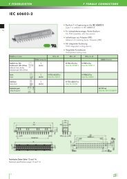
IEC 60603 - 2<br />
IEC 60603 - 2<br />
17 14
E-L17 BUCHSENLEISTEN E-L17 FEMALE CONNECTORS<br />
11 12<br />
Technische Daten Seite 11 und 12.<br />
Technical specifications page 11 and 12.<br />
15
E-L17 BUCHSENLEISTEN E-L17 FEMALE CONNECTORS<br />
Technische Daten Seite 11 und 12.<br />
Technical specifications page 11 and 12.<br />
16
E-L17<br />
E-L17 STIFTLEISTEN<br />
DIN 41617<br />
Technische Daten Seite 14 11 und und 15. 12.<br />
Technical Technical specifications specifications page 14 11 and 15. 12.<br />
17<br />
20<br />
E-L17 MALE CONNECTORS<br />
Mit abgewinkelten Tauchlötanschlüssen<br />
With angled solder pins<br />
Für Leiterplattenmontage<br />
For PCB assembly<br />
Polzahl/no of contacts 13 21 31<br />
Gütekl./mating class<br />
Directive<br />
2002/95/EC<br />
Compliant<br />
90° Tauchlöt 1 (Ag) 01 s13wAg 01 s21wAg 01 s31wAg<br />
90° solder pin Order-No. 010131 Order-No. 010211 Order-No. 010311<br />
2 (Au/Sn) 01 s13w2Sn/Au 01 s21w2Sn/Au 01 s31w2Sn/Au<br />
Order-No. 010132 Order-No. 010212 Order-No. 010312<br />
Polzahl A ± 0.2 B ± 0.1 C1 ± 0.1 C2 ± 0.1 D ± 0.1<br />
No. of pos.<br />
13 45.6 12 x 2.5 = 30 12 x 2.5 = 30 12 x 2.54 = 30.48 40<br />
21 65.6 20 x 2.5 = 50 20 x 2.5 = 50 20 x 2.54 = 50.80 60<br />
31 90.6 30 x 2.5 = 75 30 x 2.5 = 75 30 x 2.54 = 76.20 85
E-L17 MALE CONNECTORS<br />
Mit geraden Tauchlötanschlüssen<br />
With straight solder pins<br />
Für Leiterplattenmontage<br />
For PCB assembly<br />
Technische Daten Seite 11 und 12.<br />
Technische Daten Seite 14 und 15.<br />
Technical specifications page 14 11 and and 15. 12.<br />
E-L17 STIFTLEISTEN<br />
Polzahl/no of contacts 13 21 31<br />
Gütekl./mating class<br />
Tauchlöt gerade 1 (Ag) 01 s13sgAg 01 s21sgAg 01 s31sgAg<br />
solder pin straight Order-No. 013131 Order-No. 013211 Order-No. 013311<br />
2 (Au/Sn) 01 s13sg2Sn/Au 01 s21sg2Sn/Au 01 s31sg2Sn/Au<br />
Order-No. 013132 Order-No. 013212 Order-No. 013312<br />
DIN 41617<br />
Directive<br />
2002/95/EC<br />
Compliant<br />
Polzahl A ± 0.2 B ± 0.1 C ± 0.1 D<br />
No. of pos.<br />
13 44.6 12 x 2.5 = 30 40 35<br />
21 64.6 20 x 2.5 = 50 60 55<br />
31 89.6 30 x 2.5 = 75 85 80<br />
18<br />
21<br />
E-L17
F<br />
F FEDERLEISTEN<br />
IEC 60603-2<br />
DIN 41612 IEC 60603-2<br />
Tauchlöt 6 mm, flach 2 04 Ff32z+dft1x12-co 04 Ff48ft1x12-co<br />
Anschlussraster 5,08 x 5,08 mm (Au/Sn) Order-No. 0423012 Order-No. 0423112<br />
solder pin 6 mm, slim line<br />
termination grid 5.08 x 5.08 mm<br />
Faston 2 04 Ff32z+bfa2,8/2-co 04 Ff48fa2,8/2-co<br />
faston (Au/Sn) Order-No. 042102 Order-No. 042052<br />
Gabelfaston 2 04 Ff32z+dgfa2,8/2-co<br />
faston (fork) (Au/Sn) Order-No. 042162<br />
Technische Daten Seite 13 und 14.<br />
Technische Daten Seite 16 und 17.<br />
Technical Technical specifications specifications page page 16 13 and and 17. 14.<br />
19 22<br />
Directive<br />
2002/95/EC<br />
Compliant<br />
F FEMALE CONNECTORS<br />
Bauform F in Ergänzung an die DIN 41612<br />
Type F in addition to DIN 41612<br />
Für Leiterplattenmontage, flache Bauform<br />
For PCB assembly, slim line version<br />
Isolierkörper aus Polyester (PBT)<br />
Material of insulating body: Polyester (PBT)<br />
Mit integrierter Kodierung<br />
With integrated coding device<br />
Vergoldete Kontaktzone<br />
Gold-plated mating area<br />
Polzahl/no of contacts 32 (z + b) 32 (z + d) 48 (z + b + d)<br />
IEC 60603-2<br />
IEC 60603-2<br />
Gütekl./mating class Zubehör/Accessories<br />
Kodierkeile (grün) 06 F24H7-cod<br />
coding key (green) Order-No. 0401115600C99
Technische Daten Seite 13 und 14.<br />
Technical specifications page 13 and 14.<br />
IEC 60603-2<br />
IEC 60603-2<br />
20
IEC 60603-2<br />
Technische Daten Seite 13 und 14.<br />
Technical specifications page 13 and 14.<br />
21<br />
IEC 60603-2<br />
IEC 60603-2<br />
PC
H15 FEMALE CONNECTORS<br />
IEC 60603-2 DIN 41612<br />
Isolierkörper aus PBT<br />
Material of insulating body: PBT<br />
Anschlussart im Netzeingangsbereich: Faston 6,3 x 0,8 mm<br />
Contacts at input side: faston 6.3 x 0.8 mm<br />
Anschlussart im Ausgangsbereich: Doppelpinkontakte (wahlweise<br />
in Tauchlöt- oder Einpresstechnik)<br />
Contacts at output side: double pin contacts (for either in<br />
solder pin oder press-fit zone)<br />
Einpresszone PbSn-Oberfläche<br />
Press-fit zone PbSn-surface<br />
Polzahl/no of contacts 15<br />
12 Einpreßanschlüsse 1 05 H15/12fdepAg/SnB+3fa-co<br />
(Doppelpin) und (Ag/Sn) Order-No. 0510581<br />
3 Fastonanschlüsse<br />
12 press-fit pins<br />
(double pin) and<br />
3 faston contacts<br />
Kodierkeile (grün) 05 H-cod<br />
coding key (green) Order-No. 0560115600C99<br />
Technische Daten Seite 16 13 und und 17. 14.<br />
Technical Technical specifications specifications page page 16 13 and 17. 14.<br />
H15 FEDERLEISTEN<br />
Gütekl./mating class Zubehör/Accessories<br />
22<br />
27<br />
H15
H15<br />
H15 FEDERLEISTEN<br />
DIN 41612 IEC 60603-2<br />
Polzahl/no of contacts 15<br />
Einpressanschluss 1 05 H15fdepAg/SnB-co<br />
(Doppelpin) (Ag/Sn) Order-No. 0589110<br />
press-fit (double pin)<br />
Technische Daten Seite 16 13 und und 17. 14.<br />
Technical Technical specifications specifications page page 16 13 and 17. 14.<br />
23 28<br />
H15 FEMALE CONNECTORS<br />
Bauform H15 in Ergänzung an die DIN 41612<br />
Type H15 in addition to DIN 41612<br />
Flexible Einpresszone, PbSn-Oberfläche<br />
Flexible press-fit zones, PbSn-surface<br />
Isolierkörper aus PBT<br />
Material of insulating body: PBT<br />
Mit integrierter Kodierung<br />
With integrated coding device<br />
IEC 60603-2<br />
IEC 60603-2<br />
Gütekl./mating class Zubehör/Accessories<br />
Kodierkeile (grün) 05 H-cod<br />
coding key (green) Order-No. 0560115600C99
H15 FEMALE CONNECTORS<br />
H15 FEDERLEISTEN<br />
IEC 60603-2 DIN 41612<br />
Bauform H15 in Ergänzung an die DIN 41612<br />
Type H15 in addition to DIN 41612<br />
Isolierkörper aus PBT<br />
Material of insulating body: PBT<br />
Anschlussart im Netzeingangsbereich: Faston 6,3 x 0,8 mm<br />
Contacts at input side: faston 6.3 x 0.8 mm<br />
Anschlussart im Ausgangsbereich: Doppelpinkontakte (wahlweise<br />
in Tauchlöt- oder Einpresstechnik)<br />
Contacts at output side: double pin contacts (for either in<br />
solder pin oder press-fit zone)<br />
Einpresstechnik<br />
Bei der Einpresstechnik handelt es sich um eine bedingt lösbare, lötfreie Verbindungstechnik, die gedruckte Schaltungen mit<br />
Bauelementen elektrisch und mechanisch verbindet.<br />
Ganz besonders wichtig ist es, auf die Ausführung und die Maße des Bohrloches zu achten. Bei einem zu engen Bohrloch kann<br />
es zur Beschädigung der Kupferhülse im Bohrloch kommen. Bei zu großem Bohrloch können dagegen die Haltekräfte zu gering<br />
sein. Die zulässigen Toleranzen (IEC 352, Teil 5) sind bei der flexiblen Einpresszone (z. B. Bohrung Ø 1,6 ± 0,09) ca. 50 %<br />
größer als bei der massiven Zone.<br />
Press-fit-technology<br />
Press-fit-technology is a limited detachable, solder-free connection which connects printed circuits with components electrically and<br />
mechanically.<br />
It is significant to regard the version and the dimensions of the drill hole. A too narrow drill hole can damage the copper shell<br />
within the drill hole. A too wide drill hole might affect that the retention force is too low. The acceptable tolerances (IEC 352,<br />
part 5) are at the flexible press-fit-zone (e. g. drill hole Ø 1.6 ± 0.09) approx. 50 % higher than at the massive-zone.<br />
Bohrungsmaß/<br />
Drill hole dimension<br />
Prüfmaß/Test dimension:<br />
Elastische Einpresszone/flexible press-fit zone<br />
IEC 60603-2<br />
IEC 60603-2<br />
Prüfmaß/<br />
Test dimension<br />
24 29<br />
H15
H15<br />
H15 FEDERLEISTEN<br />
DIN 41612 IEC 60603-2<br />
Einpresstechnik<br />
Press-fit-technology<br />
Technische Daten<br />
Technical data’s<br />
Kantenradius R = nicht scharfkantig<br />
Edge radius R = not sharp-edged<br />
Zentrierhilfe optimiert auf zentrisches Einpressen<br />
Centring support optimised for centric press-in<br />
Bodenstärke 0,10 – 0,14 mm<br />
Ground strength 0.10 – 0.14 mm<br />
Einpresskraft max. 150 N pro Pin (bei 35 mm/min)<br />
Press-in-force max. 150 N per Pin (at 35 mm/min)<br />
30 25<br />
H15 FEMALE CONNECTORS<br />
Auspresskraft min. 40 N pro Pin (sofort nach Einpressvorgang bei 10 mm/min)<br />
min. 20 N pro Pin (nach allen Belastungsprüfungen und Alterungsversuchen bei 10 mm/min)<br />
Press-out-force min. 40 N per Pin (right after press-in-process at 10 mm/min)<br />
min. 20 N per Pin (after all loading tests and ageing tests at 10 mm/min)<br />
Elastizität min. 0,03 mm (Mittelwert 0,04 mm)<br />
Flexibility min. 0.03 mm (average 0.04 mm)<br />
Leiterplattendicke ab 1,6 mm<br />
PCB thickness from 1.6 mm<br />
Lochaufbau nach DIN 41611, Teil 5 bzw. IEC 352-5<br />
PCB standard hole as per DIN 41611, part 5 respectively DIN IEC 48B(Sec)341
H15 MALE CONNECTORS<br />
H15 MESSERLEISTEN<br />
IEC 60603-2 DIN 41612<br />
Bauform H15 in Ergänzung an die DIN 41612<br />
Type H15 in addition to DIN 41612<br />
Mit integrierter Kodierung<br />
With integrated coding device<br />
Umspritzte Kontakte und geschlossener Isolierkörper<br />
im Anschlussbereich zur Platine<br />
The male connectors with fully shrouded contacts have<br />
a closed insulator to the PCB on termination side<br />
Die Messerleisten sind flussmitteldicht<br />
The male connectors are flux tight<br />
Polzahl/no of contacts 15 14 + 1 13 + 2<br />
Voreilung/extended pin – z32 z4 + z32<br />
90° Tauchlöt 1 (Ag) 05 H15mgwB-co 05 H15mgwvz32B-co 05 H15mgwvz4+32B-co<br />
90° solder pin Sn Order-No. 0510591 Order-No. 0510596<br />
05 H15mgwvz32SnB-co<br />
Order-No. 05105961<br />
Order-No. 05105917<br />
Technische Daten Seite 13 und 14.<br />
Technische Daten Seite 16 und 17.<br />
Technical specifications page 16 13 and and 17. 14.<br />
IEC 60603-2<br />
IEC 60603-2<br />
Directive<br />
2002/95/EC<br />
Compliant<br />
Gütekl./mating class Zubehör/Accessories<br />
26 31<br />
H15
H15<br />
H15 MESSERLEISTEN<br />
DIN 41612 IEC 60603-2<br />
90° Tauchlöt,<br />
1-reihig kurz 1 05 H15mgwvz32/k1<br />
Luft- und Kriechstrecken<br />
im Anschlussbereich<br />
verringert<br />
90° solder pin,<br />
1 in row, slim line<br />
Air leakage and creepage<br />
distance at termination<br />
area reduce<br />
(Ag) Order-No. 0512155<br />
90° Tauchlöt,<br />
2-reihig kurz 1 05 H15mgwvz32/k2<br />
90° solder pin, (Ag) Order-No. 0512160<br />
2 in row, slim line<br />
Technische Daten Seite 13 und 14.<br />
Technische Daten Seite 16 und 17.<br />
Technical specifications page 13 and 14.<br />
Technical specifications page 16 and 17.<br />
32 27<br />
H15 MALE CONNECTORS<br />
Bauform H15 kurz in Ergänzung an die DIN 41612<br />
Type H15 slim line in addition to DIN 41612<br />
Umspritzte Kontakte, geschlossener Isolierkörper im<br />
Anschlussbereich zur Platine und flussmitteldicht<br />
The male connectors with fully shrouded contacts have a<br />
closed insulator for the PCB on termination side and they are<br />
flux tight<br />
Platzersparnis 1-reihige Version bis zu 60 %, 2-reihige Version<br />
bis zu 30 %<br />
The single-row version provides a gain in space of up to 60%,<br />
the 2-row version provides a gain in space of up to 30 %<br />
Polzahl/no of contacts 15 14 + 1 13 + 2<br />
Voreilung/extended pin – z32 z4 + z32<br />
Gütekl./mating class<br />
Directive<br />
2002/95/EC<br />
Compliant<br />
IEC 60603-2<br />
IEC 60603-2
H15 MALE CONNECTORS<br />
IEC 60603-2 DIN 41612<br />
Bauform H15 kurz in Ergänzung an die DIN 41612<br />
Type H15 slim line in addition to DIN 41612<br />
Umspritzte Kontakte und geschlossener Isolierkörper im<br />
Anschlussbereich zur Platine und flussmitteldicht<br />
The male connectors with fully shrouded contacts have a<br />
closed insulator for the PCB on termination side and they are<br />
flux tight<br />
Mit voreilendem Anschlusspin für Netzspannung<br />
With extended pin for line voltage<br />
90° Tauchlöt, 1-reihig kurz mit 1 05 H15mgwvz32/k1-hö30<br />
vorgesetztem Anschluss Pos. 30<br />
Luft- und Kriechstrecken<br />
im Anschlussbereich verringert<br />
90° solder pin, 1 in row<br />
with extended pin at pos. 30<br />
Air leakage and creepage<br />
distance at termination<br />
area reduce<br />
(Ag) Order-No. 0512197<br />
90° Tauchlöt, 1-reihig kurz 1 05 H15mgwvz32/k1-hö30o26<br />
mit vorgesetztem<br />
Anschluss Pos. 30, ohne Pin 26<br />
Luft- und Kriechstrecken<br />
im Anschlussbereich verringert<br />
90° solder pin, 1 in row<br />
with extended pin<br />
at pos. 30 without pin 26<br />
Air leakage and creepage<br />
distance at termination<br />
area reduce<br />
(Ag) Order-No. 0512171<br />
Technische Daten Seite 13 und 14.<br />
Technische Daten Seite 16 und 17.<br />
Technical Technical specifications specifications page page 16 13 and and 17. 14.<br />
IEC 60603-2<br />
IEC 60603-2<br />
H15 MESSERLEISTEN<br />
Polzahl/no of contacts 15 14 + 1 13 + 2<br />
Voreilung/extended pin – z32 z4 + z32<br />
Gütekl./mating class<br />
Directive<br />
2002/95/EC<br />
Compliant<br />
28 33<br />
H15
H11<br />
H11 FEDERLEISTEN<br />
DIN 41612 IEC 60603-2<br />
Polzahl/no of contacts 11<br />
Technische Daten Seite 13 und 14.<br />
Technische Daten Seite 16 und 17.<br />
Technical specifications page 13 and 14.<br />
Technical specifications page 16 and 17.<br />
36<br />
29<br />
Directive<br />
2002/95/EC<br />
Compliant<br />
Faston 6,3 x 0,8 mm 1 05 H11ffa-co<br />
faston 6.3 x 0.8 mm (Ag) Order-No. 058115<br />
Schraubanschluss 1 05 H11fsr-co<br />
screw (Ag) Order-No. 058131<br />
Bauform H11 in Ergänzung an die DIN 41612<br />
Type H11 in addition to DIN 41612<br />
Isolierkörper aus PBT<br />
Material of insulating body: PBT<br />
Mit integrierter Kodierung<br />
With integrated coding device<br />
H11 FEMALE CONNECTORS<br />
IEC 60603-2<br />
IEC 60603-2<br />
Gütekl./mating class Zubehör/Accessories<br />
Kodierkeile (grün) 05 H-cod<br />
coding key (green) Order-No. 0560115600C99
H11 FEMALE CONNECTORS<br />
IEC 60603-2 DIN 41612<br />
Bauform H11 in Ergänzung an die DIN 41612<br />
Type H11 in addition to DIN 41612<br />
Isolierkörper aus PBT<br />
Material of insulating body: PBT<br />
Mit integrierter Kodierung<br />
With integrated coding device<br />
IEC 60603-2<br />
IEC 60603-2<br />
Polzahl/no of contacts 11<br />
Tauchlöt 5,2 mm flach 1 05 H11ft-co<br />
solder pin 5.2 mm slim (Ag) Order-No. 058021<br />
Technische Daten Seite 13 und 14.<br />
Technische Daten Seite 16 und 17.<br />
Technical Technical specifications specifications page page 16 13 and and 17. 14.<br />
H11 FEDERLEISTEN<br />
Gütekl./mating class Zubehör/Accessories<br />
Kodierkeile (grün) 05 H-cod<br />
coding key (green) Order-No. 0560115600C99<br />
Directive<br />
2002/95/EC<br />
Compliant<br />
30 37<br />
H11
H11<br />
H11 MESSERLEISTEN<br />
DIN 41612 IEC 60603-2<br />
90° Tauchlöt 1 05 H11mw-co 05 H11mwv32-co 05 H11mwv2+32-co<br />
90° solder pin (Ag) Order-No. 057115 Order-No. 057125 Order-No. 057035<br />
Technische Daten Seite 13 und 14.<br />
Technische Daten Seite 16 und 17.<br />
Technical specifications page 13 and 14.<br />
Technical specifications page 16 and 17.<br />
38 31<br />
Directive<br />
2002/95/EC<br />
Compliant<br />
H11 MALE CONNECTORS<br />
Bauform H11 in Ergänzung an die DIN 41612<br />
Type H11 in addition to DIN 41612<br />
Isolierkörper aus PBT<br />
Material of insulating body: PBT<br />
Mit integrierter Kodierung<br />
With integrated coding device<br />
Polzahl/no of contacts 11 10 + 1 9 + 2<br />
Voreilung/extended pin – 32 2 + 32<br />
IEC 60603-2<br />
IEC 60603-2<br />
Gütekl./mating class Zubehör/Accessories
F24H7 FEMALE CONNECTORS<br />
IEC 60603-2 DIN 41612<br />
Bauform F24H7 in Ergänzung an die DIN 41612<br />
Type F24H7 in addition to DIN 41612<br />
Für Leiterplattenmontage, flache Bauform<br />
For PCB assembly, slimline versions<br />
Mit integrierter Kodierung<br />
With integrated coding device<br />
Vergoldete Kontaktzone im F-Teil<br />
Gold-plated mating area part F<br />
Kodierkeil für Federleiste mit Kodiermöglichkeit<br />
Coding key for all female connectors with integrated coding device<br />
Polzahl/no of contacts 24 + 7 (z + b + d)<br />
Tauchlöt 6 mm/ F: 2 (Au/Sn) 06 Mf24ft+7ft6/2-co<br />
Tauchlöt 6 mm gerade, flach H: Ag Order-No. 062152<br />
solder pin 6 mm/<br />
solder pin 6 mm straight slimline<br />
Tauchlöt 6 mm/ F: 2 (Au/Sn) 06 Mf24ft+7ft4,5/2-co<br />
Tauchlöt 4,5 mm gerade, flach H: Ag Order-No. 0692061<br />
solder pin 6 mm/<br />
solder pin 4.5 mm straight slimline<br />
Kodierkeile (grün) 06 F24H7-cod<br />
coding key (green) Order-No. 0401115600C99<br />
Technische Daten Seite 13 und 14.<br />
Technische Daten Seite 16 und 17.<br />
Technical Technical specifications specifications page page 16 13 and and 17. 14.<br />
IEC 60603-2<br />
IEC 60603-2<br />
F24H7 FEDERLEISTEN<br />
F-Teil/H-Teil/part F/part H Gütekl./mating class Zubehör/Accessories<br />
Directive<br />
2002/95/EC<br />
Compliant<br />
32 39<br />
F24H7
F24H7<br />
F24H7 FEDERLEISTEN<br />
DIN 41612 IEC 60603-2<br />
Technische Daten Seite 13 und 14.<br />
Technische Daten Seite 16 und 17.<br />
Technical specifications page 16 13 and and 17. 14.<br />
40 33<br />
Directive<br />
2002/95/EC<br />
Compliant<br />
F24H7 FEMALE CONNECTORS<br />
Bauform F24H7 in Ergänzung an die DIN 41612<br />
Type F24H7 in addition to DIN 41612<br />
Mit integrierter Kodierung<br />
With integrated coding device<br />
Vergoldete Kontaktzone im F-Teil<br />
Gold-plated mating area part F<br />
Polzahl/no of contacts 16 + 7 (z + d) 24 + 7 (z + b + d)<br />
F-Teil/H-Teil/part F/part H Gütekl./mating class Zubehör/Accessories<br />
Faston/Faston 6,3 x 0,8 mm F: 2 (Au/Sn) 06 Mf16z+dfa2,8+7fa2 06 Mf24fa2,8+7fa2<br />
faston/faston 6.3 x 0.8 mm H: Ag Order-No. 062032 Order-No. 062022 62022<br />
IEC 60603-2<br />
IEC 60603-2<br />
Kodierkeile (grün) 06 F24H7-cod<br />
coding key (green) Order-No. 0401115600C99
Technische Daten Seite 13 und 14.<br />
Technical specifications page 13 and 14.<br />
IEC 60603-2<br />
IEC 60603-2<br />
34
MSP FEMALE AND MALE CONNECTORS<br />
Modulsteckverbinder 2- und 3-polig<br />
Modular connector 2- and 3-way<br />
Platzsparend<br />
Space saving<br />
Großer Versatzausgleich in y-Ausrichtung<br />
Offset up to +/– 1 mm in y-orientation<br />
Anreihbar<br />
Side-by-side placement<br />
MSP FEDER- UND MESSERLEISTEN<br />
Polzahl/no of contacts 2 3<br />
Gütekl./mating class<br />
Federleiste Tauchlöt 1 22 Mspf2 22 Mspf3<br />
4 mm Doppelpin (Ag) Order-No. 220012 Order-No. 220013<br />
female solder<br />
double pin 4 mm<br />
Messerleiste 90° Tauchlöt 1 22 Mspm2 22 Mspm3<br />
male 90° solder pin (Ag) Order-No. 220022 Order-No. 220023<br />
UL<br />
35<br />
43<br />
MSP
MSP<br />
MSP FEDERLEISTEN MSP FEMALE CONNECTORS<br />
Bauform E-MSP<br />
Type<br />
Maximale Polzahl 2<br />
Maximum contacts 3<br />
Luftstrecken Kontakt zu Kontakt mm > 6,5<br />
Air leakage distance Contact to contact<br />
Kriechstrecken Kontakt zu Kontakt mm > 12,0<br />
Creepage distance Contact to contact<br />
Betriebsstrom bei 20° C<br />
Operating current via at 20° C<br />
A 20<br />
Prüfspannung Ueff Kontakt zu Kontakt V 3100<br />
Test voltage Ueff Contact to contact<br />
Durchgangswiderstand mΩ < 8<br />
Contact resistance<br />
Steck- und Ziehkraft N < 20<br />
Insertion and withdrawal forces < 30<br />
Betriebstemperatur<br />
Operating Temperature temperatur limit<br />
°C – 55 ... + 125<br />
Güteklasse 1 Steckzyklen 500<br />
Quality perfomance category level mating cycles<br />
Isolierkörper Vergleichszahl Kriechwegbildung CTI PBT CTI 275<br />
Insulating body Creeping current<br />
44 36<br />
Brandschutzklasse UL 94 V-0<br />
Flammability Fire resistance<br />
Material PBT 30 % GV<br />
Material<br />
Isolationswiderstand Ω 10 12<br />
Insulating resistance<br />
Kontaktoberfläche Steckbereich Ag<br />
Contact surface Mating area<br />
Anschlussbereich Ag<br />
Termination area
FOKA FOR IGBT MODULES<br />
Dieser Steckverbinder (Formkabel) ist speziell für die Verbindung<br />
von IGBT-Modulen mit einer Leiterplatte entwickelt<br />
worden.<br />
This connector with cable is specially made for connecting<br />
IGBT modules with a PCB.<br />
Einfache und schnelle Montage<br />
Easy and fast mounting<br />
Geeignet für Fastonanschlüsse 2,8 x 0,5 mm<br />
Suitable for Faston tabs 2.8 x 0.5 mm<br />
Der Steckverbinder ist in drei verschiedenen Rastern erhältlich<br />
(4,0 mm; 4,7 mm; 6,0 mm)<br />
The connector is available in three different grids (4.0 mm,<br />
4.7 mm, 6.0 mm)<br />
Weitere Modifikationen auf Anfrage<br />
Further modifications upon request<br />
Formkabel Anwendungsbeispiel<br />
Durch die von <strong>2E</strong> entwickelte Kabelkonfektion für IGBT-Module<br />
müssen diese nicht mehr manuell konfektioniert, sondern werden<br />
einfach und schnell mit der Leiterplatte verbunden. Die Konfek -<br />
tion eignet sich für IGBT-Module mit Faston-Anschlüssen<br />
2,8 x 0,5 mm mit den Rastermaßen 4,0 / 4,7 und 6,0 mm.<br />
Die farbliche Kodierung der Litzen und die Litzenführung sorgen<br />
für eine klare Zuordnung der Polarisierung. Durch die Isolierung<br />
zwischen den Faston-Kontakten werden Kurzschlüsse aus -<br />
geschlossen. Die Konfektion wird über verrastende Lötkontakte<br />
mit der Leiterplatte verbunden und kann in bestehende<br />
Lötprozesse integriert werden.<br />
Auf Anfrage sind kundenspezifische Modifikationen erhältlich.<br />
Application example for IGBT assembly<br />
The cable assemblies for IBGT modules which were developed<br />
by <strong>2E</strong> can be easily and fast connected with the PCB because it<br />
is no necessary anymore to preform them manually. Our cable<br />
assemblies are suitable for IGBT modules with faston contacts<br />
2.8 x 0.5 mm and are available in three different grids<br />
(4.0/4.7/6.0 mm). The coding in colour of the stranded wires<br />
and its guides enables to assign the polarization. Short-circuits<br />
are avoided by insulating between the faston contacts. The<br />
cable assembly is connected with the PCB through locking solder<br />
contacts and can be integrated in already existing solder processes.<br />
Tailor-made modifications are available upon request.<br />
FOKA FÜR IGBT-MODULE<br />
45 37<br />
FOKA
38<br />
Order-No. 4400116400C03
FOKA FOR IGBT MODULES<br />
Bauform Einheit FOKA<br />
Type Unit<br />
FOKA FÜR IGBT-MODULE<br />
Raster 4,0 4,7 6,0<br />
grid<br />
Betriebsspannung zwischen Kontakt 1+ 2 und 3 + 4 V 20<br />
Operating voltage between contact 1+ 2 and 3 + 4<br />
zwischen Kontakt 2 + 3 V 1200<br />
between contact 2 + 3<br />
Betriebsstrom bei 20° C A 2<br />
Operating current at 20° C<br />
Betriebsstrom eff. mA 50<br />
Operating current eff.<br />
Prüfspannung Ueff Kontakt zu Kontakt V 1000<br />
Test voltage Ueff Contact to contact<br />
Kontakt zu Masse V 3000<br />
Contact to ground<br />
Durchgangswiderstand mΩ < 25<br />
Contact resistance<br />
Steckkraft N < 30<br />
Insertion force<br />
Ziehkraft N > 10<br />
Withdrawal forces<br />
Betriebstemperatur °C – 25 ... + 85<br />
Operating temperature<br />
Güteklasse Steckzyklen 10<br />
Mating class mating cycles<br />
Brandschutzklasse Stecker UL 94 V-0<br />
Flammability Connector<br />
Kabel UL 1430<br />
Cable<br />
Kontaktoberfläche Sn<br />
Contact surface<br />
Kontaktmaterial CuSn<br />
Contact material<br />
39<br />
47<br />
FOKA
<strong>2E</strong> <strong>mechatronic</strong> GmbH & Co. KG<br />
narr group<br />
Maria-Merian-Str. 29<br />
73230 Kirchheim unter Teck<br />
Telefon: +49 7021 9301-0 Fax: -70<br />
info@2e-<strong>mechatronic</strong>.de<br />
www.2e-<strong>mechatronic</strong>.de<br />
3. Auflage: Technische Änderungen vorbehalten