Bulkhead Gates.cdr - Rodney Hunt Company
Bulkhead Gates.cdr - Rodney Hunt Company
Bulkhead Gates.cdr - Rodney Hunt Company

You also want an ePaper? Increase the reach of your titles
YUMPU automatically turns print PDFs into web optimized ePapers that Google loves.
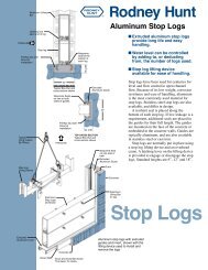
<strong>Bulkhead</strong> <strong>Gates</strong> Specification<br />
1. GENERAL<br />
This specification relates to the design, materials<br />
of construction, fabrication and furnishing of<br />
the bulkhead gate with appurtenant seals,<br />
guides, sills and accessories required for complete<br />
and proper operation of the gates. The<br />
bulkhead gate shall be manufactured by the<br />
<strong>Rodney</strong> <strong>Hunt</strong> <strong>Company</strong> or approved equal.<br />
Manufacturers shall have a minimum of 10<br />
years experience in the design and manufacture<br />
of equipment of this type. Manufacturer shall<br />
submit as a minimum<br />
a list of 10 projects with bulkhead gate installations.<br />
The list shall include project name,<br />
contact, telephone number, years of service,<br />
size and method of operation.<br />
2. MATERIALS<br />
All component parts will be of the type of<br />
material shown and conform to the standards<br />
designated in this section.<br />
Plate or Structural Steel:<br />
ASTM A36, A242, A441 or A599<br />
Stainless Steel:<br />
ASTM A167 or A276, Type 302 or 304<br />
Component Item ASTM Standard<br />
1. Gate Disc Skin Plate Steel Plate<br />
2. Gate Disc Frame Structural<br />
Members Steel<br />
3. Retainer Bars and Stainless<br />
Fasteners for seals Steel<br />
4. Fasteners (Studs, Anchors, Stainless<br />
and Assembly Bolts) Steel<br />
5. Seals Contact Surfaces Stainless<br />
Steel<br />
6. Seals<br />
HY-Q Neoprene D2000, Grade AA625<br />
J-Seal Neoprene D2000, Grade<br />
2BC515<br />
7. Guide Slots Structural<br />
(Prefabricated) Steel<br />
3. DESIGN COMPUTATIONS<br />
A. Gate disc The gate disc shall consist of<br />
a smooth skin plate with horizontal and vertical<br />
structural reinforcing members and shall be<br />
continuously welded throughout to form a boxlike<br />
structure. The gate shall be designed to<br />
safely withstand the maximum unbalanced<br />
head as designated in the gate schedule<br />
without exceeding that submitted by the<br />
Manufacturer and approved by the Engineer.<br />
Approval by the Engineer shall not relieve the<br />
Manufacturer from the responsibility for the<br />
© Copyright 1995 by <strong>Rodney</strong> <strong>Hunt</strong> <strong>Company</strong>.<br />
<strong>Rodney</strong> <strong>Hunt</strong> CompAny<br />
ORANGE, MASSACHUSETTS 01364<br />
TEL: 508-544-2511/FAX: 508-544-7204<br />
adequacy of the design. The disc deflection<br />
shall not exceed 1/360 of the nominal gate<br />
width. A flat bar shall be welded to the outer<br />
periphery of the skin plate to provide a mounting<br />
surface for the gate seals. All steel gate components<br />
shall have a minimum thickness of 5/16”.<br />
B. Seals Resilient seals shall be placed along<br />
the top, bottom, and both sides of the gate to<br />
reduce leakage. The seal attaching hardware<br />
shall be stainless steel and attached in a manner<br />
to permit replacement of the seals. The side<br />
and top seals shall be of the “J” type and the<br />
bottom seal of the flush-bottom type. J-seal<br />
comers shall be formed by continuous molded<br />
sections. Joints between the molded corners<br />
and top and side seals shall be a square butt<br />
type located a minimum of 12” from the corner.<br />
The molded corner shall be bonded to the top<br />
and side seal and assembled to the gate disc<br />
in the manufacturerʼs shop. Mitered joints are<br />
not acceptable.<br />
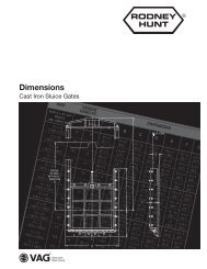
C. Guide slots, Sill, and Header Prefabricated<br />
structural steel guide slots shall be provided.<br />
These shall be to the proper dimensions and<br />
shall include stainless steel seal contact surfaces<br />
on both upstream and downstream faces.<br />
These guides extend twice the height of the<br />
gate above the sill so the gate can be raised<br />
completely out of the flow. The stainless steel<br />
seal contact surface may have maximum roughness<br />
of 125 micro-inch rms. The bottom sill shall<br />
consist of a structural steel beam with a stainless<br />
steel seal contact surface. The header shall<br />
consist of a structural steel angle or formed<br />
steel plate with a stainless steel seating surface.<br />
4. PAINTING<br />
The gate disc and all exposed steel surfaces<br />
shall be blasted to SSPC SP-10.<br />
Hoisting Equipment<br />
Prime: One (1) coat of Amerlock 400<br />
at 5.0 mils thick<br />
Finish: One (1) coat of Amercoat 450HS,<br />
color gray<br />
Immersed Equipment<br />
Prime: One (1) coat of Amerlock 400<br />
at 5.0 mils thick<br />
Finish: One (1) coat of Amerlock 400<br />
at 5.0 mils thick<br />
5. WELDING<br />
All welding will be done in accordance with<br />
AWA D1.1.