Hoisting Equipment - Rodney Hunt Company
Hoisting Equipment - Rodney Hunt Company
Hoisting Equipment - Rodney Hunt Company

Create successful ePaper yourself
Turn your PDF publications into a flip-book with our unique Google optimized e-Paper software.
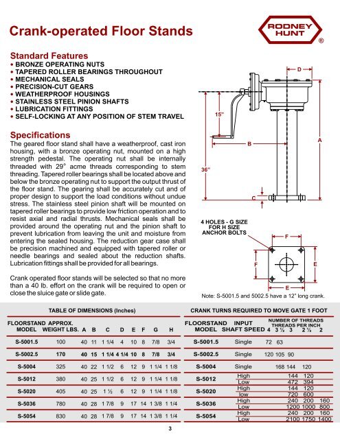
Crank-operated Floor Stands<br />
Standard Features<br />
BRONZE<br />
OPERATING NUTS<br />
TAPERED<br />
ROLLER BEARINGS THROUGHOUT<br />
MECHANICAL<br />
SEALS<br />
PRECISION-CUT<br />
GEARS<br />
WEATHERPROOF<br />
HOUSINGS<br />
STAINLESS<br />
STEEL PINION SHAFTS<br />
LUBRICATION<br />
FITTINGS<br />
SELF-LOCKING<br />
AT ANY POSITION OF STEM TRAVEL<br />
Specifications<br />
The geared floor stand shall have a weatherproof, cast iron<br />
housing, with a bronze operating nut, mounted on a high<br />
strength pedestal. The operating nut shall be internally<br />
threaded with 29 ° acme threads corresponding to stem<br />
threading. Tapered roller bearings shall be located above and<br />
below the bronze operating nut to support the output thrust of<br />
the floor stand. The gearing shall be accurately cut and of<br />
proper design to support the load conditions without undue<br />
stress. The stainless steel pinion shaft will be mounted on<br />
tapered roller bearings to provide low friction operation and to<br />
resist axial and radial thrusts. Mechanical seals shall be<br />
provided around the operating nut and the pinion shaft to<br />
prevent lubrication from leaving the unit and moisture from<br />
entering the sealed housing. The reduction gear case shall<br />
be precision machined and equipped with tapered roller or<br />
needle bearings and sealed about the reduction shafts.<br />
Lubrication fittings shall be provided for all bearings.<br />
Crank operated floor stands will be selected so that no more<br />
than a 40 lb. effort on the crank will be required to open or<br />
close the sluice gate or slide gate.<br />
FLOORSTAND APPROX.<br />
MODEL WEIGHT LBS. A<br />
S-5001.5<br />
S-5002.5<br />
S-5004<br />
S-5012<br />
S-5020<br />
S-5036<br />
S-5054<br />
100<br />
170<br />
325<br />
380<br />
405<br />
780<br />
830<br />
40<br />
40<br />
40<br />
40<br />
40<br />
40<br />
40<br />
B<br />
11<br />
15<br />
22<br />
25<br />
25<br />
28<br />
28<br />
C<br />
1 1/4<br />
1 1/4 4 1/4 10<br />
1 1/2<br />
1 1/2<br />
1 ½<br />
1 7/8<br />
1 7/8<br />
D<br />
4<br />
6<br />
6<br />
6<br />
9<br />
9<br />
E<br />
10<br />
12<br />
12<br />
12<br />
17<br />
17<br />
F<br />
8<br />
8<br />
9<br />
9<br />
9<br />
14<br />
14<br />
G<br />
7/8<br />
7/8<br />
1 1/4<br />
1 1/4<br />
1 1/4<br />
1 3/8<br />
1 3/8<br />
H<br />
3/4<br />
3/4<br />
1 1/8<br />
1 1/8<br />
1 1/8<br />
1 1/4<br />
1 1/4<br />
4 HOLES - G SIZE<br />
FOR H SIZE<br />
ANCHOR BOLTS<br />
®<br />
E<br />
Note: S-5001.5 and 5002.5 have a 12” long crank.<br />
TABLE OF DIMENSIONS (Inches) CRANK TURNS REQUIRED TO MOVE GATE 1 FOOT<br />
3<br />
36”<br />
NUMBER OF THREADS<br />
FLOORSTAND INPUT THREADS PER INCH<br />
MODEL SHAFT SPEED 4 3 ½ 3 2 ½ 2<br />
S-5001.5<br />
S-5002.5<br />
S-5004<br />
S-5012<br />
S-5020<br />
S-5036<br />
S-5054<br />
15”<br />
B<br />
Single<br />
Single<br />
Single<br />
High<br />
Low<br />
High<br />
low<br />
High<br />
Low<br />
High<br />
Low<br />
C<br />
F<br />
72<br />
63<br />
F<br />
120 105 90<br />
168 144<br />
D<br />
144<br />
472<br />
144<br />
720<br />
240<br />
1200<br />
240<br />
2100<br />
120<br />
E<br />
120<br />
394<br />
120<br />
600<br />
200<br />
1000<br />
200<br />
1750<br />
A<br />
160<br />
800<br />
160<br />
1400