Installation, Operation, & Maintenance Manual - Gorbel Inc.
Installation, Operation, & Maintenance Manual - Gorbel Inc.
Installation, Operation, & Maintenance Manual - Gorbel Inc.

You also want an ePaper? Increase the reach of your titles
YUMPU automatically turns print PDFs into web optimized ePapers that Google loves.
STEP 3 - AJ360 BOOM/ARM INSTALLATION<br />
TIP: During Boom/Arm <strong>Installation</strong> leave Arm strapped to Boom as shipped.<br />
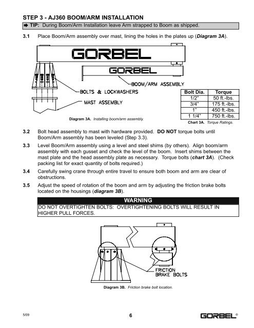
3.1 Place Boom/Arm assembly over mast, lining the holes in the plates up (Diagram 3A).<br />
Diagram 3A. Installing boom/arm assembly.<br />
Chart 3A. Torque Ratings.<br />
3.2 Bolt head assembly to mast with hardware provided. DO NOT torque bolts until<br />
Boom/Arm assembly has been leveled (Step 3.3).<br />
3.3 Level Boom/Arm assembly using a level and steel shims (by others). Align boom/arm<br />
assembly with each gusset and check the level of the boom. Insert shims between the<br />
mast plate and the head assembly plate as necessary. Torque bolts (chart 3A). (Check<br />
packing list for exact quantity of bolts required.)<br />
3.4 Carefully swing crane through entire travel to ensure both boom and arm are clear of<br />
obstructions.<br />
3.5 Adjust the speed of rotation of the boom and arm by adjusting the friction brake bolts<br />
located on the housings (diagram 3B).<br />
WARNING<br />
DO NOT OVERTIGHTEN BOLTS: OVERTIGHTENING BOLTS WILL RESULT IN<br />
HIGHER PULL FORCES.<br />
Diagram 3B. Friction brake bolt location.<br />
Bolt Dia. Torque<br />
1/2” 50 ft.-lbs.<br />
3/4” 175 ft.-lbs.<br />
1” 450 ft.-lbs.<br />
1 1/4” 750 ft.-lbs.<br />
5/09 ®<br />
6