Presentation - Indian Institute of Technology Delhi
Presentation - Indian Institute of Technology Delhi
Presentation - Indian Institute of Technology Delhi

You also want an ePaper? Increase the reach of your titles
YUMPU automatically turns print PDFs into web optimized ePapers that Google loves.
Glass-ceramic seals for SOFC<br />
Development issues in glass-ceramic<br />
seal materials for planar SOFC<br />
stacks<br />
Dr. Rathindra Nath Das<br />
Ceramic Technological <strong>Institute</strong>, Bangalore-560012.<br />
Corp. R&D, BHEL.<br />
mailto: rndas@bhelepd.com<br />
Challenges in Fuel Cell <strong>Technology</strong>,<br />
IIT-<strong>Delhi</strong>, 1-2 December 2006
Rigid seals<br />
Types <strong>of</strong> seals for p-SOFC p SOFC<br />
• Glass and glass–<br />
ceramic sealants,<br />
Brazes<br />
Compressive seals<br />
• Metallic<br />
compressive seals,<br />
Mica-based<br />
compressive seals<br />
Glass-ceramic seals for SOFC<br />
Rigid with embedded phase<br />
•structurally yieldable at high<br />
operating temperatures to<br />
absorb stresses<br />
-increased seal durability & stress absorption
Glass-ceramic seals for SOFC<br />
Typical requirements
Glass-ceramic seals for SOFC<br />
Typical requirements<br />
• Electrical insulation: ρ≥10 4 Ω cm<br />
•Tailored CTE: 9–12 X 10 -6 K -1<br />
•Viscosity<br />
@sealing temp. : 10 6 –10 9 dPa s<br />
@working temp. : ≥ 10 9 dPa s<br />
•Good adherence to :Zirconia, NiYSZ, SS<br />
• flow ability <strong>of</strong> glass for wetting and sealing<br />
• hermetic sealing<br />
• preventing diffusion <strong>of</strong> ions<br />
• no devitrification over a long period <strong>of</strong> time<br />
• Tailoring <strong>of</strong> the bulk properties<br />
• Diffusing the stress arising from thermal and redox<br />
expansions and contractions produced by the system
Glass-ceramic seals for SOFC<br />
The Glass-Ceramics Glass Ceramics Process<br />
Melting and Fritting : homogeneous dispersion, forming shapes<br />
Heat-treatment : converting to microcrystalline ceramics, enhancing<br />
much superior properties than the starting glass<br />
Sealing for IT-SOFC application typically ~850 o C <strong>of</strong><br />
10 6 –10 109 poises*<br />
a glass s<strong>of</strong>tening at ~770 o C<br />
Nucleation invisible growth centers by nucleating agent<br />
10 11<br />
11-10 10 12 poises*<br />
large nos <strong>of</strong> tiny embryos N=10 13 to 10 20 m -3<br />
Crystallisation exothermic effect – DTA, XRD<br />
*viscosity at annealing point is 10<br />
10 13 poises<br />
rate
Example: BCBAS seal composition for SOFC<br />
35BaO–15CaO–5Al 2 O 3 –10B 2 O 3 –35SiO 2 (mol%)<br />
CRYSTALISATION<br />
Glass-ceramic seals for SOFC
Glass-ceramic seals for SOFC<br />
CTE <strong>of</strong> crystalline phases
Glass-ceramic seals for SOFC<br />
Glass-ceramic Glass ceramic families in the SOFC sealing party<br />
System<br />
Typical Composition (mole %)<br />
SiO 2 B 2 O 3 Al 2 O 3 BaO/SrO CaO/MgO Other<br />
Silicate 35 - - 44 Bao 11 Cao 10<br />
Aluminosilicate 50 - 5 45 BaO -<br />
Borate 8 40 7 25 SrO - 20 La 2 O 3<br />
Borosilicate 33 3 - 40 BaO 10 CaO 14<br />
Boroaluminosilicate 33 17 10 35 BaO - 5 La 2 O 3<br />
Boroaluminosilicate<br />
(with alkali)<br />
26.8 40.5 4 - 22.7 CaO 6 K 2 O
Glass-ceramic seals for SOFC<br />
Glass-ceramic Glass ceramic systems for SOFC sealing applications<br />
General formulation from the current patent disclosure:<br />
Component (mol%) Range preferably<br />
Glass-former (SiO2+B2O3) 50-75 60-70<br />
Total Alkalies(K2O+Li2O) less than 10<br />
Alumina (Al2O3) low 2-5<br />
ZrO2, ZnO, TiO2 less than 5 less than 5<br />
High CTE fillers 10-20<br />
(YSZ, Ca-SZ, etc)
Glass-ceramic seals for SOFC<br />
Silicate 35 - - 44 Bao 11 Cao 10<br />
The role <strong>of</strong> Alumina in glass-ceramic compositions<br />
Aluminosilicate 50 - 5 45 BaO -<br />
SiO 2 B 2 O 3 Al 2 O 3 BaO/SrO<br />
Li 2 O<br />
Borate 8 40 7 25 SrO - 20 La 2 O 3<br />
Borosilicate 33 3 - 40 BaO 10 CaO 14<br />
Boroaluminosilicate 33 17 10 35 BaO - 5 La 2 O 3<br />
CTI-1 74.4 - - 23 Li 2 O 1.7 K 2 O 0.8 P 2 O 5<br />
CTI-2 74.2 - 0.3 23 Li 2 O 1.7 K 2 O 0.8 P 2 O 5<br />
CTI-3 73.6 - 1.1 23 Li 2 O 1.7 K 2 O 0.8 P 2 O 5<br />
CTI-4 71.9 - 2.1 23 Li 2 O<br />
CaO/MgO Other<br />
0.8 P 2 O 5<br />
1.7 K 2 O<br />
Boroaluminosilicate<br />
(with alkali) 26.8 40.5 4 - 22.7 CaO 6 K 2 O
Glass-ceramic seals for SOFC<br />
Study <strong>of</strong> complex rheological behavior <strong>of</strong> the microheterogeneous<br />
matrix during heating process
Glass-ceramic seals for SOFC<br />
Study <strong>of</strong> complex rheological behavior <strong>of</strong> the microheterogeneous<br />
matrix during heating process
Variation <strong>of</strong> area<br />
& height <strong>of</strong> the<br />
samples with<br />
increasing<br />
temperatures at<br />
hot stage<br />
microscope<br />
the sintering <strong>of</strong> glass powders<br />
should be completed before<br />
crystallization<br />
Glass-ceramic seals for SOFC
Glass-ceramic seals for SOFC<br />
Study <strong>of</strong> optimum nucleation process by indirect methods
Glass-ceramic seals for SOFC<br />
CTI 1<br />
CTI 2<br />
CTI 3<br />
CTI 4
27 Al MASNMR spectra<br />
<strong>of</strong> the Glass-ceramics<br />
CTI-4 (with 2 mol%<br />
Alumina).<br />
A plot <strong>of</strong> relative<br />
intensities <strong>of</strong><br />
crystobalite and<br />
lithium disilicate<br />
peaks as a function<br />
<strong>of</strong> mol% Alumina).<br />
Glass-ceramic seals for SOFC
Glass-ceramic seals for SOFC<br />
Conclusion<br />
Major glass-ceramic systems used in SOFC sealing<br />
applications are discussed with considerations involved for<br />
selecting batch components and their proportions. Based on<br />
the knowledge <strong>of</strong> the glass-ceramic principles, the processing<br />
conditions may be designed for adequate wetting and sealing<br />
before strengthening the glass by crystallization.
Thank You
Glass-ceramic seals for SOFC<br />
Process Stages<br />
Sealing range<br />
Nucleation<br />
Mg point<br />
Annealing point<br />
Viscosity values<br />
10 2 poises<br />
10 6 –10 109 poises<br />
10 11<br />
11-10 10 12 poises<br />
10 13 poises<br />
Increasing viscosity<br />
back
Silver is an especially useful component in the low-melting-point seal described herein. Silver does not typically form a high<br />
temperature oxide and is therefore stable in an oxidizing environment, such as within a fuel cell stack. Pure silver is s<strong>of</strong>t and yieldable,<br />
and has an appropriate melting temperature, but has a rather high thermal expansion coefficient and does not adhere particularly well<br />
to ceramics. This lack <strong>of</strong> adherence can be addressed by using a wettable layer (350), as described above, or by mixing the silver with<br />
an additive.<br />
0044] One class <strong>of</strong> additives that can be used with silver in a low-melting-point seal are glasses, for example, boro-alumina silicate<br />
glass, boro-baria silicate glass, etc. The glass and silver are mixed to form a composite material. The result is a glass-silver composite<br />
because the two components stay segregated.<br />
[0045] Glass-silver composite seals appear to have excellent wetting and adhesion on both stainless steel and ceramics and result in an<br />
excellent seal. Glasses can be chosen for the composite such that the combined thermal expansion coefficient matches the housing<br />
(100), manifold and/or fuel cell (320).<br />
In FIG. 3B, a seal (360') is made from a glass-silver composite material in which there is a glass matrix (370) and silver (380) as a<br />
discontinuous embedded phase. Such a seal (360') has many advantages including better heat transfer, greater compliance, and a<br />
greater range <strong>of</strong> glass chemistry through thermal expansion coefficient matching with the help <strong>of</strong> the high-expansion silver. Other<br />
conductive metals, as mentioned herein, may also be used in the seal <strong>of</strong> FIG. 3B as the embedded phase, in place <strong>of</strong> silver.<br />
[0048] Additionally, as mentioned above, the low-melting-point seal (360') may also include any number <strong>of</strong> particles, fibers, rods,<br />
spheres or other forms <strong>of</strong> "filler material." This "filler material" may be incorporated in the low-melting-point seal (360') in order to<br />
more closely match the thermal coefficient <strong>of</strong> expansion (TCE) <strong>of</strong> the seal with the TCE <strong>of</strong> the fuel cell housing (100) or other<br />
materials that may be surrounding the fuel cell. Moreover, the "filler material" may also provide additional surface tension to keep the<br />
seal (360') in place when the SOFC operates above the melting point temperature <strong>of</strong> the low-melting-point seal (360). The "filler<br />
material" may be any number <strong>of</strong> conductive or insulating materials including, but in no way limited to, tungsten (W), molybdenum<br />
(Mo), zirconium di-oxide (ZrO.sub.2), magnesium oxide (MgO) or cerium oxide (CeO.sub.2).<br />
While the construction <strong>of</strong> the SOFC housings (100; FIG. 3) using stainless steels and other less expensive materials is advantageous in<br />
reducing the overall cost <strong>of</strong> SOFC stacks, these materials suffer from differing thermal conductivities and thermal coefficients <strong>of</strong><br />
expansion (TCE). As a result, non-uniform thermal expansions <strong>of</strong>ten occur when the housings are placed in stack configurations. Nonuniform<br />
thermal expansion <strong>of</strong> the SOFC housings may produce thermal stresses. These thermal stresses have traditionally been<br />
transferred from the housings, through rigid seals, and onto the SOFCs. The transfer <strong>of</strong> thermal stresses reduces the operating life <strong>of</strong><br />
the SOFC systems by either causing failure in the SOFC, failure in the rigid seals, or both. However, when thermal stresses caused by<br />
the expansion and contraction <strong>of</strong> the metalized areas are transferred to the present low-melting-point seal, the liquid or s<strong>of</strong>tened alloy<br />
<strong>of</strong> the low-melting-point seal yields in response to the thermal stresses (step 640). By yielding in response to thermal stresses, the<br />
present low-melting-point seal prevents the transfer <strong>of</strong> the thermal stresses from the SOFC housing to the somewhat brittle SOFC. This<br />
yielding in response to thermal stresses continues until the reaction cycle ceases and the operating temperature <strong>of</strong> the SOFC housing is<br />
reduced to its original temperature (step 650). As the temperature is decreased, the low-melting-point composite material re-solidifies<br />
into its original position and structure.
Glass-ceramic seals for SOFC<br />
Even if the coefficients <strong>of</strong> thermal expansion are matched, the rates <strong>of</strong> thermal conductivities within a stack are typically not matched,<br />
resulting in non-uniform thermal expansion. As glass is inherently brittle, it cracks and fails under thermal cycling conditions. The brittleness<br />
<strong>of</strong> glass also makes glass seals subject to failure as a result <strong>of</strong> jarring shocks or vibrations.<br />
The fibres may be randomly oriented. In a preferred embodiment, the seal may be precompressed prior to use.<br />
[0009] The ceramic fibres may be selected from the group comprising alumina, zirconia, titania, magnesia or silica. The solid particles may<br />
be ceramic particles, glass particles or other inert materials able to resist degradation and sintering at the operating temperatures <strong>of</strong> the SOFC<br />
stack. If the particles are ceramic particles, the particles may be selected from the group comprising alumina, zirconia, titania, magnesia or<br />
silica.<br />
[0010] In one embodiment, a substantial portion or all <strong>of</strong> the particles are submicronic ceramic particles. Preferably, the particles have a<br />
particle size <strong>of</strong> about 0.50 .mu.m or less. More preferably, the ceramic particles comprise a first portion and a second portion wherein the<br />
particle size <strong>of</strong> the first portion is larger than the particle size <strong>of</strong> the second portion. The first portion may have a particle size <strong>of</strong> about 0.50<br />
.mu.m and the second portion may have a particle size <strong>of</strong> about 0.17 .mu.m or less. In another embodiment, the first portion may have a<br />
particle size <strong>of</strong> about 0.50 .mu.m and the second portion may have a particle size <strong>of</strong> less than about 0.06 .mu.m. The proportion <strong>of</strong> larger<br />
particles to smaller particles may be varied to achieve maximum sealing performance.
Glass-ceramic seals for SOFC<br />
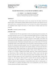
One <strong>of</strong> the major challenges for implementation <strong>of</strong> solid oxide fuel cells (SOFCs) is the development <strong>of</strong><br />
suitable sealant materials to separate the air and fuel. The majority <strong>of</strong> the planner SOFC stacks require<br />
hermetic sealing under stringent environmental conditions to prevent gas leakage or cross-leakage. Some<br />
specific glass-ceramics seals appear promising after reportedly withstanding in excess <strong>of</strong> 1000 hours run<br />
without degradation in SOFC stack demonstrations. Apart from the constituents <strong>of</strong> the residual glass-matrix,<br />
the nature and amount <strong>of</strong> crystalline phases to be nucleated and grown in the glass-ceramic seals have the most<br />
significant bearing on the key characteristics <strong>of</strong> the seal namely thermal expansion match, preventing<br />
diffusion <strong>of</strong> ions, s<strong>of</strong>tening temperature and the flow ability <strong>of</strong> glass for wetting and sealing the cell parts.<br />
Tailoring <strong>of</strong> the bulk properties <strong>of</strong> the seal is achieved by some established tools prescribed in the science and<br />
technology <strong>of</strong> glass-ceramics. These principles with practical examples will be discussed in this talk in relation<br />
to the issues connected to SOFC sealing;<br />
• glass-ceramic system design for electrically insulating seals having chemical and<br />
mechanical compatibility with cell components under oxidizing and reducing<br />
conditions<br />
• choices <strong>of</strong> crystalline phases for tuning <strong>of</strong> bulk coefficient <strong>of</strong> thermal expansion<br />
(CTE) and the expansion pr<strong>of</strong>ile<br />
• influence <strong>of</strong> stabilization <strong>of</strong> phases, solid solution, phase separation, nucleation,<br />
crystallization kinetics, additives and specific ratios<br />
• key processing considerations while selecting melting or glass powder sintering<br />
route, s<strong>of</strong>tening points, designing adequate gaps between wetting, nucleation and<br />
crystallization temperatures.
Glass-ceramic seals for SOFC<br />
Two major approaches are typically utilized in solid oxide fuel cell sealing practice, namely glass ceramic-based chemical seals and<br />
gasket-based mechanical compressive seals. The mechanical compressive seals require a high degree <strong>of</strong> surface preparation and<br />
finish and high-pressure load capacity. A complete hermetic seal <strong>of</strong>tentimes cannot be achieved due to the flatness limitation <strong>of</strong> high<br />
temperature sintered ceramic cell. Also, contact stresses can readily cause cell fracture during assembly and thermal cycling in<br />
SOFC stack operation. Representative examples <strong>of</strong> mechanical type seals are described and illustrated in U.S. publication No.<br />
2002/0195778, 2003/0203267 and 2003/0215689. Additional examples are set forth in WO 2003/036745 A2, WO 2003/032420 A2<br />
and WO/0217416 A2.<br />
Glass- and glass ceramic-based seals have very good wetting and bonding properties to both ceramic and metals and are capable <strong>of</strong><br />
forming hermetic seals. Representative examples <strong>of</strong> this type <strong>of</strong> sealing for solid oxide fuel cells include U.S. Pat. Nos. 6,291,092,<br />
6,271,158, 6,541,146 and 6,656,625. Additionally EP Publication No. 1211230 A1 discloses a glass matrix composition.