TRIBOLOGICAL PROPERTIES OF CARBON ... - Ceramics-Silikaty
TRIBOLOGICAL PROPERTIES OF CARBON ... - Ceramics-Silikaty
TRIBOLOGICAL PROPERTIES OF CARBON ... - Ceramics-Silikaty

You also want an ePaper? Increase the reach of your titles
YUMPU automatically turns print PDFs into web optimized ePapers that Google loves.
Full volume of sphere path is given as:<br />
V0 = 2πR[r 2 ·sin -1 (d/2r) - (d/4)(4r 2 - d 2 ) 1/2 ] (mm 3 ) (2)<br />
where R is wear track radius.<br />
The wear volume normalised for full path and<br />
working force (specific wear) can be written as:<br />
(mm3 V0<br />
w<br />
/Nm) (3)<br />
2 =<br />
l • F<br />
l being the full path of sphere [m], F applied force [N].<br />
During the wear test, we used a constant load of<br />
15 N, the rotation rate was 150 rpm, the radius of the<br />
path was 2 mm, the velocity of sliding was 0.04 m/s,<br />
and the test was stopped after 4000 revolutions. The<br />
path radius r and the number of revolutions n define the<br />
full path and the time needed for the test. In this way,<br />
the full path of the pin on the sample was about 38 m.<br />
ÈSN 19436 tool steel (ISO 41 9436) with hardness<br />
62 HRC and surface roughness with Ra = 0.01-0.013 µm<br />
was used for the spherical pin, the diameter of the pin<br />
being 6 mm.<br />
The full test schedule was as follows:<br />
1. ultrasonic cleaning;<br />
2. measurement of the sample roughness by profilometer<br />
(TALYSURF 6,Taylor-Hobson Ltd., U.K.);<br />
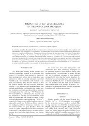
Figure 2. Detail cutting mark of the pin path.<br />
Tolde Z., Starý V., Kubart T.<br />
3. tribometric test;<br />
4. ultrasonic cleaning;<br />
5. measurement of path profiles, using the TALYSURF<br />
6 profilometer. Measurement proceeded parallel with<br />
the composite fibres, and the shape of the surface was<br />
graphically written in a suitable and known scale. In<br />
this profile we estimated the start and end of the profile<br />
of the cutting mark of the pin path. Then its width<br />
and depth were manually measured.<br />
6. test of microhardness.<br />
After the test, the surface of the samples and of the<br />
spherical pin were observed in SEM (Figure 2). Also,<br />
the Vickers microhardness was measured using the<br />
microhardness tester (SHIMADZU, Japan, HMV - 2).<br />
Examples of the measurement output records are shown<br />
in Figure 3.<br />
RESULTS<br />
The experimental results of the roughness measurements<br />
are given in Table 2. Parameters Ra (mean roughness),<br />
Rtm (maximum roughness value), Rq (root mean<br />
square - parameter corresponding to Ra) and S (mean<br />
spacing of the measured adjacent local peaks) are presented<br />
in Table 2. Tables 3 and 4 summarize the results<br />
of measurements of the friction coefficient and of<br />
the wear of C–C and PyC/C–C samples, respectively.<br />
Table 2. Initial values of the roughness parameters; average values of three measurement.<br />
SET Ra Standard Rtm Standard Rq Standard S Standard<br />
No. (µm) deviation (µm) deviation (µm) deviation (µm) deviation<br />
I 7.17 0.28 38.00 2.16 9.77 0.16 49 13<br />
II 5.40 0.86 29.00 4.08 8.57 0.51 180 65<br />
III 8.03 0.41 37.33 2.86 10.93 0.86 70 32<br />
IV 3.10 0.32 19.33 2.35 5.23 0.66 81 22<br />
0.17<br />
0.16<br />
0.15<br />
0.14<br />
0.13<br />
0.12<br />
0.11<br />
0.10<br />
0.09<br />
0.08<br />
0.07<br />
0.06<br />
0 500 1000 1500 2000 2500 3000 3500 4000<br />
Cycles<br />
40 <strong>Ceramics</strong> − Silikáty 52 (1) 37-44 (2008)<br />
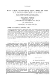
Friction coefficient<br />
Set IV<br />
Set I<br />
Set III<br />
Set II<br />
Figure 3. Time dependence of the average values of the friction<br />
coefficient from three measurements for each set of samples.