Homework set 2 solution(pdf file) - University of Wisconsin-Madison
Homework set 2 solution(pdf file) - University of Wisconsin-Madison
Homework set 2 solution(pdf file) - University of Wisconsin-Madison

Create successful ePaper yourself
Turn your PDF publications into a flip-book with our unique Google optimized e-Paper software.
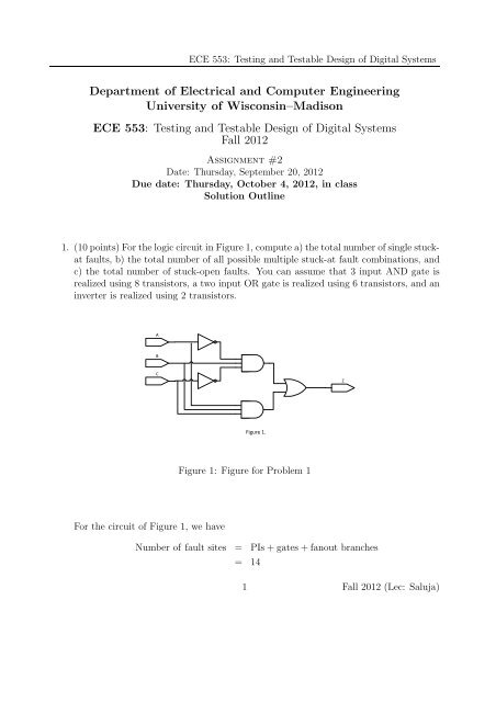
ECE 553: Testing and Testable Design <strong>of</strong> Digital Systems<br />
Department <strong>of</strong> Electrical and Computer Engineering<br />
<strong>University</strong> <strong>of</strong> <strong>Wisconsin</strong>–<strong>Madison</strong><br />
ECE 553: Testing and Testable Design <strong>of</strong> Digital Systems<br />
Fall 2012<br />
Assignment #2<br />
Date: Thursday, September 20, 2012<br />
Due date: Thursday, October 4, 2012, in class<br />
Solution Outline<br />
1. (10points)ForthelogiccircuitinFigure1,computea)thetotalnumber<strong>of</strong>singlestuckat<br />
faults, b) the total number <strong>of</strong> all possible multiple stuck-at fault combinations, and<br />
c) the total number <strong>of</strong> stuck-open faults. You can assume that 3 input AND gate is<br />
realized using 8 transistors, a two input OR gate is realized using 6 transistors, and an<br />
inverter is realized using 2 transistors.<br />
For the circuit <strong>of</strong> Figure 1, we have<br />
A<br />
B<br />
C<br />
Figure 1.<br />
Figure 1: Figure for Problem 1<br />
Number <strong>of</strong> fault sites = PIs+gates+fanout branches<br />
= 14<br />
1 Fall 2012 (Lec: Saluja)<br />
Z
Therefore,<br />
ECE 553: Testing and Testable Design <strong>of</strong> Digital Systems<br />
Number <strong>of</strong> single faults = 14×2<br />
= 28<br />
Number <strong>of</strong> single and multiple faults = 3 number <strong>of</strong> fault sites −1<br />
= 3 14 −1 = 4782968<br />
The circuit has 4,782,968 single and multiple stuck-at faults.<br />
Total number <strong>of</strong> transitors = 26<br />
Therefore the circuit has 26 stuck-open faults.<br />
2. (15 points) (Bushnell and Agrawal) Problem 4.5<br />
(a) A two-input NAND gate is shown in the figure associated with this problem. The<br />
A<br />
B<br />
P1<br />
V<br />
DD<br />
P2<br />
N1<br />
N2<br />
Ground<br />
CMOS NAND gate.<br />
C<br />
A<br />
B<br />
Circuit for Problem 4.5.<br />
Logic NAND gate.<br />
following table gives tests for transistor stuck-open (sop) faults:<br />
Test No. Fault Test: Vector 1, Vector 2<br />
1 P1 sop 11, 01<br />
2 P2 sop 11, 10<br />
3 N1 sop 01, 11 or 10, 11 or 00, 11<br />
4 N2 sop 01, 11 or 10, 11 or 00, 11<br />
Notice that the sop faults <strong>of</strong> N1 and N2 have exactly the same tests. These two faults<br />
are equivalent. Equivalence <strong>of</strong> transistor faults is discussed in the following paper:<br />
2 Fall 2012 (Lec: Saluja)<br />
C
ECE 553: Testing and Testable Design <strong>of</strong> Digital Systems<br />
M.-LFlottes, C.LandraultandS.Provossoudovitch, “FaultModelingandFaultEquivalence<br />
in CMOS Technology,” J. Electronic Testing: Theory and Applications, vol. 2,<br />
pp. 229-241, August 1991.<br />
(b) The following sequence <strong>of</strong> four vectors contains one vector pair for each fault in the<br />
above table:<br />
11, 01, 11, 10<br />
Notice that this sequence also detects all single stuck-at faults in the logic model <strong>of</strong><br />
the NAND gate.<br />
(c) A stuck-at fault in a signal affects two transistors in the two-input NAND gate. For<br />
example, the fault A s-a-1 will mean that N1 remains permanently shorted (N1-ssh)<br />
and P1 remains permanently open (P1-sop). The following table gives all equivalences:<br />
Stuck-at fault Equivalent transistor faults<br />
A s-a-1 N2-ssh and P1-sop<br />
B s-a-1 N1-ssh and P2-sop<br />
C s-a-1 (P1 or P2 or both ssh ) and (N1 or N2 or both sop)<br />
A s-a-0 N2-sop and P1-ssh<br />
B s-a-0 N1-sop and P2-ssh<br />
C s-a-0 N1-ssh and N2-ssh and P1-sop and P2-sop<br />
Notice that the three equivalent faults, A s-a-0, B s-a-0 and C s-a-0, are actually<br />
caused by different faulty transistors. They are detected by the same test (11).<br />
3. (10 points) Show that the two faults c s-a-0 and f s-a-1 are equivalent in the circuit <strong>of</strong><br />
Figure 2.<br />
Faulty functions for the circuit for this problem corresponding to the two faults are:<br />
m(c s−a−0) = b+ab = a+b<br />
n(c s−a−0) = (b+ab)j = (a+b)j<br />
m(f s−a−1) = a+a+b = a+ab = a+b<br />
n(f s−a−1) = (a+a+b)j = (a+ab)j = (a+b)j<br />
The two faulty functions are indistinguishable and hence the two faults are equivalent.<br />
(1)<br />
(2)<br />
3 Fall 2012 (Lec: Saluja)
¡<br />
¢<br />
£<br />
¤<br />
¨<br />
¥<br />
¦<br />
ECE 553: Testing and Testable Design <strong>of</strong> Digital Systems<br />
<br />
©<br />
Figure 2: Figure for Problem 3<br />
4. (35 points) For this problem you will use the circuit given in Figure 3.<br />
A<br />
B<br />
C<br />
D<br />
2<br />
3<br />
1<br />
5<br />
6<br />
8 9<br />
10<br />
11<br />
7<br />
4 12<br />
Figure 3: Figure for Problem 4<br />
13<br />
(a) The Table 1 gives a fault list for the circuit <strong>of</strong> Figure 3, after equivalence fault<br />
collapsing. Fill in the blanks with equivalent fault <strong>set</strong>s for each listed fault.<br />
(Validity check: the total number <strong>of</strong> faults in table should be 38)<br />
(b) Assume that you are applying exhaustive test <strong>set</strong> for the circuit in Figure 2. In<br />
the Table 2, mark all the faults that are detected by each vector. Note that only<br />
14<br />
§<br />
16<br />
17<br />
15<br />
<br />
<br />
18<br />
19<br />
4 Fall 2012 (Lec: Saluja)
ECE 553: Testing and Testable Design <strong>of</strong> Digital Systems<br />
the collapsed faults are listed in Table 2. For this problem you are allowed to use<br />
fault simulator (SFSP) <strong>of</strong> TESTCAD tool<strong>set</strong><br />
(c) From the cover table <strong>of</strong> (b),<br />
i. find minimum number <strong>of</strong> vectors that detect all detectable faults.<br />
ii. list a minimum test <strong>set</strong>.<br />
The completed table for equivelence fautls is:<br />
5 Fall 2012 (Lec: Saluja)
ECE 553: Testing and Testable Design <strong>of</strong> Digital Systems<br />
Fault List all equivalent Faults<br />
1/0 Ø<br />
1/1 7/1 , 5/1, 13/0, 16/0, 18/0<br />
2/0 Ø<br />
2/1 Ø<br />
5/0 Ø<br />
6/0 Ø<br />
6/1 3/1, 8/0<br />
3/0 Ø<br />
4/0 Ø<br />
4/1 Ø<br />
7/0 13/1<br />
8/1 Ø<br />
9/0 11/0, 14/0<br />
9/1 Ø<br />
10/0 12/0,15/1,17/1,19/0<br />
10/1 Ø<br />
11/1 Ø<br />
12/1 Ø<br />
14/1 Ø<br />
15/0 Ø<br />
16/1 Ø<br />
17/0 Ø<br />
18/1 Ø<br />
19/1 Ø<br />
Table 1: Table for problem 4(a)<br />
6 Fall 2012 (Lec: Saluja)
ECE 553: Testing and Testable Design <strong>of</strong> Digital Systems<br />
The completed table <strong>of</strong> the problem 4b is given below. Note that only the collapsed<br />
faults are listed in Table 2.<br />
From the cover table <strong>of</strong> (b),<br />
At least 5 vectors are required to detect all detectable faults.<br />
There are 5 essential vectors, that are<br />
0000,0001,0011,0101 and 1001<br />
to detect all detectable faults. There are however a few faults 5/0, 10/0 and 6/0 and<br />
their equivalent faults that are undetectable.<br />
7 Fall 2012 (Lec: Saluja)
ECE 553: Testing and Testable Design <strong>of</strong> Digital Systems<br />
1 0 0 0 0 0 0 0 0 1 1 1 1 1 1 1 1<br />
2 0 0 0 0 1 1 1 1 0 0 0 0 1 1 1 1<br />
3 0 0 1 1 0 0 1 1 0 0 1 1 0 0 1 1<br />
4 0 1 0 1 0 1 0 1 0 1 0 1 0 1 0 1<br />
1/0 v<br />
1/1 v<br />
2/0 v<br />
2/1 v<br />
5/0<br />
6/0<br />
6/1 v v<br />
3/0 v<br />
4/0 v<br />
4/1 v<br />
7/0 v<br />
8/1 v<br />
9/0 v v<br />
9/1 v<br />
10/0<br />
10/1 v v v v v v v<br />
11/1 v<br />
12/1 v<br />
14/1 v v v v<br />
15/0 v v v v v v v v v v v v v v<br />
16/1 v v v<br />
17/0 v<br />
18/1 v v v v v v v v v v v v v v v<br />
19/1 v v v v v v v v v v v v v v v v<br />
Table 2: Table for problem 4(b)<br />
8 Fall 2012 (Lec: Saluja)
5. (Bushnell and Agrawal) Problem 4.11<br />
ECE 553: Testing and Testable Design <strong>of</strong> Digital Systems<br />
(a)Thegivencircuit isshownbelowwithfaultsitesmarkedwithnumbers. Thenumber<br />
<strong>of</strong> potential fault sites is 18.<br />
sa0<br />
1 sa1<br />
2<br />
sa0<br />
sa1<br />
3<br />
sa0<br />
sa1<br />
sa0<br />
sa1<br />
4<br />
sa0<br />
sa1<br />
5<br />
sa0<br />
sa1<br />
6<br />
sa0<br />
8<br />
sa1<br />
9<br />
sa0<br />
sa1<br />
10<br />
sa0<br />
sa1<br />
12<br />
sa0<br />
sa1<br />
sa0<br />
sa1<br />
13<br />
7<br />
sa0<br />
sa1<br />
sa0<br />
sa1<br />
11<br />
sa0<br />
sa1<br />
15<br />
16<br />
sa0<br />
sa1<br />
Circuit for Problem 4.11.<br />
17<br />
sa0<br />
sa1<br />
14<br />
sa0<br />
sa1<br />
Deleted due to<br />
equivalence<br />
(b) The figure shows deletion <strong>of</strong> equivalent faults using an output to input pass. Of<br />
the 36 faults, 20 remain, giving a collapse ratio 20/36 = 0.56.<br />
(c) Checkpoint lines are shown in boldface numbers. These are three PIs and seven<br />
fanout branches. There are ten checkpoints and 20 checkpoint faults. (There are some<br />
people treated a single input gate (inverter) as continuation <strong>of</strong> its input line. Thus, line<br />
2 is assumed to fanout to 5, 12 and 13. There are nine checkpoints and 18 checkpoint<br />
faults. For grading, I give full credit for both cases.) Further, s-a-0 faults on lines 6<br />
and 12 are equivalent and any one <strong>of</strong> them can be chosen. Similarly, s-a-0 faults on 7<br />
and 13 are equivalent, and so are s-a-0 on 5 and s-a-0 on 11. Thus, the <strong>set</strong> <strong>of</strong> fault <strong>set</strong><br />
is reduced to 17, giving a collapse ratio 17/36 = 0.472.<br />
6. (10 points) (Bushnell and Agrawal) Problem 4.12.<br />
Please use the definition given in the text (Definition 4.7 on page 78) for checkpoints in<br />
a circuit. Note : For those who have older version <strong>of</strong> text, the definision <strong>of</strong> check point<br />
is slightly modified as follows. Checkpoints : Primary inputs and fanout branches <strong>of</strong><br />
a combinational circuit consisting only <strong>of</strong> BOOLEAN gates are called the checkpoints.<br />
Thus, expend XOR gate as in Figure 4.9 in the text.<br />
(a) To find checkpoints <strong>of</strong> the circuit <strong>of</strong> Figure 4.12 in the text, we must replace the<br />
exclusive-OR (XOR) function by a primitive Boolean gate implementation. AND,<br />
OR, NAND, NOR and NOT are called the primitive Boolean gates. Functions such<br />
as XOR are sometimes referred to as complex gates. In the following figure, we have<br />
18<br />
sa0<br />
sa1<br />
9 Fall 2012 (Lec: Saluja)
ECE 553: Testing and Testable Design <strong>of</strong> Digital Systems<br />
assumed one such implementation. Our result is, therefore, based on this assumption.<br />
Other implementations <strong>of</strong> the XOR function are possible and can give a different <strong>set</strong><br />
<strong>of</strong> checkpoints.<br />
c<br />
a<br />
b<br />
d<br />
e<br />
f<br />
g<br />
e1<br />
d2<br />
d1<br />
e2<br />
XOR<br />
There are nine checkpoints in this circuit. These include three primary inputs, a, b and<br />
c, and six fanout branches, d1, d2, f, e1, e2 and g. The checkpoint fault <strong>set</strong> consists<br />
<strong>of</strong> eighteen faults – s-a-0 and s-a-1 faults on the nine lines.<br />
Notice that lines d and e <strong>of</strong> the original circuit are not checkpoints. If we did not model<br />
the XOR block with Boolean gates, then those lines will appear to be checkpoints,<br />
whose number will be fourteen. However, detection <strong>of</strong> those faults will not guarantee<br />
detection <strong>of</strong> faults on the fanouts that are internal to the XOR block. Considering<br />
the Boolean gate structure, a fault on d corresponds to a simultaneous (multiple) fault<br />
on d1 and d2 and, in general, the detection <strong>of</strong> a multiple fault is not equivalent to<br />
detection <strong>of</strong> the component faults.<br />
(b) We evaluate the output function k corresponding to the two faults:<br />
k(d s−a−0) = c+b+a+b<br />
i<br />
h<br />
= c+b+ab<br />
k(g s−a−1) = c+ab+ab+a<br />
= c+ab+a<br />
The two faulty functions are shown by Karnaugh maps below. In both cases, the<br />
functions have exactly one false minterm, abc. Since the two faulty functions are<br />
identical the corresponding faults are equivalent.<br />
Note: this type <strong>of</strong> fault equivalence is functional and is <strong>of</strong>ten difficult to find by typical<br />
fault analysis tools, which rely on structurally identifiable equivalences.<br />
7. (10 points) (Bushnell and Agrawal) Problem 5.26.<br />
10 Fall 2012 (Lec: Saluja)<br />
k
false minterm<br />
b<br />
a<br />
c<br />
k with d s-a-0<br />
ECE 553: Testing and Testable Design <strong>of</strong> Digital Systems<br />
b<br />
ab<br />
c<br />
false minterm<br />
ab<br />
a<br />
b<br />
c<br />
a<br />
k with g s-a-1<br />
(Compute the range <strong>of</strong> fault coverage with 99.7% confidence limit) Assuming that the<br />
fault sample size is much smaller than the total fault population, i.e., Ns ≪ Np, we<br />
use the result <strong>of</strong> Equation 5.9 (page 124 in the book), which can be written as,<br />
Sample size, Ns = 4.52<br />
0.44x(1−x)<br />
∆2 where ±∆ is the 3σ range <strong>of</strong> the coverage estimate and x is the sample coverage. Using<br />
the given data, ∆ = 0.02 and x = 0.70, we obtain<br />
Ns = 4.52 ×0.44×0.7×0.3<br />
0.02 2<br />
= 4,678 faults<br />
11 Fall 2012 (Lec: Saluja)<br />
c