Automated Inspection of Defects in Glass by proper Color space ...
Automated Inspection of Defects in Glass by proper Color space ...
Automated Inspection of Defects in Glass by proper Color space ...

You also want an ePaper? Increase the reach of your titles
YUMPU automatically turns print PDFs into web optimized ePapers that Google loves.
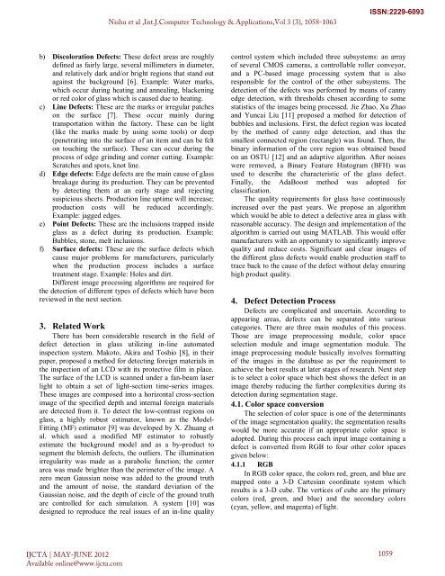
) Discoloration <strong>Defects</strong>: These defect areas are roughly<br />
def<strong>in</strong>ed as fairly large, several millimeters <strong>in</strong> diameter,<br />
and relatively dark and/or bright regions that stand out<br />
aga<strong>in</strong>st the background [6]. Example: Water marks,<br />
which occur dur<strong>in</strong>g heat<strong>in</strong>g and anneal<strong>in</strong>g, blacken<strong>in</strong>g<br />
or red color <strong>of</strong> glass which is caused due to heat<strong>in</strong>g.<br />
c) L<strong>in</strong>e <strong>Defects</strong>: These are the marks or irregular patches<br />
on the surface [7]. These occur ma<strong>in</strong>ly dur<strong>in</strong>g<br />
transportation with<strong>in</strong> the factory. These can be light<br />
(like the marks made <strong>by</strong> us<strong>in</strong>g some tools) or deep<br />
(penetrat<strong>in</strong>g <strong>in</strong>to the surface <strong>of</strong> an item and can be felt<br />
on touch<strong>in</strong>g the surface). These can occur dur<strong>in</strong>g the<br />
process <strong>of</strong> edge gr<strong>in</strong>d<strong>in</strong>g and corner cutt<strong>in</strong>g. Example:<br />
Scratches and spots, knot l<strong>in</strong>e.<br />
d) Edge defects: Edge defects are the ma<strong>in</strong> cause <strong>of</strong> glass<br />
breakage dur<strong>in</strong>g its production. They can be prevented<br />
<strong>by</strong> detect<strong>in</strong>g them at an early stage and reject<strong>in</strong>g<br />
suspicious sheets. Production l<strong>in</strong>e uptime will <strong>in</strong>crease;<br />
production costs will be reduced accord<strong>in</strong>gly.<br />
Example: jagged edges.<br />
e) Po<strong>in</strong>t <strong>Defects</strong>: These are the <strong>in</strong>clusions trapped <strong>in</strong>side<br />
glass as a defect dur<strong>in</strong>g its production. Example:<br />
Bubbles, stone, melt <strong>in</strong>clusions.<br />
f) Surface defects: These are the surface defects which<br />
cause major problems for manufacturers, particularly<br />
when the production process <strong>in</strong>cludes a surface<br />
treatment stage. Example: Holes and dirt.<br />
Different image process<strong>in</strong>g algorithms are required for<br />
the detection <strong>of</strong> different types <strong>of</strong> defects which have been<br />
reviewed <strong>in</strong> the next section.<br />
3. Related Work<br />
There has been considerable research <strong>in</strong> the field <strong>of</strong><br />
defect detection <strong>in</strong> glass utiliz<strong>in</strong>g <strong>in</strong>-l<strong>in</strong>e automated<br />
<strong>in</strong>spection system. Makoto, Akira and Toshio [8], <strong>in</strong> their<br />
paper, proposed a method for detect<strong>in</strong>g foreign materials <strong>in</strong><br />
the <strong>in</strong>spection <strong>of</strong> an LCD with its protective film <strong>in</strong> place.<br />
The surface <strong>of</strong> the LCD is scanned under a fan-beam laser<br />
light to obta<strong>in</strong> a set <strong>of</strong> light-section time-series images.<br />
These images are composed <strong>in</strong>to a horizontal cross-section<br />
image <strong>of</strong> the specified depth and <strong>in</strong>ternal foreign materials<br />
are detected from it. To detect the low-contrast regions on<br />
glass, a highly robust estimator, known as the Model-<br />
Fitt<strong>in</strong>g (MF) estimator [9] was developed <strong>by</strong> X. Zhuang et<br />
al. which used a modified MF estimator to robustly<br />
estimate the background model and as a <strong>by</strong>-product to<br />
segment the blemish defects, the outliers. The illum<strong>in</strong>ation<br />
irregularity was made as a parabolic function; the center<br />
area was made brighter than the perimeter <strong>of</strong> the image. A<br />
zero mean Gaussian noise was added to the ground truth<br />
and the amount <strong>of</strong> noise, the standard deviation <strong>of</strong> the<br />
Gaussian noise, and the depth <strong>of</strong> circle <strong>of</strong> the ground truth<br />
are controlled for each simulation. A system [10] was<br />
designed to reproduce the real issues <strong>of</strong> an <strong>in</strong>-l<strong>in</strong>e quality<br />
IJCTA | MAY-JUNE 2012<br />
Available onl<strong>in</strong>e@www.ijcta.com<br />
Nishu et al ,Int.J.Computer Technology & Applications,Vol 3 (3), 1058-1063<br />
ISSN:2229-6093<br />
control system which <strong>in</strong>cluded three subsystems: an array<br />
<strong>of</strong> several CMOS cameras, a controllable roller conveyor,<br />
and a PC-based image process<strong>in</strong>g system that is also<br />
responsible for the control <strong>of</strong> the other subsystems. The<br />
detection <strong>of</strong> the defects was performed <strong>by</strong> means <strong>of</strong> canny<br />
edge detection, with thresholds chosen accord<strong>in</strong>g to some<br />
statistics <strong>of</strong> the images be<strong>in</strong>g processed. Jie Zhao, Xu Zhao<br />
and Yuncai Liu [11] proposed a method for detection <strong>of</strong><br />
bubbles and <strong>in</strong>clusions. First, the defect region was located<br />
<strong>by</strong> the method <strong>of</strong> canny edge detection, and thus the<br />
smallest connected region (rectangle) was found. Then, the<br />
b<strong>in</strong>ary <strong>in</strong>formation <strong>of</strong> the core region was obta<strong>in</strong>ed based<br />
on an OSTU [12] and an adaptive algorithm. After noises<br />
were removed, a B<strong>in</strong>ary Feature Histogram (BFH) was<br />
used to describe the characteristic <strong>of</strong> the glass defect.<br />
F<strong>in</strong>ally, the AdaBoost method was adopted for<br />
classification.<br />
The quality requirements for glass have cont<strong>in</strong>uously<br />
<strong>in</strong>creased over the past years. We propose an algorithm<br />
which would be able to detect a defective area <strong>in</strong> glass with<br />
reasonable accuracy. The design and implementation <strong>of</strong> the<br />
algorithm is carried out us<strong>in</strong>g MATLAB. This would <strong>of</strong>fer<br />
manufacturers with an opportunity to significantly improve<br />
quality and reduce costs. Significant and clear images <strong>of</strong><br />
the different glass defects would enable production staff to<br />
trace back to the cause <strong>of</strong> the defect without delay ensur<strong>in</strong>g<br />
high product quality.<br />
4. Defect Detection Process<br />
<strong>Defects</strong> are complicated and uncerta<strong>in</strong>. Accord<strong>in</strong>g to<br />
appear<strong>in</strong>g areas, defects can be separated <strong>in</strong>to various<br />
categories. There are three ma<strong>in</strong> modules <strong>of</strong> this process.<br />
Those are image preprocess<strong>in</strong>g module, color <strong>space</strong><br />
selection module and image segmentation module. The<br />
image preprocess<strong>in</strong>g module basically <strong>in</strong>volves formatt<strong>in</strong>g<br />
<strong>of</strong> the images <strong>in</strong> the database as per the requirement to<br />
achieve the best results at later stages <strong>of</strong> research. Next step<br />
is to select a color <strong>space</strong> which best shows the defect <strong>in</strong> an<br />
image there<strong>by</strong> reduc<strong>in</strong>g the further complexities dur<strong>in</strong>g its<br />
detection dur<strong>in</strong>g segmentation stage.<br />
4.1. <strong>Color</strong> <strong>space</strong> conversion<br />
The selection <strong>of</strong> color <strong>space</strong> is one <strong>of</strong> the determ<strong>in</strong>ants<br />
<strong>of</strong> the image segmentation quality; the segmentation results<br />
would be more accurate if an appropriate color <strong>space</strong> is<br />
adopted. Dur<strong>in</strong>g this process each <strong>in</strong>put image conta<strong>in</strong><strong>in</strong>g a<br />
defect is converted from RGB to four other color <strong>space</strong>s<br />
given below:<br />
4.1.1 RGB<br />
In RGB color <strong>space</strong>, the colors red, green, and blue are<br />
mapped onto a 3-D Cartesian coord<strong>in</strong>ate system which<br />
results is a 3-D cube. The vertices <strong>of</strong> cube are the primary<br />
colors (red, green, and blue) and the secondary colors<br />
(cyan, yellow, and magenta) <strong>of</strong> light.<br />
1059