

Erfahrungsaustauschkreis im Rahmen des GPSG EK 1 ... - VDE
Erfahrungsaustauschkreis im Rahmen des GPSG EK 1 ... - VDE
Erfahrungsaustauschkreis im Rahmen des GPSG EK 1 ... - VDE

You also want an ePaper? Increase the reach of your titles
YUMPU automatically turns print PDFs into web optimized ePapers that Google loves.
<strong>Erfahrungsaustauschkreis</strong> <strong>im</strong> <strong>Rahmen</strong> <strong>des</strong> <strong>GPSG</strong> <strong>EK</strong> 1<br />
Anfrage an den <strong>EK</strong> 1 – AD05<br />
Thema:<br />
Subject:<br />
Stichwort<br />
Keyword<br />
Bezug:<br />
Norm, Abschnitt<br />
Gesetz, Richtlinie<br />
Reference:<br />
Umlaufpapiere<br />
Sitzung<br />
Frage:<br />
Question:<br />
Lösungs-<br />
Vorschlag:<br />
Proposal of<br />
solution:<br />
Begründung:<br />
Reason:<br />
Entscheidung<br />
Decision<br />
<strong>EK</strong>1-AD05.doc<br />
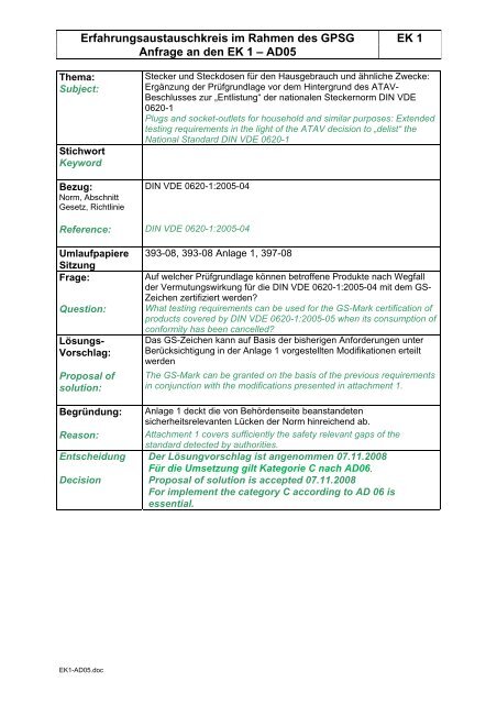
Stecker und Steckdosen für den Hausgebrauch und ähnliche Zwecke:<br />
Ergänzung der Prüfgrundlage vor dem Hintergrund <strong>des</strong> ATAV-<br />
Beschlusses zur „Entlistung“ der nationalen Steckernorm DIN <strong>VDE</strong><br />
0620-1<br />
Plugs and socket-outlets for household and s<strong>im</strong>ilar purposes: Extended<br />
testing requirements in the light of the ATAV decision to „delist“ the<br />
National Standard DIN <strong>VDE</strong> 0620-1<br />
DIN <strong>VDE</strong> 0620-1:2005-04<br />
DIN <strong>VDE</strong> 0620-1:2005-04<br />
393-08, 393-08 Anlage 1, 397-08<br />
Auf welcher Prüfgrundlage können betroffene Produkte nach Wegfall<br />
der Vermutungswirkung für die DIN <strong>VDE</strong> 0620-1:2005-04 mit dem GS-<br />
Zeichen zertifiziert werden?<br />
What testing requirements can be used for the GS-Mark certification of<br />
products covered by DIN <strong>VDE</strong> 0620-1:2005-05 when its consumption of<br />
conformity has been cancelled?<br />
Das GS-Zeichen kann auf Basis der bisherigen Anforderungen unter<br />
Berücksichtigung in der Anlage 1 vorgestellten Modifikationen erteilt<br />
werden<br />
The GS-Mark can be granted on the basis of the previous requirements<br />
in conjunction with the modifications presented in attachment 1.<br />
Anlage 1 deckt die von Behördenseite beanstandeten<br />
sicherheitsrelevanten Lücken der Norm hinreichend ab.<br />
Attachment 1 covers sufficiently the safety relevant gaps of the<br />
standard detected by authorities.<br />
Der Lösungvorschlag ist angenommen 07.11.2008<br />
Für die Umsetzung gilt Kategorie C nach AD06.<br />
Proposal of solution is accepted 07.11.2008<br />
For <strong>im</strong>plement the category C according to AD 06 is<br />
essential.
Anlage 1 zum Dokument <strong>EK</strong>1 393-08<br />
<strong>VDE</strong>-interne Prüfanweisung für Steckvorrichtungen nach<br />
DIN <strong>VDE</strong> 0620-1 (<strong>VDE</strong> 0620-1):2005-04<br />
Ergänzung zu Abschnitt 8.9 Warnhinweise:<br />
d) für ortsveränderliche Steckvorrichtungen:<br />
- Erläuterung der Schutzart (z.B. nur zur Verwendung in trockenen Räumen)<br />
e) für nichtwiederanschließbare Stecker:<br />
- Hinweis, wenn der Stecker nicht für die Verwendung in Verbindung mit<br />
Verlängerungsleitungen usw., geeignet ist (s. Tabelle 20)<br />
Neufassung von Abschnitt 19 Temperaturerhöhung:<br />
Steckvorrichtungen müssen so gebaut sein, dass sie der folgenden Prüfung der<br />
Temperaturerhöhung genügen.<br />
- Steckvorrichtungen mit Leitungen werden geprüft wie angeliefert;<br />
- Wiederanschließbare Steckvorrichtungen ohne Leitung werden mit PVC-isolierten<br />
Leitern ausgestattet, die einen Nennquerschnitt, wie in Tabelle 15 aufgeführt, haben.<br />
Tabelle 15 – Nennquerschnitte von Kupferleitern für die Erwärmungsprüfung<br />
Bemessungsstrom der<br />
Steckvorrichtung<br />
A<br />
Nennquerschnitt mm²<br />
Flexible Leiter bei<br />
bewegbaren<br />
Steckvorrichtungen<br />
16 1,5 2,5<br />
Über 16 4 6<br />
Starre Leiter (ein- oder<br />
mehrdrahtig) für ortsfeste<br />
Steckvorrichtungen<br />
Die Schrauben oder Muttern der Klemmen werden mit zwei Drittel <strong>des</strong> in 12.2.8 festgelegten<br />
Drehmoments angezogen.<br />
Anmerkung 1 Um eine übliche Kühlung der Klemmen sicherzustellen, sollen die<br />
angeschlossenen Leiter eine Länge von min<strong>des</strong>tens 1 m haben.<br />
Unterputz-Steckvorrichtungen werden in Unterputzdosen montiert. Die Dose wird in einen<br />
Hartholzblock eingesetzt, der um die Dose herum mit Gips gefüllt ist, so dass die vordere<br />
Kante der Dose nicht vorsteht und nicht mehr als 5 mm unterhalb der Vorderseite <strong>des</strong><br />
Hartblocks ist.<br />
Anmerkung 2 Die Prüfvorrichtung sollte nach der Herstellung min<strong>des</strong>tens 7 Tage trocknen.<br />
Die Größe <strong>des</strong> Hartholzblockes, der aus mehr als einem Stück gefertigt sein kann, muss so<br />
beschaffen sein, dass der Gips von min<strong>des</strong>tens 25 mm Holz umgeben ist. Der Gips hat eine<br />
Dicke zwischen 10 mm und 15 mm an den größten Abmessungen der Seiten und der Dose.<br />
Anmerkung 3 Die Seiten <strong>des</strong> Hohlraums in dem Hartholzblock dürfen zylinderförmig sein.
Die Leitungen, die an die Steckdose angeschlossen sind, müssen an der Oberseite der Dose<br />
eintreten. Das (Die) Eintrittsloch (-löcher) wird (werden) verschlossen, um Luftzirkulation zu<br />
verhindern. Jeder Leiter in der Dose muss eine Länge von 80 mm ± 10 mm haben.<br />
Aufputz-Steckdosen müssen zentriert an einem Holzblock angebracht werden, der<br />
min<strong>des</strong>tens 20 mm dick, 500 mm breit und 500 mm hoch sein soll.<br />
Andere Steckdosen-Typen müssen nach Anleitung <strong>des</strong> Herstellers montiert werden oder,<br />
falls eine solche Anleitung nicht vorhanden ist, in einer Lage wie für den<br />
best<strong>im</strong>mungsgemäßen Gebrauch, von der angenommen wird, dass sie zu den schwierigsten<br />
Bedingungen führt.<br />
Bei der Prüfung muss die Prüfvorrichtung an einem Ort ohne Luftzug aufgestellt sein.<br />
Steckdosen und Kupplungsdosen werden mit einem Prüfstecker nach Bild 16 geprüft.<br />
Im Falle von Mehrfachsteckdosen wird die Prüfung nur an einer Steckdose von jedem Typ<br />
und jedem Bemessungsstrom durchgeführt. Der Prüfstecker wird in die Steckdose<br />
eingesteckt, die die größte Temperaturerhöhung erwarten läßt. Im Zweifelsfall ist die Prüfung<br />
mit Prüfstecker in einer weiteren Steckdose zu wiederholen.<br />
Stecker werden wie folgt geprüft:<br />
Eine geeignete Prüfvorrichtung wird an jedem aktiven Stift bzw. Schutzkontakt <strong>des</strong> Steckers<br />
zusammen mit einem Thermoelement <strong>im</strong> unteren Teil befestigt<br />
Anmerkung 4 Als geeignete Prüfvorrichtung kann auch eine handelsübliche Steckdose<br />
eingesetzt werden.<br />
Steckvorrichtungen ohne Zusatzfunktion werden 1 h mit einem Wechselstrom nach Tabelle<br />
20 belastet.<br />
Bei Steckvorrichtungen mit drei oder mehr Polen muss der Prüfstrom durch die<br />
Phasenkontakte, wo dies möglich ist, fließen. Zusätzlich müssen weitere Prüfungen<br />
durchgeführt werden, bei denen der Strom durch den Neutralleiter-Kontakt, falls vorhanden,<br />
und den benachbarten Phasenkontakt und durch den Schutzleiter-Kontakt, falls vorhanden,<br />
und den nächstgelegenen Phasenkontakt fließt. Zum Zweck dieser Prüfung werden<br />
Schutzleiter-Kontakte, unabhängig von ihrer Anzahl, als ein Pol betrachtet.<br />
Die Temperatur wird mit Schmelzkörpern, Umschlagfarben oder Thermoelementen ermittelt,<br />
die so ausgewählt und angebracht sind, dass sie vernachlässigbaren Einfluss auf die zu<br />
messende Temperatur haben.<br />
Die Temperaturerhöhung der Klemmen und inneren Verbindungen darf 45 K nicht<br />
überschreiten.<br />
Zusatzfunktionen wie D<strong>im</strong>mer, Sicherungen, Schalter, Energieregler usw., die in<br />
Steckvorrichtungen eingebaut sind, müssen den einschlägigen <strong>VDE</strong>-Best<strong>im</strong>mungen<br />
entsprechen.<br />
Steckvorrichtungen mit Zusatzfunktionen werden wie folgt geprüft:<br />
Die Steckvorrichtungen werden zuerst mit Bemessungsstrom 1 h bzw. bis zum Auslösen<br />
evtl. integrierten Schutzgerätes belastet. Im Fall <strong>des</strong> Auslösens eines integrierten<br />
Schutzgerätes wird die Prüfung mit dem 0,95fachen <strong>des</strong> Auslösestromes <strong>des</strong> Schutzgerätes<br />
wiederholt. Bei Gerätesicherung nach EN 60127-2 wird die Steckvorrichtung mit dem<br />
1,5fachen Sicherungs-Bemessungsstrom 1 h lang bei Sicherungs-Bemessungsstrom bis 6,3<br />
A bzw. 30 min lang bei Sicherungs-Bemessungsstrom über 6,3 A belastet.
Hierbei darf die Temperaturerhöhung an den Klemm- und Verbindungsstellen der<br />
Zusatzfunktionen die in den einschlägigen Vorschriften zulässigen Werte, jedoch nicht mehr<br />
als 70 K, überschreiten. Alle anderen Klemm- und Verbindungsstellen dürfen 45 K nicht<br />
überschreiten.<br />
Anmerkung: Der Bemessungswert der Steckvorrichtung ist der <strong>im</strong> Normblatt festgelegte<br />
Wert.<br />
Danach werden Steckvorrichtungen mit einem Prüfstrom nach Tabelle 20 für 1 h bzw. bis<br />
zum Auslösen eines integrierten Schutzgerätes belastet. Im Fall <strong>des</strong> Auslösens eines<br />
integrierten Schutzgerätes wird die Prüfung mit dem 0,95fachen <strong>des</strong> Auslösestromes <strong>des</strong><br />
Schutzgerätes wiederholt. Bei Gerätesicherung nach EN 60127-2 wird die Steckvorrichtung<br />
mit dem 1,5fachen Sicherungs-Bemessungsstrom 1 h lang bei Sicherungs-<br />
Bemessungsstrom bis 6,3 A bzw. 30 min lang bei Sicherungs-Bemessungsstrom über 6,3 A<br />
belastet.<br />
Diese Prüfung muss nicht wiederholt werden, wenn das Schutzgerät bereits bei Prüfung mit<br />
Bemessungsstrom ausgelöst hat.<br />
Dabei darf die Temperaturerhöhung an den Klemm- und Verbindungsstellen der<br />
Zusatzfunktion für äußere Anschlussleitungen 70 K nicht überschreiten. Für alle anderen<br />
Klemm- und Verbindungsstellen gelten die Temperaturwerte aus den einschlägigen<br />
Best<strong>im</strong>mungen der Zusatzfunktion. Die Temperaturerhöhung an allen anderen Klemm- und<br />
Verbindungsstellen darf 45 K nicht überschreiten.<br />
Ist der Nennquerschnitt der Zuleitung von ortsveränderlichen Steckdosen kleiner als in DIN<br />
<strong>VDE</strong> 0298-300 (<strong>VDE</strong> 0298 Teil 300):2004 (HD 516 S2:1997 + A1:2003) Tabelle 7 für die<br />
Strombelastbarkeit (Bemessungsstrom der Steckdose) angegeben, ist zusätzlich die<br />
Temperatur an der Zuleitung zu messen.<br />
Die Grenztemperaturen, gemessen <strong>im</strong> Abstand von 10 cm von der<br />
Leitungseinführungsstelle, nach DIN <strong>VDE</strong> 0298-300 (<strong>VDE</strong> 0298 Teil 300):2004 Tabellen 4A<br />
bzw. 4B dürfen nicht überschritten werden.<br />
Ergänzung zu Tabelle 20:<br />
Für nichtwiederanschließbare Stecker 16 A 250 V mit Zuleitungen 1,0 mm² und 1,5 mm²,<br />
vorgesehen zur Verwendung an Verlängerungsleitungen, Geräteanschlußleitungen,<br />
ortsveränderlichen Mehrfachsteckdosen, Leitungsrollern sowie Geräten mit eingebauten<br />
Steckdosen nach dieser Norm, die keine geeigneten strombegrenzenden Maßnahmen<br />
enthalten, beträgt für die Prüfung nach Abschnitt 19 der Prüfstrom 20 A.<br />
Für nichtwiederanschließbare Stecker 16 A 250 V mit Zuleitungen 0,5 mm² bzw. 0,75 mm²,<br />
vorgesehen zur Verwendung an Geräteanschlußleitungen, beträgt für die Prüfung nach<br />
Abschnitt 19 der Prüfstrom 3,1 A bzw. 12,5 A.
<strong>VDE</strong>-internal instructions for the testing of plugs and socket-outlets according<br />
to DIN <strong>VDE</strong> 0620-1 (<strong>VDE</strong> 0620-1):2005-04<br />
Supplement to Sub-clause 8.9 safety notices:<br />
d) for portable accessories:<br />
- Explanation of the degree of protection (for example: only for use in dry rooms)<br />
e) for non-rewirable plugs:<br />
- Notice in case of plugs not intended for use in conjunction with extension cord sets etc.<br />
(see Table 20)<br />
New version of clause 19 temperature rise:<br />
Accessories shall be so constructed that they comply with the following temperature-rise test.<br />
- Accessories provided with cords are tested as delivered;<br />
- Rewirable accessories without cords are fitted with polyvinyl chloride insulated<br />
conductors having a nominal cross-sectional area as shown in Table 15.<br />
Table 15 – nominal cross-sectional areas of copper conductors for the temperature-rise test<br />
Rated current of accessory<br />
A Flexible conductors for<br />
portable accessories<br />
16<br />
over 16<br />
1,5<br />
4<br />
Nominal cross-sectional area<br />
mm 2<br />
Rigid conductors (solid or<br />
stranded) for fixed<br />
accessories<br />
The terminal screws or nuts are tightened with a torque equal to two-thirds of that specified in<br />
12.2.8.<br />
NOTE 1: To ensoure normal cooling of the terminals, the conductors connected to them should have a<br />
length of at least 1m.<br />
Flush-mounted accessories are mounted in flush-mounted boxes. The box is based in a<br />
block of pinewood filled around the box with plaster, so that the front edge of the box does<br />
not protrude and is not more than 5 mm below the front surface of the pinewood block.<br />
NOTE 2: The test assembly shoud be allowed to drive for at least seven days when first made.<br />
The size of the pinewood block, wich may be fabricated from more than one piece, shall be<br />
such that there is at least 25 mm of wood surrounding the plaster, the plaster having a<br />
thickness between 10 mm and 15 mm arround the max<strong>im</strong>um d<strong>im</strong>ensions of the si<strong>des</strong> and<br />
rear of the box.<br />
NOTE 3: The si<strong>des</strong> of the cavity in the pinewood block may have a cylindrical shape.<br />
The cables connected to the socket-outlet shall enter through the top of the box, the points of<br />
entry beeing sealed to prevent the circulation of air. The length of each conductor with in the<br />
box shall be 80 mm ± 10 mm.<br />
2,5<br />
6
Surface-type socket-outlets shall be mounted centrally on the surface of a wooden block<br />
which shall be at least 20 mm thick, 500 mm wide and 500 mm high.<br />
Other type of socket-outlets shall be mounted according to the manufacturer’s instruction or,<br />
in the absence of such an instruction, in the possition of normal use considered to give the<br />
most onerous conditions.<br />
The test assembly shall be placed in a draught-free environment for the test.<br />
Socket-outlets and portable socket-outlets are tested using a test plug according to Figure<br />
16. In the case of multiple socket-outlets the test is carried out only on one socket-outlet of<br />
each type and current rating. The test plug is inserted into the socket-outlet in which the<br />
highest temperature rise can be expected. In case of doubt the test is repeated with a test<br />
plug inserted in a further socket-outlet.<br />
Plugs are tested as follows:<br />
An applicable test apparatus is fitted together with a thermocouple on each live pin or the<br />
earthing contact of the plug respectively, if any.<br />
NOTE 4: As an applicable test apparatus a commonly available socket-outlet may be used.<br />
Accessories without additional functions are tested for 1 h with a alternating current as<br />
specified in Table 20.<br />
For accessories having three poles or more, the current during the test shall be passed<br />
through the phase contacts, where applicable. In addition, separate tests shall be made<br />
passing the current through the neutral contact, if any, and the adjacent phase contact and<br />
through the earthing contact, if any, and the nearest phase contact. For the purpose of this<br />
test, earthing contacts, irrespective of their number, are considered as one pole.<br />
The temperature is determined by means of melting particles, colour-changing indicators or<br />
thermocouples, chosen and positioned in such a way that they have negligible effect on the<br />
temperature being determined.<br />
The temperature rise of the terminals and connections shall not exceed 45 K.<br />
Additional functions like d<strong>im</strong>mers, fuses, switches, energy regulators etc. incorporated in<br />
accessories shall comply with the relevant <strong>VDE</strong>-Standards.<br />
Accessories with additional functions are tested as follows:<br />
Accessories are tested with rated current first for 1 h. In case of an integrated protection<br />
device the test is finished if this device trips within 1h.<br />
In case of tripping of the integrated protection device the test will be repeated with 0,95 t<strong>im</strong>es<br />
of the tripping current. In case of cartridge fuse-link according to EN 60127-2 the accessory<br />
are tested with 1,5 t<strong>im</strong>es of the rated current of the fuse-link. The testing t<strong>im</strong>e is 1 h for fuselinks<br />
with a rated current up to 6.3 A or 30 min for fuse-links with a rated current exceeding<br />
6.3 A.<br />
The temperature rise of the terminals and connections of the additional functions shall not<br />
exceed the values given in the relevant standards for the additional functions, but not more<br />
than 70 K. The temperature rise of all other terminals and connections shall not exceed 45 K.<br />
NOTE: The nominal value of the accessory is the value given in the relevant Standard Sheet.
After that the accessories are tested for 1 h with a alternating current as specified in table 20<br />
for 1 h.<br />
In case of an integrated protection device, the test is finished if this device trips within 1 h.<br />
In case of tripping of the integrated protection device the test will be repeated with 0,95 t<strong>im</strong>es<br />
of the tripping current. In case of cartridge fuse-link according to EN 60127-2 the accessory<br />
is tested with 1,5 t<strong>im</strong>es of the rated current of the fuse-link. The testing t<strong>im</strong>e is 1 h for fuselinks<br />
with a rated current up to 6.3 A or 30 min for fuse-links with a rated current exceeding<br />
6.3 A.<br />
It is not necessary to repeat this test if the protective device has already operated during the<br />
test with rated current.<br />
The temperature rise of the terminals and connections of the additional functions for<br />
incomming cords shall not exceed 70K. For all other terminals and connections of the<br />
additional functions the values given in the relevant standards for the additional functions are<br />
valid. The temperature rise of all other terminals and connections shall not exceed 45 K.<br />
If the cross-sectional area of the cord of portable socket-outlets is less than the value stated<br />
in DIN <strong>VDE</strong> 0298-300 (<strong>VDE</strong> 0298 Teil 300):2004 (HD 516 S2:1997 + A1:2003) Table 7 for<br />
the current carrying capacity (rated current of the socket-outlet) the temperature of the cord<br />
shall be measured additionally in a distance of 10 cm from the cord entry. The temperature<br />
l<strong>im</strong>its specified in Table 4A or 4B according to DIN <strong>VDE</strong> 0298-300 (<strong>VDE</strong> 0298 Teil 300):2004<br />
shall not be exceeded.<br />
Supplement to Table 20:<br />
For non rewirable plugs with rating 16 A 250 V provided with cords of cross-sectional area of<br />
1,0 mm² und 1,5 mm², forseen for use on cord extension sets, cord sets, portable socketoutlets,<br />
cable reels as well as appliances with incorporated socket-outlets according to this<br />
standard, having no suitable current l<strong>im</strong>iting device, the test current is 20 A for the test<br />
according to clause 19.<br />
For non-rewirable plugs with rating 16 A 250 V provided with cords of cross-sectional area<br />
0.5 mm² or 0.75 mm² respectively, foreseen for use on cord sets, the test current is 3.1 A or<br />
12.5 A respectively for the test according to clause 19.