the beneficial coupling of cardioid low frequency sources to ... - W Vier
the beneficial coupling of cardioid low frequency sources to ... - W Vier
the beneficial coupling of cardioid low frequency sources to ... - W Vier

You also want an ePaper? Increase the reach of your titles
YUMPU automatically turns print PDFs into web optimized ePapers that Google loves.
Proceedings <strong>of</strong> <strong>the</strong> Institute <strong>of</strong> Acoustics<br />
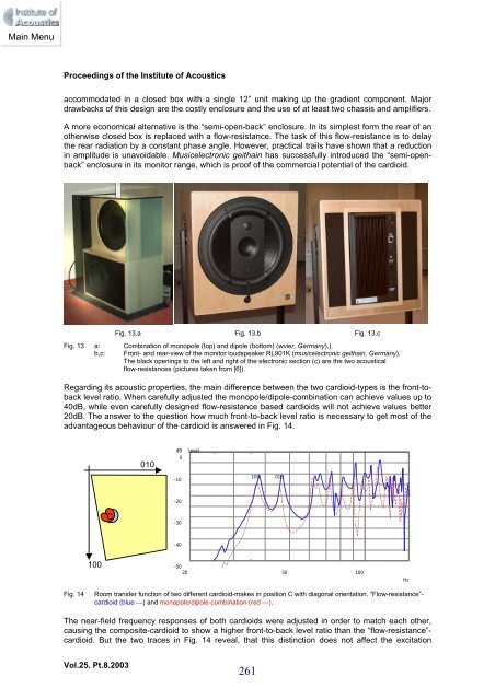
accommodated in a closed box with a single 12” unit making up <strong>the</strong> gradient component. Major<br />
drawbacks <strong>of</strong> this design are <strong>the</strong> costly enclosure and <strong>the</strong> use <strong>of</strong> at least two chassis and amplifiers.<br />
A more economical alternative is <strong>the</strong> “semi-open-back” enclosure. In its simplest form <strong>the</strong> rear <strong>of</strong> an<br />
o<strong>the</strong>rwise closed box is replaced with a f<strong>low</strong>-resistance. The task <strong>of</strong> this f<strong>low</strong>-resistance is <strong>to</strong> delay<br />
<strong>the</strong> rear radiation by a constant phase angle. However, practical trails have shown that a reduction<br />
in amplitude is unavoidable. Musicelectronic geithain has successfully introduced <strong>the</strong> “semi-openback”<br />
enclosure in its moni<strong>to</strong>r range, which is pro<strong>of</strong> <strong>of</strong> <strong>the</strong> commercial potential <strong>of</strong> <strong>the</strong> <strong>cardioid</strong>.<br />
Vol.25. Pt.8.2003<br />
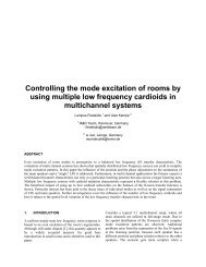
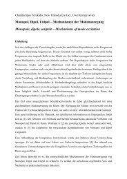
Fig. 13.a Fig. 13.b Fig. 13.c<br />
Fig. 13 a: Combination <strong>of</strong> monopole (<strong>to</strong>p) and dipole (bot<strong>to</strong>m) (wvier, Germany).).<br />
b,c: Front- and rear-view <strong>of</strong> <strong>the</strong> moni<strong>to</strong>r loudspeaker RL901K (musicelectronic geithain, Germany).<br />
The black openings <strong>to</strong> <strong>the</strong> left and right <strong>of</strong> <strong>the</strong> electronic section (c) are <strong>the</strong> two acoustical<br />
f<strong>low</strong>-resistances (pictures taken from [6]).<br />
Regarding its acoustic properties, <strong>the</strong> main difference between <strong>the</strong> two <strong>cardioid</strong>-types is <strong>the</strong> front-<strong>to</strong>back<br />
level ratio. When carefully adjusted <strong>the</strong> monopole/dipole-combination can achieve values up <strong>to</strong><br />
40dB, while even carefully designed f<strong>low</strong>-resistance based <strong>cardioid</strong>s will not achieve values better<br />
20dB. The answer <strong>to</strong> <strong>the</strong> question how much front-<strong>to</strong>-back level ratio is necessary <strong>to</strong> get most <strong>of</strong> <strong>the</strong><br />
advantageous behaviour <strong>of</strong> <strong>the</strong> <strong>cardioid</strong> is answered in Fig. 14.<br />
100<br />
C<br />
010<br />
dB<br />
0<br />
-10<br />
-20<br />
-30<br />
-40<br />
Level<br />
100 010<br />
-50<br />
20 50 100<br />
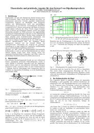
Fig. 14 Room transfer function <strong>of</strong> two different <strong>cardioid</strong>-makes in position C with diagonal orientation. “F<strong>low</strong>-resistance”<strong>cardioid</strong><br />
(blue ⎯) and monopole/dipole-combination (red ---).<br />
The near-field <strong>frequency</strong> responses <strong>of</strong> both <strong>cardioid</strong>s were adjusted in order <strong>to</strong> match each o<strong>the</strong>r,<br />
causing <strong>the</strong> composite-<strong>cardioid</strong> <strong>to</strong> show a higher front-<strong>to</strong>-back level ratio than <strong>the</strong> “f<strong>low</strong>-resistance”<strong>cardioid</strong>.<br />
But <strong>the</strong> two traces in Fig. 14 reveal, that this distinction does not affect <strong>the</strong> excitation<br />
Hz
![Uwe KEMPE / Charalampos FEREKIDIS [w vier] Praktische ...](https://img.yumpu.com/16428023/1/184x260/uwe-kempe-charalampos-ferekidis-w-vier-praktische-.jpg?quality=85)