Demonstration of an Aerodynamic Design Process for ...
Demonstration of an Aerodynamic Design Process for ...
Demonstration of an Aerodynamic Design Process for ...

You also want an ePaper? Increase the reach of your titles
YUMPU automatically turns print PDFs into web optimized ePapers that Google loves.
OPENFOAM<br />
For two- <strong>an</strong>d three-dimensional flow simulations the CFD<br />
toolbox OpenFOAM [18] is used. OpenFOAM consists <strong>of</strong> several<br />
libraries to model steady, unsteady, compressible, incompressible,<br />
laminar <strong>an</strong>d turbulent RANS as well as LES <strong>an</strong>d other<br />
flow physics. The main adv<strong>an</strong>tage is that different libraries c<strong>an</strong><br />
be combined in the top-level solvers in order to simulate multiphysics<br />
flow.<br />
Flat Cascade Pr<strong>of</strong>ile<br />
Flat two-dimensional cascade pr<strong>of</strong>iles are simulated with the<br />
st<strong>an</strong>dard sonicFoam solver <strong>of</strong> OpenFOAM-1.6. SonicFoam<br />
is a tr<strong>an</strong>sient solver <strong>for</strong> sub- <strong>an</strong>d supersonic, laminar or turbulent<br />
flows, including RANS <strong>an</strong>d LES models. The rotor me<strong>an</strong> line<br />
pr<strong>of</strong>ile <strong>of</strong> the axial compressor is computed with this solver <strong>an</strong>d<br />
the k-Omega SST turbulence model is used. A const<strong>an</strong>t stagnation<br />
temperature, stagnation pressure <strong>an</strong>d the direction <strong>of</strong> the<br />
velocity are assumed as boundary conditions at the inlet. A const<strong>an</strong>t<br />
static pressure is applied at the outlet. Periodic boundary<br />
conditions <strong>for</strong> the upper <strong>an</strong>d lower sides, cf. Fig. 5, <strong>an</strong>d special<br />
empty boundary conditions <strong>for</strong> two-dimensional problems<br />
are used at “hub” <strong>an</strong>d “shroud”.<br />
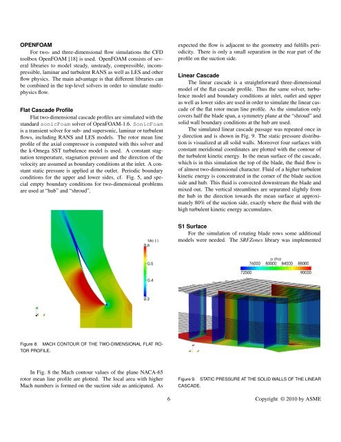
Figure 8. MACH CONTOUR OF THE TWO-DIMENSIONAL FLAT RO-<br />
TOR PROFILE.<br />
In Fig. 8 the Mach contour values <strong>of</strong> the pl<strong>an</strong>e NACA-65<br />
rotor me<strong>an</strong> line pr<strong>of</strong>ile are plotted. The local area with higher<br />
Mach numbers is <strong>for</strong>med on the suction side as <strong>an</strong>ticipated. As<br />
expected the flow is adjacent to the geometry <strong>an</strong>d fulfills periodicity.<br />
There is only a small separation in the rear part <strong>of</strong> the<br />
pr<strong>of</strong>ile on the suction side.<br />
Linear Cascade<br />
The linear cascade is a straight<strong>for</strong>ward three-dimensional<br />
model <strong>of</strong> the flat cascade pr<strong>of</strong>ile. Thus the same solver, turbulence<br />
model <strong>an</strong>d boundary conditions at inlet, outlet <strong>an</strong>d upper<br />
as well as lower sides are used in order to simulate the linear cascade<br />
<strong>of</strong> the flat rotor me<strong>an</strong> line pr<strong>of</strong>ile. As the simulation only<br />
covers half the blade sp<strong>an</strong>, a symmetry pl<strong>an</strong>e at the “shroud” <strong>an</strong>d<br />
solid wall boundary conditions at the hub are used.<br />
The simulated linear cascade passage was repeated once in<br />
y direction <strong>an</strong>d is shown in Fig. 9. The static pressure distribution<br />
is visualized at all solid walls. Moreover four surfaces with<br />
const<strong>an</strong>t meridional coordinates are plotted with the contour <strong>of</strong><br />
the turbulent kinetic energy. In the me<strong>an</strong> surface <strong>of</strong> the cascade,<br />
which is in this simulation the top <strong>of</strong> the blade, the fluid flow is<br />
<strong>of</strong> almost two-dimensional character. Fluid <strong>of</strong> a higher turbulent<br />
kinetic energy is concentrated in the corner <strong>of</strong> the blade suction<br />
side <strong>an</strong>d hub. This fluid is convected downstream the blade <strong>an</strong>d<br />
mixed out. The vertical streamlines are separated slightly from<br />
the hub in the direction towards the me<strong>an</strong> surface at approximately<br />
80% <strong>of</strong> the suction side, exactly where the fluid with the<br />
high turbulent kinetic energy accumulates.<br />
S1 Surface<br />
For the simulation <strong>of</strong> rotating blade rows some additional<br />
models were needed. The SRFZones library was implemented<br />
Figure 9. STATIC PRESSURE AT THE SOLID WALLS OF THE LINEAR<br />
CASCADE.<br />
6 Copyright © 2010 by ASME

![04. The Da Vinci Code - Dan Brown(2003)[dobd.tk].pdf](https://img.yumpu.com/17290229/1/190x245/04-the-da-vinci-code-dan-brown2003dobdtkpdf.jpg?quality=85)