Typ 670.pdf - Andreas Hofer Hochdrucktechnik GmbH
Typ 670.pdf - Andreas Hofer Hochdrucktechnik GmbH
Typ 670.pdf - Andreas Hofer Hochdrucktechnik GmbH

You also want an ePaper? Increase the reach of your titles
YUMPU automatically turns print PDFs into web optimized ePapers that Google loves.
Bestellinformationen /<br />
Ordering Information<br />
Beispiel / Example 670<br />
Anlüftvorrichtung / Lifting Device<br />
Einstellbereich / Set Pressure Range<br />
Anschluss Eintritt / Connection Bestellinformationen<br />
Ordering<br />
Inlet<br />
Information<br />
Anschluss Austritt / Connection Outlet<br />
Werkstoff Austritt / Material Outlet<br />
Kegeldichtung / Cone Seal<br />
Anlüftvorrichtung /<br />
Lifting Device<br />
mit / with<br />
ohne / without<br />
Einstellbereich /<br />
Set Pressure Range<br />
100 - 115 bar<br />
115 - 180 bar<br />
180 - 285 bar<br />
285 - 365 bar<br />
365 - 455 bar<br />
455 - 570 bar<br />
570 - 720 bar<br />
720 - 910 bar<br />
910 -1100 bar<br />
A<br />
–<br />
07<br />
08<br />
09<br />
10<br />
11<br />
12<br />
13<br />
14<br />
15<br />
technische Änderungen vorbehalten / technical modifications reserved<br />
SV <strong>Typ</strong>/type 670 2/2 © by <strong>Andreas</strong> <strong>Hofer</strong> <strong>GmbH</strong> 06.01<br />
Anschluss Eintritt / Connection Inlet<br />
Außengewinde G 1/2 A technische Gase<br />
Innengewinde 3/8"-18 NPT<br />
HOFER Zapfen G 1/2 A<br />
Innengewinde G 1/2 für HOFER Zapfen<br />
HOFER Block G 1/2 für Rohr 10 x 2<br />
HOFER Block G 7/8 für Rohr 14 x 2,5<br />
Anschluss Austritt / Connection Outlet<br />
Werkstoff Austritt / Material Outlet<br />
Kegeldichtung / Cone Seal<br />
A . 08 . 303 . 51 .<br />
male thread G 1/2 A technical gases<br />
female thread 3/8" -18 NPT<br />
HOFER pivot G 1/2 A<br />
female thread G 1/2 for HOFER pivot<br />
HOFER block G1/2 for tube 10 x 2<br />
HOFER block G 7/8 for tube 14 x 2,5<br />
Rohrverschraubung DL18 DIN 2353 tube fitting DL18 DIN 2353 PN 160 51<br />
Stahl<br />
Edelstahl 1.4571<br />
Hinweis<br />
Zusätzlich zu den aufgeführten Standardlösungen bieten wir<br />
Ihnen auch systembezogene Ventil- und Anschlussausführungen<br />
(z.B. EO, Dilo, Swagelok, A-Lok, Hoke, IG-Norm,<br />
Flansche, usw.) an. Bitte setzen Sie sich mit uns in Verbindung.<br />
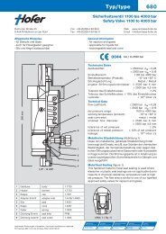
Durchflussdiagramm / Flow Chart<br />
Nm3 / h Gase / gases<br />
kg / h Wasser / water<br />
30000<br />
27000<br />
24000<br />
21000<br />
18000<br />
15000<br />
12000<br />
9000<br />
6000<br />
3000<br />
0<br />
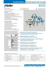
Technische Hinweise<br />
Normal-Sicherheitsventile erreichen nach dem Ansprechen<br />
innerhalb eines Druckanstieges von max. 10% den für den<br />
abzuführenden Massenstrom notwendigen Hub.<br />
Für eine sichere Funktion muss die gesamte Systemauslegung<br />
berücksichtigt werden. Die richtige Auswahl der Komponenten,<br />
ihrer Materialien, ihrer Temperatur- und Druckraten<br />
sowie vorschriftsmäßige Montage und Inbetriebnahme obliegt<br />
der Verantwortung des Anwenders und Anlagenplaners.<br />
.<br />
<strong>Typ</strong>/type 670<br />
carbon steel<br />
stainless steel 1.4571<br />
Metall metal 0<br />
2<br />
0<br />
186<br />
275<br />
303<br />
313<br />
334<br />
339<br />
Remarks<br />
In addition to the shown standard versions we also offer various<br />
customized solutions for our valves and end connections (e.g.<br />
EO, Dilo, Swagelok, A-Lok, Hoke, IG-standard, flanges, etc.).<br />
Please don`t hesitate to ask for further information.<br />
Abblasemenge / Öffnungsdruck<br />
Blow-off Quantity / Set Pressure<br />
0 200 400 600<br />
bar<br />
800 1000 1200<br />
H 2 O<br />
Technical Information<br />
After responding within a maximum overpressure of 10 %,<br />
these safety valves achieve the stroke required for the mass<br />
flow to be discharged.<br />
The total system design must be considered to ensure safe<br />
performance. Component function, material compabilities,<br />
adequate ratings, proper installation, operation and maintenance<br />
are the responsibilities of the system user and designer.<br />
H 2<br />
He<br />
N 2 / Ar<br />
PN 400<br />
PN 500<br />
PN 1100<br />
PN 1100<br />
PN 1100<br />
PN 1100<br />
-40 ... +120° C<br />
-60 ... +200° C<br />
1<br />
2