

Inverted Shunt Regulator - Tube CAD Journal
Inverted Shunt Regulator - Tube CAD Journal
Inverted Shunt Regulator - Tube CAD Journal

Create successful ePaper yourself
Turn your PDF publications into a flip-book with our unique Google optimized e-Paper software.
January 2001 ^^ TUBE <strong>CAD</strong> JOURNAL ^^<br />
Volume 3 Number 1 >><br />
From this viewpoint, the ground is the signal<br />
and any deviation from that signal at the output<br />
is countered by the feedback until it is<br />
eliminated.<br />
So which is better? Better for what? Better for<br />
needlessly heating the room? Better for using a<br />
battery power supply? Better for isolating<br />
delicate signal currents in an amplifier? Each<br />
finds its own place in tube audio designer's<br />
palette. My preference is to use kind for kind: a<br />
shunt regulator for steady average current draw<br />
circuits, for example Class A amplifier stages,<br />
and a series regulator for variable current draw<br />
circuits, for example Class AB, B output stages.<br />
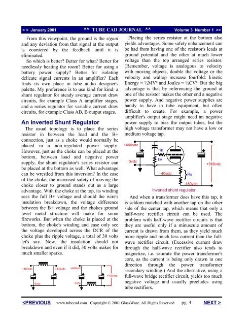
An <strong>Inverted</strong> <strong>Shunt</strong> <strong>Regulator</strong><br />
The usual topology is to place the series<br />
resistor in between the load and the B+<br />
connection, just as a choke would normally be<br />
placed in a non-regulated power supply.<br />
However, just as the choke can be placed at the<br />
bottom, between load and negative power<br />
supply, the shunt regulator's series resistor can<br />
be placed at the bottom as well. What advantage<br />
can be wrestled from this inversion? In the case<br />
of the choke, the increased safety of moving the<br />
choke closer to ground stands out as a large<br />
advantage. With the choke at the top, its winding<br />
sees the full B+ voltage and should the wire's<br />
insulation breakdown, the voltage difference<br />
between the B+ voltage and the chokes ground<br />
level metal structure will make for some<br />
fireworks. But when the choke is placed at the<br />
bottom, the choke's winding and case only see<br />
the voltage developed across the DCR of the<br />
choke plus the ripple voltage, a total of 30 volts<br />
let's say. Now, the insulation should not<br />
breakdown and even if it did, 30 volts makes for<br />
much smaller sparks.<br />
+400vdc<br />
0vdc<br />


