®Hydrovex® VHV / SVHV Vertical Vortex Flow Regulator
®Hydrovex® VHV / SVHV Vertical Vortex Flow Regulator
®Hydrovex® VHV / SVHV Vertical Vortex Flow Regulator

Create successful ePaper yourself
Turn your PDF publications into a flip-book with our unique Google optimized e-Paper software.
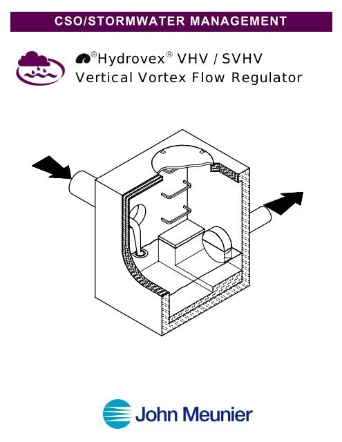
CSO/STORMWATER MANAGEMENT<br />
® Hydrovex ® <strong>VHV</strong> / S<strong>VHV</strong><br />
<strong>Vertical</strong> <strong>Vortex</strong> <strong>Flow</strong> <strong>Regulator</strong>
HYDROVEX ® <strong>VHV</strong> / S<strong>VHV</strong> VERTICAL VORTEX FLOW REGULATOR<br />
INTRODUCTION<br />
One of the major problems of urban wet weather flow management is the runoff generated after a heavy rainfall. During a storm,<br />
uncontrolled flows may overload the drainage system and cause flooding. Due to increased velocities, sewer pipe wear is increased<br />
dramatically and results in network deterioration. In a combined sewer system, the wastewater treatment plant may also experience<br />
significant increases in flows during storms, thereby losing its treatment efficiency.<br />
A simple means of controlling excessive water runoff is by controlling excessive flows at their origin (manholes). John Meunier<br />
Inc. manufactures the HYDROVEX ® <strong>VHV</strong> / S<strong>VHV</strong> line of vortex flow regulators to control stormwater flows in sewer networks,<br />
as well as manholes.<br />
The vortex flow regulator design is based on the fluid mechanics principle of the forced vortex. This grants flow regulation without<br />
any moving parts, thus reducing maintenance. The operation of the regulator, depending on the upstream head and discharge,<br />
switches between orifice flow (gravity flow) and vortex flow. Although the concept is quite simple, over 12 years of research have<br />
been carried out in order to get a high performance.<br />
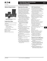
The HYDROVEX ® <strong>VHV</strong> <strong>Vertical</strong> <strong>Vortex</strong> <strong>Flow</strong> <strong>Regulator</strong> (refer to Figure 1) is manufactured entirely of stainless steel, and<br />
consists of a hollow body (1) (in which flow control takes place) and an outlet orifice (7). Two rubber "O" rings (3) seal and retain<br />
the unit inside the outlet pipe. Two stainless steel retaining rings (4) are welded on the outlet sleeve to ensure that there is no<br />
shifting of the "O" rings during installation and use.<br />
1. BODY<br />
2. SLEEVE<br />
3. O-RING<br />
4. RETAINING RINGS<br />
(SQUARE BAR)<br />
5. ANCHOR PLATE<br />
6. INLET<br />
7. OUTLET ORIFICE<br />
HYDROVEX ® <strong>VHV</strong> VERTICAL VORTREX FLOW REGULATOR<br />
FIGURE 1 - <strong>VHV</strong><br />
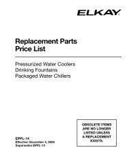
HYDROVEX ® S<strong>VHV</strong> SPECIAL VERTICAL VORTEX FLOW REGULATOR<br />
FIGURE 1 – S<strong>VHV</strong><br />
1. BODY<br />
2. SLEEVE<br />
3. O-RING<br />
4. RETAINING RINGS<br />
(SQUARE BAR)<br />
5. ANCHOR PLATE<br />
6. INLET<br />
7. OUTLET ORIFICE
ADVANTAGES OF THE HYDROVEX ® FLOW REGULATORS<br />
• The HYDROVEX ® <strong>VHV</strong> / S<strong>VHV</strong> line of flow regulators is manufactured entirely of stainless steel,<br />
making them durable and corrosion resistant.<br />
• Having no moving parts, they require minimal maintenance.<br />
• The geometry of the HYDROVEX ® <strong>VHV</strong> / S<strong>VHV</strong> flow regulators allows a control equal to an orifice<br />
plate, having a cross section area 4 to 6 times smaller. This decreases the chance of blockage of the<br />
regulator, due to sediments and debris found in stormwater flows.<br />
• Installation of the HYDROVEX ® <strong>VHV</strong> / S<strong>VHV</strong> flow regulators is quick and straightforward and is<br />
performed after all civil works are completed.<br />
• Installation requires no special tools or equipment and may be carried out by any contractor.<br />
• Installation may be carried out in existing structures.<br />
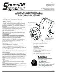
HYDROVEX SELECTION CRITERIA <strong>VHV</strong> OR S<strong>VHV</strong><br />
Figure 2 is a graphical representation of the head vs. discharge range for various <strong>VHV</strong> or S<strong>VHV</strong> regulators. This curve is a<br />
function of the maximum upstream static water pressure (head) and the discharge. As may be seen from the two curves, the S<strong>VHV</strong><br />
models have larger cross-sectional flow areas than the <strong>VHV</strong>'s for a given discharge and head.<br />
Model selection is performed by determining the maximum design flow at the manhole outlet and the maximum design head at the<br />
insert of the manhole outlet pipe. Each regulator is applicable for operation within a range of head and discharge values, as<br />
illustrated by the graph. Using this information one can refer to Figure 2 and determine which model is applicable. All selections<br />
should be verified by John Meunier Inc. personnel prior to fabrication<br />
FIGURE 3: DISCHARGE CURVE FOR A HYDROVEX ® 100 S<strong>VHV</strong>-1-100<br />
AND A 4" Ø ORIFICE PLATE
<strong>VHV</strong> <strong>Vertical</strong> <strong>Vortex</strong> <strong>Flow</strong> <strong>Regulator</strong><br />
FIGURE 2 - <strong>VHV</strong>
S<strong>VHV</strong> <strong>Vertical</strong> <strong>Vortex</strong> <strong>Flow</strong> <strong>Regulator</strong><br />
FIGURE 2 - S<strong>VHV</strong>
DIMENSIONING OF MANHOLES<br />
Most HYDROVEX ® models may be installed in a standard 36-inch diameter manhole. All models may also be installed in a<br />
rectangular manhole with a minimum dimension of 36 inches (24 inch diameter or rectangular manhole may be used for smaller<br />
models).<br />
NOTE that in the case of a square manhole, the outlet flow pipe must be centered on the wall to ensure enough clearance for the<br />
unit. A minimum clearance "H" should be established between the floor of the manhole and the invert of the outlet pipe to install the<br />
regulator. Figure 4 gives the various dimensions required for a given regulator.<br />
HOW TO SPECIFY THE TYPE OF HYDROVEX ® REGULATOR<br />
In order to specify a HYDROVEX ® regulator, the following parameters must be defined:<br />
• The model number (ex: 100-<strong>VHV</strong>-1)<br />
• The diameter and type of outlet pipe (ex: 6" diam. SDR 35 or 8" diam. RCP)<br />
• The desired discharge (ex: 50 l/s or 1.76 CFS)<br />
• The upstream head (ex: 2 m or 6.56 ft.) *<br />
• The manhole diameter (ex: 36" diam.)<br />
• The minimum clearance "H" (ex: 10 inches)<br />
• The material type (ex: 304 s/s, 11 Ga. standard)<br />
PLEASE NOTE THAT WHEN REQUESTING A PROPOSAL, WE SIMPLY REQUIRE THAT YOU PROVIDE US WITH<br />
THE FOLLOWING:<br />
project design flow rate<br />
pressure head<br />
chamber’s outlet pipe diameter<br />
NOTE: Upstream head is defined as the difference in elevation between the maximum upstream water level and the<br />
invert of the outlet pipe where the HYDROVEX ® flow regulator is to be installed.<br />
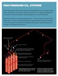
Typical <strong>VHV</strong> in factory<br />
<strong>VHV</strong> with air vent for minimal slopes
FLOW REGULATOR TYPICAL INSTALLATION IN CIRCULAR MANHOLE<br />
FIGURE 4 ( MODEL <strong>VHV</strong> )<br />
Model<br />
Number<br />
<strong>Regulator</strong><br />
Diameter<br />
A (mm)<br />
Manhole<br />
Diameter<br />
B (mm)<br />
Minimum<br />
Outlet Pipe<br />
C (mm)<br />
Minimum<br />
Clearance<br />
H (mm)<br />
50<strong>VHV</strong>-1 203 600 150 127<br />
75<strong>VHV</strong>-1 280 600 150 152<br />
100<strong>VHV</strong>-1 356 900 150 203<br />
125<strong>VHV</strong>-2 330 900 200 203<br />
150<strong>VHV</strong>-2 406 900 200 229<br />
200<strong>VHV</strong>-2 533 1200 254 305<br />
250<strong>VHV</strong>-2 660 1200 300 356<br />
300<strong>VHV</strong>-2 787 1600 375 406<br />
350<strong>VHV</strong>-2 914 1800 375 508<br />
Minimum clearance “H” relates to the diameter indicated in the chart.<br />
If the outlet diameter decreases, the “H” clearance will also decrease.
FLOW REGULATOR TYPICAL INSTALLATION IN CIRCULAR MANHOLE<br />
FIGURE 4 ( MODEL S<strong>VHV</strong> )<br />
Model<br />
Number<br />
<strong>Regulator</strong><br />
Diameter<br />
A (mm)<br />
Manhole<br />
Diameter<br />
B (mm)<br />
Minimum<br />
Outlet Pipe<br />
C (mm)<br />
Minimum<br />
Clearance<br />
H (mm)<br />
25 S<strong>VHV</strong>-1 152 600 150 152<br />
32 S<strong>VHV</strong>-1 178 600 150 152<br />
40 S<strong>VHV</strong>-1 229 600 150 152<br />
50 S<strong>VHV</strong>-1 279 600 150 152<br />
75 S<strong>VHV</strong>-1 432 900 150 279<br />
100 S<strong>VHV</strong>-2 356 900 200 254<br />
125 S<strong>VHV</strong>-2 432 900 200 305<br />
150 S<strong>VHV</strong>-2 559 1200 250 356<br />
200 S<strong>VHV</strong>-2 686 1600 300 457<br />
250 S<strong>VHV</strong>-2 864 1800 375 559<br />
300 S<strong>VHV</strong>-2 1041 2400 375 660<br />
350 S<strong>VHV</strong>-2 1194 2400 375 711<br />
Minimum clearance “H” relates to the diameter indicated in the chart. If the outlet<br />
diameter decreases, the “H” clearance will also decrease
FLOW REGULATOR TYPICAL INSTALLATION IN SQUARE MANHOLE<br />
FIGURE 4 ( MODEL <strong>VHV</strong> )<br />
Model<br />
Number<br />
<strong>Regulator</strong><br />
Diameter<br />
A (mm)<br />
Manhole<br />
Min. width<br />
B (mm)<br />
Minimum<br />
Outlet Pipe<br />
C (mm<br />
Minimum<br />
Clearance<br />
H (mm)<br />
50<strong>VHV</strong>-1 203 600 150 127<br />
75<strong>VHV</strong>-1 280 600 150 152<br />
100<strong>VHV</strong>-1 356 600 150 203<br />
125<strong>VHV</strong>-2 330 600 200 203<br />
150<strong>VHV</strong>-2 406 600 200 229<br />
200<strong>VHV</strong>-2 533 900 254 305<br />
250<strong>VHV</strong>-2 660 900 300 356<br />
300<strong>VHV</strong>-2 787 1200 375 406<br />
350<strong>VHV</strong>-2 914 1200 375 508<br />
Minimum clearance “H” relates to the diameter indicated in the chart.<br />
If the outlet diameter decreases, the “H” clearance will also decrease.
FLOW REGULATOR TYPICAL INSTALLATION IN SQUARE MANHOLE<br />
FIGURE 4 ( MODEL S<strong>VHV</strong> )<br />
Model<br />
Number<br />
<strong>Regulator</strong><br />
Diameter<br />
A (mm)<br />
Manhole<br />
Min. width<br />
B (mm)<br />
Minimum<br />
Outlet Pipe<br />
C (mm)<br />
Minimum<br />
Clearance<br />
H (mm)<br />
25 S<strong>VHV</strong>-1 152 600 150 152<br />
32 S<strong>VHV</strong>-1 178 600 150 229<br />
40 S<strong>VHV</strong>-1 229 600 150 229<br />
50 S<strong>VHV</strong>-1 279 600 150 152<br />
75 S<strong>VHV</strong>-1 432 600 150 229<br />
100 S<strong>VHV</strong>-2 356 600 200 178<br />
125 S<strong>VHV</strong>-2 432 600 200 229<br />
150 S<strong>VHV</strong>-2 559 600 250 254<br />
200 S<strong>VHV</strong>-2 686 900 300 330<br />
250 S<strong>VHV</strong>-2 864 900 375 406<br />
300 S<strong>VHV</strong>-2 1041 1200 375 508<br />
350 S<strong>VHV</strong>-2 1194 1200 375 610<br />
Minimum clearance “H” relates to the diameter indicated in the chart.<br />
If the outlet diameter decreases, the “H” clearance will also decrease.
<strong>VHV</strong>-1-O (typical model with<br />
odor control inlet)<br />
Typical chamber for <strong>VHV</strong>-S<strong>VHV</strong> with Gooseneck<br />
FV – S<strong>VHV</strong> (mounted on<br />
sliding plate)<br />
FV - <strong>VHV</strong> (mounted on sliding plate<br />
with odor control inlet)<br />
<strong>VHV</strong> with Gooseneck assembly in existing chamber without<br />
minimum release at the bottom
INSTALLATION<br />
Typical roof drain chamber<br />
<strong>VHV</strong> used as roof drain in building’s piping<br />
The installation of a HYDROVEX ® regulator may be undertaken once the manhole and piping is in place. Installation consists of<br />
simply fitting the regulator into the outlet pipe of the manhole. John Meunier Inc. recommends the use of a lubricant on the outlet<br />
pipe, in order to facilitate the insertion and orientation of the flow controller.<br />
MAINTENANCE<br />
HYDROVEX ® regulators are manufactured in such a way as to be maintenance free; however, a periodic inspection (every 3-6<br />
months) is suggested in order to ensure that neither the inlet nor the outlet has become blocked with debris. The manhole should<br />
undergo periodically, particularly after major storms, inspection and cleaning as established by the municipality<br />
GUARANTEE<br />
The HYDROVEX ® line of regulators are guaranteed against both design and manufacturing defects for a period of 5 years. Should a<br />
unit be defective, John Meunier Inc. is solely responsible for either modification or replacement of the unit, at their discretion.<br />
Head Office<br />
4105 Sartelon<br />
St-Laurent (Quebec) Canada H4S 2B3<br />
Tel. : 514-334-7230 www.johnmeunier.com<br />
Fax : 514-334-5070 cso@johnmeunier.com<br />
Ontario Office<br />
2000 Argentia Road, Plaza 4, Unit 430<br />
Mississauga (Ontario) Canada L5N 1W1<br />
Tel. : 905-286-4846 www.johnmeunier.com<br />
Fax : 905-286-0488 ontario@johnmeunier.com<br />
Revised: 2006-07-25