FEMA P55 Coastal Construction Manual, Fourth Edition - Mad Cad
FEMA P55 Coastal Construction Manual, Fourth Edition - Mad Cad
FEMA P55 Coastal Construction Manual, Fourth Edition - Mad Cad

Create successful ePaper yourself
Turn your PDF publications into a flip-book with our unique Google optimized e-Paper software.
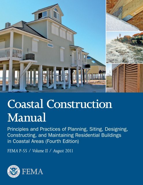
<strong>Coastal</strong> <strong>Construction</strong><br />
<strong>Manual</strong><br />
Principles and Practices of Planning, Siting, Designing,<br />
Constructing, and Maintaining Residential Buildings<br />
in <strong>Coastal</strong> Areas (<strong>Fourth</strong> <strong>Edition</strong>)<br />
<strong>FEMA</strong> P-55 / Volume II / August 2011
<strong>Coastal</strong> <strong>Construction</strong><br />
<strong>Manual</strong><br />
Principles and Practices of Planning, Siting,<br />
Designing, Constructing, and Maintaining<br />
Residential Buildings in <strong>Coastal</strong> Areas<br />
(<strong>Fourth</strong> <strong>Edition</strong>)<br />
<strong>FEMA</strong> P-55 / Volume II / August 2011
All illustrations in this document were created by<br />
<strong>FEMA</strong> or a <strong>FEMA</strong> contractor unless otherwise noted.<br />
All photographs in this document are public domain or taken<br />
by <strong>FEMA</strong> or a <strong>FEMA</strong> contractor, unless otherwise noted.
1 CHAPTER TITLE<br />
Preface<br />
COASTAL CONSTRUCTION MANUAL<br />
The 2011 <strong>Coastal</strong> <strong>Construction</strong> <strong>Manual</strong>, <strong>Fourth</strong> <strong>Edition</strong> (<strong>FEMA</strong> P-55), is a two-volume publication that<br />
provides a comprehensive approach to planning, siting, designing, constructing, and maintaining homes in<br />
the coastal environment. Volume I of the <strong>Coastal</strong> <strong>Construction</strong> <strong>Manual</strong> provides information about hazard<br />
identification, siting decisions, regulatory requirements, economic implications, and risk management. The<br />
primary audience for Volume I is design professionals, officials, and those involved in the decision-making<br />
process.<br />
Volume II contains in-depth descriptions of design, construction, and maintenance practices that, when<br />
followed, will increase the durability of residential buildings in the harsh coastal environment and reduce<br />
economic losses associated with coastal natural disasters. The primary audience for Volume II is the design<br />
professional who is familiar with building codes and standards and has a basic understanding of engineering<br />
principles.<br />
Volume II is not a standalone reference for designing homes in the coastal environment. The designer should<br />
have access to and be familiar with the building codes and standards that are discussed in Volume II and<br />
listed in the reference section at the end of each chapter. The designer should also have access to the building<br />
codes and standards that have been adopted by the local jurisdiction if they differ from the standards and<br />
codes that are cited in Volume II. If the local jurisdiction having authority has not adopted a building code,<br />
the most recent code should be used. Engineering judgment is sometimes necessary, but designers should<br />
not make decisions that will result in a design that does not meet locally adopted building codes.<br />
The topics that are covered in Volume II are as follows:<br />
Chapter 7 – Introduction to the design process, minimum design requirements, losses from natural<br />
hazards in coastal areas, cost and insurance implications of design and construction decisions,<br />
sustainable design, and inspections.<br />
COASTAL CONSTRUCTION MANUAL<br />
i
PREFACE Volume II<br />
Chapter 8 – Site-specific loads, including from snow, flooding, tsunamis, high winds, tornadoes,<br />
seismic events, and combinations of loads. Example problems are provided to illustrate the application<br />
of design load provisions of ASCE 7-10, Minimum Design Loads for Buildings and Other Structures.<br />
Chapter 9 – Load paths, structural connections, structural failure modes, breakaway walls, building<br />
materials, and appurtenances.<br />
Chapter 10 – Foundations, including design criteria, requirements and recommendations, style<br />
selection (e.g., open, closed), pile capacity in soil, and installation.<br />
Chapter 11 – Building envelope, including floors in elevated buildings, exterior doors, windows and<br />
skylights, non-loading-bearing walls, exterior wall coverings, soffits, roof systems, and attic vents.<br />
Chapter 12 – Installing mechanical equipment and utilities.<br />
Chapter 13 – <strong>Construction</strong>, including the foundation, structural frame, and building envelope.<br />
Common construction mistakes, material selection and durability, and techniques for improving<br />
resistance to decay and corrosion are also discussed.<br />
Chapter 14 – Maintenance of new and existing buildings, including preventing damage from<br />
corrosion, moisture, weathering, and termites; building elements that require frequent maintenance;<br />
and hazard-specific maintenance techniques.<br />
Chapter 15 – Evaluating existing buildings for the need for and feasibility of retrofitting for wildfire,<br />
seismic, flood, and wind hazards and implementing the retrofitting. Wind retrofit packages that can be<br />
implemented during routine maintenance are also discussed (e.g., replacing roof shingles).<br />
For additional information on residential coastal construction, see the <strong>FEMA</strong> Residential <strong>Coastal</strong><br />
<strong>Construction</strong> Web site at http://www.fema.gov/rebuild/mat/fema55.shtm.<br />
ii COASTAL CONSTRUCTION MANUAL
1 CHAPTER TITLE<br />
COASTAL CONSTRUCTION MANUAL<br />
<strong>Fourth</strong> <strong>Edition</strong> Authors and Key Contributors<br />
William Coulbourne, Applied Technology Council<br />
Christopher P. Jones, Durham, NC<br />
Omar Kapur, URS Group, Inc.<br />
Vasso Koumoudis, URS Group, Inc.<br />
Philip Line, URS Group, Inc.<br />
David K. Low, DK Low and Associates<br />
Glenn Overcash, URS Group, Inc.<br />
Samantha Passman, URS Group, Inc.<br />
Adam Reeder, Atkins<br />
Laura Seitz, URS Group, Inc.<br />
Thomas Smith, TLSmith Consulting<br />
Scott Tezak, URS Group, Inc. – Consultant Project Manager<br />
COASTAL CONSTRUCTION MANUAL<br />
Acknowledgments<br />
<strong>Fourth</strong> <strong>Edition</strong> Volume II Reviewers and Contributors<br />
Katy Goolsby-Brown, <strong>FEMA</strong> Region IV<br />
John Ingargiola, <strong>FEMA</strong> Headquarters – Technical Assistance and Research Contracts Program Manager<br />
John Plisich, <strong>FEMA</strong> Region IV<br />
Paul Tertell, <strong>FEMA</strong> Headquarters – Project Manager<br />
Ronald Wanhanen, <strong>FEMA</strong> Region VI<br />
Gregory P. Wilson, <strong>FEMA</strong> Headquarters<br />
Brad Douglas, American Forest and Paper Association<br />
Gary Ehrlich, National Association of Home Builders<br />
Dennis Graber, National Concrete Masonry Association<br />
David Kriebel, United States Naval Academy<br />
Marc Levitan, National Institute of Standards and Technology<br />
Tim Mays, The Military College of South Carolina<br />
Sam Nelson, Texas Department of Insurance<br />
Janice Olshesky, Olshesky Design Group, LLC<br />
Michael Powell, Delaware Department of Natural Resources and Environmental Control<br />
David Prevatt, University of Florida<br />
Timothy Reinhold, Insurance Institute for Business & Home Safety<br />
Tom Reynolds, URS Group, Inc.<br />
Michael Rimoldi, Federal Alliance for Safe Homes<br />
Randy Shackelford, Simpson Strong-Tie<br />
John Squerciati, Dewberry<br />
Keqi Zhang, Florida International University<br />
<strong>Fourth</strong> <strong>Edition</strong> Technical Editing, Layout, and Illustration<br />
Diana Burke, URS Group, Inc.<br />
Lee-Ann Lyons, URS Group, Inc.<br />
Susan Ide Patton, URS Group, Inc.<br />
Billy Ruppert, URS Group, Inc.<br />
iii
1 CHAPTER TITLE<br />
Contents<br />
COASTAL CONSTRUCTION MANUAL<br />
Chapter 7. Pre-Design Considerations .....................................................................................................7-1<br />
7.1 Design Process ............................................................................................................................ 7-2<br />
7.2 Design Requirements ................................................................................................................. 7-3<br />
7.3 Determining the Natural Hazard Risk ....................................................................................... 7-3<br />
7.4 Losses Due to Natural Hazards in <strong>Coastal</strong> Areas ........................................................................ 7-5<br />
7.5 Initial, Long-Term, and Operational Costs .................................................................................7-6<br />
7.5.1 Cost Implications of Siting Decisions ..............................................................................7-7<br />
7.5.2 Cost Implications of Design Decisions ............................................................................7-7<br />
7.5.3 Benefits and Cost Implications of Siting, Design, and <strong>Construction</strong> Decisions .............7-11<br />
7.6 Hazard Insurance ..................................................................................................................... 7-12<br />
7.6.1 Flood Insurance ............................................................................................................7-13<br />
7.6.1.1 Rating Factors ...............................................................................................7-13<br />
7.6.1.2 Coverage .......................................................................................................7-17<br />
7.6.1.3 Premiums ......................................................................................................7-18<br />
7.6.1.4 Designing to Achieve Lower Flood Insurance Premiums ...............................7-20<br />
7.6.2 Wind Insurance ............................................................................................................7-21<br />
7.6.2.1 Territory .......................................................................................................7-22<br />
7.6.2.2 Fire Protection Class .....................................................................................7-22<br />
7.6.2.3 Building Code Effectiveness Grading Schedule ............................................7-22<br />
7.6.2.4 <strong>Construction</strong> Type ........................................................................................7-23<br />
7.6.2.5 Protective Devices .........................................................................................7-23<br />
7.6.3 Earthquake Insurance ...................................................................................................7-24<br />
7.7 Sustainable Design Considerations ........................................................................................... 7-24<br />
7.8 Inspection Considerations ......................................................................................................... 7-25<br />
7.9 References ................................................................................................................................. 7-26<br />
COASTAL CONSTRUCTION MANUAL<br />
v
CONTENTS Volume II<br />
Chapter 8. Determining Site-Specific Loads ........................................................................................... 8-1<br />
8.1 Dead Loads ................................................................................................................................8-3<br />
8.2 Live Loads ..................................................................................................................................8-3<br />
8.3 Concept of Tributary or Effective Area and Application of Loads to a Building ..........................8-4<br />
8.4 Snow Loads ................................................................................................................................8-5<br />
8.5 Flood Loads ................................................................................................................................8-5<br />
8.5.1 Design Flood ................................................................................................................. 8-5<br />
8.5.2 Design Flood Elevation ..................................................................................................8-6<br />
8.5.3 Design Stillwater Flood Depth ....................................................................................... 8-9<br />
8.5.5 Design Breaking Wave Height ......................................................................................8-15<br />
8.5.6 Design Flood Velocity ...................................................................................................8-15<br />
8.5.7 Hydrostatic Loads .........................................................................................................8-17<br />
8.5.8 Wave Loads .................................................................................................................. 8-20<br />
8.5.8.1 Breaking Wave Loads on Vertical Piles ......................................................... 8-21<br />
8.5.8.2 Breaking Wave Loads on Vertical Walls ....................................................... 8-22<br />
8.5.8.3 Wave Slam .................................................................................................... 8-25<br />
8.5.9 Hydrodynamic Loads ................................................................................................... 8-28<br />
8.5.10 Debris Impact Loads .................................................................................................... 8-31<br />
8.5.11 Localized Scour ............................................................................................................ 8-34<br />
8.5.12 Flood Load Combinations ........................................................................................... 8-37<br />
8.6 Tsunami Loads .........................................................................................................................8-47<br />
8.7 Wind Loads ..............................................................................................................................8-47<br />
8.7.1 Determining Wind Loads ............................................................................................ 8-49<br />
8.7.2 Main Wind Force Resisting System .............................................................................. 8-52<br />
8.7.3 Components and Cladding .......................................................................................... 8-61<br />
8.8 Tornado Loads ..........................................................................................................................8-67<br />
8.9 Seismic Loads ...........................................................................................................................8-68<br />
8.10 Load Combinations .................................................................................................................. 8-73<br />
8.11 References .................................................................................................................................8-81<br />
vi COASTAL CONSTRUCTION MANUAL
Volume II CONTENTS<br />
Chapter 9. Designing the Building .......................................................................................................... 9-1<br />
9.1 Continuous Load Path ................................................................................................................9-1<br />
9.1.1 Roof Sheathing to Framing Connection (Link #1) .........................................................9-4<br />
9.1.2 Roof Framing to Exterior Wall (Link #2) ....................................................................... 9-8<br />
9.1.3 Wall Top Plate to Wall Studs (Link #3) .........................................................................9-10<br />
9.1.4 Wall Sheathing to Window Header (Link #4) .............................................................. 9-12<br />
9.1.5 Window Header to Exterior Wall (Link #5) ................................................................. 9-12<br />
9.1.6 Wall to Floor Framing (Link #6) ..................................................................................9-15<br />
9.1.7 Floor Framing to Support Beam (Link #7) ...................................................................9-17<br />
9.1.8 Floor Support Beam to Foundation (Pile) (Link #8) ......................................................9-18<br />
9.2 Other Load Path Considerations .............................................................................................. 9-21<br />
9.2.1 Uplift Due to Shear Wall Overturning..........................................................................9-21<br />
9.2.2 Gable Wall Support ...................................................................................................... 9-24<br />
9.2.3 Connection Choices ..................................................................................................... 9-24<br />
9.2.4 Building Eccentricities ................................................................................................. 9-27<br />
9.2.5 Framing System ........................................................................................................... 9-27<br />
9.2.5.1 Platform Framing ......................................................................................... 9-27<br />
9.2.5.2 Concrete/Masonry ........................................................................................ 9-27<br />
9.2.5.3 Moment-Resisting Frames ............................................................................ 9-28<br />
9.2.6 Roof Shape ................................................................................................................... 9-30<br />
9.3 Breakaway Wall Enclosures ......................................................................................................9-30<br />
9.4 Building Materials .................................................................................................................... 9-33<br />
9.4.1 Materials Below the DFE ............................................................................................. 9-34<br />
9.4.2 Materials Above the DFE ............................................................................................. 9-35<br />
9.4.3 Material Combinations ................................................................................................ 9-35<br />
9.4.4 Fire Safety Considerations ............................................................................................ 9-36<br />
9.4.5 Corrosion ..................................................................................................................... 9-37<br />
9.5 Appurtenances ..........................................................................................................................9-38<br />
9.5.1 Decks and Covered Porches Attached to Buildings ...................................................... 9-38<br />
9.5.1.1 Handrails ..................................................................................................... 9-39<br />
9.5.1.2 Stairways ...................................................................................................... 9-39<br />
9.5.2 Access to Elevated Buildings ........................................................................................ 9-39<br />
9.5.3 Pools and Hot Tubs ......................................................................................................9-40<br />
9.6 References .................................................................................................................................9-43<br />
COASTAL CONSTRUCTION MANUAL<br />
vii
CONTENTS Volume II<br />
Chapter 10. Designing the Foundation ...................................................................................................10-1<br />
10.1 Foundation Design Criteria ...................................................................................................... 10-2<br />
10.2 Foundation Styles ..................................................................................................................... 10-2<br />
10.2.1 Open Foundations ....................................................................................................... 10-3<br />
10.2.2 Closed Foundations...................................................................................................... 10-3<br />
10.2.3 Deep Foundations ........................................................................................................ 10-4<br />
10.2.4 Shallow Foundations .................................................................................................... 10-4<br />
10.3 Foundation Design Requirements and Recommendations ........................................................10-4<br />
10.3.1 Foundation Style Selection ........................................................................................... 10-5<br />
10.3.2 Site Considerations ....................................................................................................... 10-5<br />
10.3.3 Soils Data ..................................................................................................................... 10-5<br />
10.3.3.1 Sources of Published Soils Data .................................................................... 10-6<br />
10.3.3.2 Soils Data from Site Investigations ............................................................... 10-6<br />
10.4 Design Process ........................................................................................................................ 10-10<br />
10.5 Pile Foundations ..................................................................................................................... 10-11<br />
10.5.1 Compression Capacity of Piles – Resistance to Gravity Loads .....................................10-12<br />
10.5.2 Tension Capacity of Piles ............................................................................................10-15<br />
10.5.3 Lateral Capacity of Piles ..............................................................................................10-18<br />
10.5.4 Pile Installation .......................................................................................................... 10-20<br />
10.5.5 Scour and Erosion Effects on Pile Foundations ...........................................................10-21<br />
10.5.6 Grade Beams for Pile Foundations ............................................................................. 10-23<br />
10.6 Open/Deep Foundations ........................................................................................................ 10-25<br />
10.6.1 Treated Timber Pile Foundations ................................................................................10-25<br />
10.6.1.1 Wood Pile-to-Beam Connections ............................................................... 10-26<br />
10.6.1.2 Pile Bracing .................................................................................................10-27<br />
10.6.1.3 Timber Pile Treatment ................................................................................10-31<br />
10.6.2 Other Open/Deep Pile Foundation Styles ..................................................................10-31<br />
10.7 Open/Shallow Foundations ....................................................................................................10-34<br />
10.8 Closed/Shallow Foundations .................................................................................................. 10-35<br />
10.9 Pier Foundations ..................................................................................................................... 10-36<br />
10.9.1 Pier Foundation Design Examples .............................................................................. 10-37<br />
10.9.2 Pier Foundation Summary ........................................................................................ 10-45<br />
10.10 References ...............................................................................................................................10-46<br />
viii COASTAL CONSTRUCTION MANUAL
Volume II CONTENTS<br />
Chapter 11. Designing the Building Envelope .........................................................................................11-1<br />
11.1 Floors in Elevated Buildings ..................................................................................................... 11-4<br />
11.2 Exterior Doors .......................................................................................................................... 11-4<br />
11.2.1 High Winds ..................................................................................................................11-6<br />
11.2.1.1 Loads and Resistance ....................................................................................11-6<br />
11.2.1.2 Wind-Borne Debris .......................................................................................11-7<br />
11.2.1.3 Durability .....................................................................................................11-7<br />
11.2.1.4 Water Infiltration ..........................................................................................11-7<br />
11.3 Windows and Sklylights ........................................................................................................... 11-9<br />
11.3.1 High Winds ..................................................................................................................11-9<br />
11.3.1.1 Loads and Resistance .....................................................................................11-9<br />
11.3.1.2 Wind-Borne Debris .................................................................................... 11-10<br />
11.3.1.3 Durability .................................................................................................... 11-13<br />
11.3.1.4 Water Infiltration ....................................................................................... 11-14<br />
11.3.2 Seismic ........................................................................................................................ 11-15<br />
11.3.3 Hail ............................................................................................................................ 11-15<br />
11.4 Non-Load-Bearing Walls, Wall Coverings, and Soffits ............................................................11-15<br />
11.4.1 High Winds ................................................................................................................ 11-16<br />
11.4.1.1 Exterior Walls .............................................................................................. 11-16<br />
11.4.1.2 Flashings ..................................................................................................... 11-21<br />
11.4.1.3 Soffits ..........................................................................................................11-22<br />
11.4.1.4 Durability ....................................................................................................11-23<br />
11.4.2 Seismic ........................................................................................................................11-24<br />
11.5 Roof Systems ...........................................................................................................................11-24<br />
11.5.1 Asphalt Shingles ..........................................................................................................11-25<br />
11.5.1.1 High Winds ................................................................................................11-25<br />
11.5.1.2 Hail .............................................................................................................11-36<br />
11.5.2 Fiber-Cement Shingles ...............................................................................................11-36<br />
11.5.2.1 High Winds ................................................................................................11-37<br />
11.5.2.2 Seismic ........................................................................................................11-37<br />
11.5.2.3 Hail .............................................................................................................11-37<br />
11.5.3 Liquid-Applied Membranes .........................................................................................11-37<br />
11.5.3.1 High Winds ................................................................................................11-37<br />
11.5.3.2 Hail .............................................................................................................11-38<br />
11.5.4 Tiles ............................................................................................................................11-38<br />
COASTAL CONSTRUCTION MANUAL<br />
ix
CONTENTS Volume II<br />
11.5.4.1 High Winds ................................................................................................11-38<br />
11.5.4.2 Seismic .......................................................................................................11-43<br />
11.5.4.3 Hail .............................................................................................................11-45<br />
11.5.5 Metal Panels and Metal Shingles .................................................................................11-45<br />
11.5.5.1 High Winds ................................................................................................11-45<br />
11.5.5.2 Hail .............................................................................................................11-46<br />
11.5.6 Slate ............................................................................................................................11-46<br />
11.5.6.1 High Winds ................................................................................................11-46<br />
11.5.6.2 Seismic ........................................................................................................11-47<br />
11.5.6.3 Hail .............................................................................................................11-47<br />
11.5.7 Wood Shingles and Shakes .........................................................................................11-47<br />
11.5.7.1 High Winds ................................................................................................11-47<br />
11.5.7.2 Hail .............................................................................................................11-48<br />
11.5.8 Low-Slope Roof Systems .............................................................................................11-48<br />
11.5.8.1 High Winds ................................................................................................11-49<br />
11.5.8.2 Seismic ........................................................................................................11-49<br />
11.5.8.3 Hail .............................................................................................................11-49<br />
11.6 Attic Vents .............................................................................................................................. 11-49<br />
11.7 Additional Environmental Considerations ...............................................................................11-52<br />
11.7.1 Sun ............................................................................................................................. 11-52<br />
11.7.2 Wind-Driven Rain ...................................................................................................... 11-52<br />
11.8 References ................................................................................................................................11-52<br />
List of Figures ..........................................................................................................................11-58<br />
List of Tables ...........................................................................................................................11-60<br />
Chapter 12. Installing Mechanical Equipment and Utilities ................................................................... 12-1<br />
12.1 Elevators ................................................................................................................................... 12-1<br />
12.2 Exterior-Mounted Mechanical Equipment ................................................................................ 12-2<br />
12.2.1 High Winds ................................................................................................................. 12-2<br />
12.2.2 Flooding ...................................................................................................................... 12-3<br />
12.2.3 Seismic Events .............................................................................................................. 12-6<br />
12.3 Interior Mechanical Equipment ................................................................................................12-6<br />
12.4 Electric Utility, Telephone, and Cable TV Systems ...................................................................12-6<br />
12.4.1 Emergency Power ......................................................................................................... 12-9<br />
x COASTAL CONSTRUCTION MANUAL
Volume II CONTENTS<br />
12.5 Water and Wastewater Systems ............................................................................................... 12-10<br />
12.5.1 Wells ...........................................................................................................................12-10<br />
12.5.2 Septic Systems .............................................................................................................12-11<br />
12.5.3 Sanitary Systems .........................................................................................................12-11<br />
12.5.4 Municipal Water Connections ....................................................................................12-12<br />
12.5.5 Fire Sprinkler Systems .................................................................................................12-12<br />
12.6 References ............................................................................................................................... 12-12<br />
Chapter 13. Constructing the Building .................................................................................................. 13-1<br />
13.1 Foundation <strong>Construction</strong> ......................................................................................................... 13-2<br />
13.1.1 Layout .......................................................................................................................... 13-2<br />
13.1.2 Pile Foundations .......................................................................................................... 13-5<br />
13.1.3 Masonry Foundation <strong>Construction</strong> .............................................................................. 13-8<br />
13.1.4 Concrete Foundation <strong>Construction</strong> .............................................................................13-10<br />
13.1.5 Wood Foundation <strong>Construction</strong> .................................................................................13-12<br />
13.1.6 Foundation Material Durability ..................................................................................13-13<br />
13.1.7 Field Preservative Treatment........................................................................................13-17<br />
13.1.8 Substitutions ...............................................................................................................13-18<br />
13.1.9 Foundation Inspection Points ......................................................................................13-18<br />
13.1.10 Top Foundation Issues for Builders .............................................................................13-18<br />
13.2 Structural Frame..................................................................................................................... 13-19<br />
13.2.1 Structural Connections ...............................................................................................13-19<br />
13.2.2 Floor Framing ............................................................................................................ 13-23<br />
13.2.2.1 Horizontal Beams and Girders ................................................................... 13-24<br />
13.2.2.2 Substitution of Floor Framing Materials ......................................................13-25<br />
13.2.2.3 Floor Framing Inspection Points .................................................................13-25<br />
13.2.3 Wall Framing ..............................................................................................................13-25<br />
13.2.3.1 Substitution of Wall Framing Materials ...................................................... 13-27<br />
13.2.3.2 Wall Framing Inspection Points ................................................................. 13-27<br />
13.2.4 Roof Framing ............................................................................................................. 13-27<br />
13.2.4.1 Substitution of Roof Framing Materials...................................................... 13-28<br />
13.2.4.2 Roof Frame Inspection Points ..................................................................... 13-28<br />
13.2.5 Top Structural Frame Issues for Builders .................................................................... 13-28<br />
13.3 Building Envelope .................................................................................................................. 13-29<br />
13.3.1 Substitution of Building Envelope Materials .............................................................. 13-30<br />
COASTAL CONSTRUCTION MANUAL<br />
xi
CONTENTS Volume II<br />
13.3.2 Building Envelope Inspection Points ...........................................................................13-31<br />
13.3.3 Top Building Envelope Issues for Builders ...................................................................13-31<br />
13.4 References ............................................................................................................................... 13-32<br />
Chapter 14. Maintaining the Building .....................................................................................................14-1<br />
14.1 Effects of <strong>Coastal</strong> Environment ................................................................................................ 14-2<br />
14.1.1 Corrosion ......................................................................................................................14-2<br />
14.1.2 Moisture ...................................................................................................................... 14-3<br />
14.1.3 Weathering................................................................................................................... 14-4<br />
14.1.4 Termites ....................................................................................................................... 14-4<br />
14.2 Building Elements That Require Frequent Maintenance ........................................................... 14-5<br />
14.2.1 Glazing .........................................................................................................................14-7<br />
14.2.2 Siding ............................................................................................................................14-7<br />
14.2.3 Roofs ............................................................................................................................ 14-8<br />
14.2.4 Exterior-Mounted Mechanical and Electrical Equipment ............................................. 14-9<br />
14.2.5 Decks and Exterior Wood ............................................................................................ 14-9<br />
14.2.6 Metal Connectors .......................................................................................................14-10<br />
14.3 Hazard-Specific Maintenance Techniques ...............................................................................14-11<br />
14.3.1 Flooding .....................................................................................................................14-12<br />
14.3.2 Seismic and Wind .......................................................................................................14-12<br />
14.4 References ............................................................................................................................... 14-13<br />
Chapter 15. Retrofitting Buildings for Natural Hazards..........................................................................15-1<br />
15.1 Wildfire Mitigation .................................................................................................................. 15-2<br />
15.2 Seismic Mitigation .................................................................................................................... 15-5<br />
15.3 Flood Mitigation ...................................................................................................................... 15-8<br />
15.3.1 Elevation ...................................................................................................................... 15-8<br />
15.3.2 Relocation ...................................................................................................................15-10<br />
15.3.3 Dry Floodproofing ......................................................................................................15-11<br />
15.3.4 Wet Floodproofing ......................................................................................................15-12<br />
15.3.5 Floodwalls and Levees .................................................................................................15-13<br />
15.3.6 Multihazard Mitigation...............................................................................................15-14<br />
15.4 High-Wind Mitigation ............................................................................................................15-15<br />
xii COASTAL CONSTRUCTION MANUAL
Volume II CONTENTS<br />
15.4.1 Evaluating Existing Homes .........................................................................................15-16<br />
15.4.2 Wind Retrofit Mitigation Packages .............................................................................15-16<br />
15.4.2.1 Basic Mitigation Package .............................................................................15-17<br />
15.4.2.2 Intermediate Mitigation Package .................................................................15-19<br />
15.4.2.3 Advanced Mitigation Package......................................................................15-19<br />
15.4.2.4 Additional Mitigation Measures ..................................................................15-19<br />
15.4.3 <strong>FEMA</strong> Wind Retrofit Grant Programs ........................................................................15-19<br />
15.5 References ................................................................................................................................15-21<br />
Acronyms ................................................................................................................................................A-1<br />
Glossary ................................................................................................................................................. G-1<br />
Index ........................................................................................................................................................ I-1<br />
List of Figures<br />
Chapter 7<br />
Figure 7-1. Design framework for a successful building, incorporating cost, risk tolerance,<br />
use, location, materials, and hazard resistance .................................................................7-3<br />
Figure 7-2. Average damage per structure vs. distance from the Florida <strong>Coastal</strong> <strong>Construction</strong><br />
Control Line for Bay County, FL ................................................................................... 7-4<br />
Figure 7-3. Basic benefit-cost model ................................................................................................7-12<br />
Chapter 8<br />
Figure 8-1. Summary of typical loads and characteristics affecting determination of design load ..... 8-2<br />
Figure 8-2. Examples of tributary areas for different structural elements ..........................................8-4<br />
Figure 8-3. Flowchart for estimating maximum likely design stillwater flood depth at the site ......... 8-7<br />
Figure 8-4. Erosion’s effects on ground elevation .............................................................................. 8-8<br />
Figure 8-5. Parameters that are determined or affected by flood depth ............................................. 8-9<br />
Figure 8-6. Velocity versus design stillwater flood depth ..................................................................8-17<br />
Figure 8-7. Lateral flood force on a vertical component ...................................................................8-19<br />
COASTAL CONSTRUCTION MANUAL<br />
xiii
CONTENTS Volume II<br />
Figure 8-8. Vertical (buoyant) flood force ....................................................................................... 8-20<br />
Figure 8-9. Breaking wave pressure distribution against a vertical wall ........................................... 8-23<br />
Figure 8-10. Wave crests not parallel to wall..................................................................................... 8-24<br />
Figure 8-11. Water depth versus wave height, and water depth versus breaking wave force<br />
against, a vertical wall .................................................................................................. 8-25<br />
Figure 8-12. Lateral wave slam against an elevated building ............................................................. 8-26<br />
Figure 8-13. Hydrodynamic loads on a building .............................................................................. 8-28<br />
Figure 8-14. Scour at single vertical foundation member, with and without underlying scour<br />
resistant stratum ........................................................................................................... 8-34<br />
Figure 8-15. Deep scour around foundation piles, Hurricane Ike ..................................................... 8-35<br />
Figure 8-16. Scour around a group of foundation piles ..................................................................... 8-36<br />
Figure 8-17. Effect of wind on an enclosed building and a building with an opening .......................8-48<br />
Figure 8-18. Distribution of roof, wall, and internal pressures on one-story, pile-supported<br />
building ....................................................................................................................... 8-49<br />
Figure 8-19. Variation of maximum negative MWFRS pressures based on envelope<br />
procedures for low-rise buildings ...................................................................................8-51<br />
Figure 8-20. Components and cladding wind pressures .................................................................... 8-62<br />
Figure 8-21. Effect of seismic forces on supporting piles ................................................................... 8-69<br />
Chapter 9<br />
Figure 9-1. Load path failure at gable end ........................................................................................ 9-2<br />
Figure 9-2. Load path failure in connection between home and its foundation................................. 9-2<br />
Figure 9-3. Roof framing damage and loss due to load path failure at top of wall/roof<br />
structure connection ...................................................................................................... 9-3<br />
Figure 9-4. Load path failure in connections between roof decking and roof framing ...................... 9-3<br />
Figure 9-5. Newer home damaged from internal pressurization and inadequate connections ...........9-4<br />
Figure 9-6. Example load path for case study building ..................................................................... 9-5<br />
Figure 9-7. Connection of the roof sheathing to the roof framing (Link #1) .....................................9-6<br />
Figure 9-8. Connection of roof framing to exterior wall (Link #2) ................................................... 9-8<br />
Figure 9-9. Connection of truss to wood-frame wall .......................................................................9-10<br />
xiv COASTAL CONSTRUCTION MANUAL
Volume II CONTENTS<br />
Figure 9-10. Roof truss-to-masonry wall connectors embedded into concrete-filled or grouted<br />
masonry cell ..................................................................................................................9-11<br />
Figure 9-11. Connection of wall top plate-to-wall stud (Link #3) ......................................................9-11<br />
Figure 9-12. Wall top plate-to-wall stud metal connector ................................................................. 9-12<br />
Figure 9-13. Connection of wall sheathing to window header (Link #4) ...........................................9-13<br />
Figure 9-14. Connection of window header to exterior wall (Link #5) ..............................................9-13<br />
Figure 9-15. Connection of wall to floor framing (Link #6) ..............................................................9-15<br />
Figure 9-16. Connection of floor framing to support beam (Link #7) ...............................................9-17<br />
Figure 9-17. Metal joist-to-beam connector .......................................................................................9-17<br />
Figure 9-18. Connection of floor support beam to foundation (Link #8) ..........................................9-19<br />
Figure 9-19. Diaphragm stiffening and corner pile bracing to reduce pile cap rotation ..................... 9-20<br />
Figure 9-20. Shear wall holddown connector with bracket attached to a wood beam ....................... 9-24<br />
Figure 9-21. Gable-end failure.......................................................................................................... 9-25<br />
Figure 9-22. Gable-end bracing detail; nailing schedule, strap specification, brace spacing, and<br />
overhang limits should be adapted for the applicable basic wind speed ......................... 9-26<br />
Figure 9-23. Example of two-story platform framing on a pile-and-beam foundation ...................... 9-28<br />
Figure 9-24. Two-story masonry wall with wood floor and roof framing .......................................... 9-29<br />
Figure 9-25. Steel moment frame with large opening ....................................................................... 9-29<br />
Figure 9-26. Gable-end failure caused by high winds ........................................................................9-31<br />
Figure 9-27. Hip roof that survived high winds with little to no damage ..........................................9-31<br />
Figure 9-28. Typical failure mode of breakaway wall beneath an elevated building .......................... 9-32<br />
Figure 9-29. Breakaway wall panel prevented from breaking away cleanly by utility penetrations .... 9-32<br />
Figure 9-30. Lattice beneath an elevated house in Zone V ................................................................ 9-33<br />
Figure 9-31. House being constructed with a steel frame on wood piles ........................................... 9-36<br />
Figure 9-32. Townhouse framing system .......................................................................................... 9-37<br />
Figure 9-33. Recommendations for orientation of in-ground pools .................................................. 9-41<br />
Figure 9-34. Recommended contraction joint layout for frangible slab-on-grade below<br />
elevated building ..........................................................................................................9-42<br />
COASTAL CONSTRUCTION MANUAL<br />
xv
CONTENTS Volume II<br />
Chapter 10<br />
Figure 10-1. Closed foundation failure due to erosion and scour undermining ................................. 10-4<br />
Figure 10-2. Near collapse due to insufficient pile embedment ........................................................10-13<br />
Figure 10-3. Surviving pile foundation ............................................................................................10-13<br />
Figure 10-4. Deflected pile shape for an unbraced pile ....................................................................10-19<br />
Figure 10-5. Pier installation methods ............................................................................................ 10-20<br />
Figure 10-6. Scour and erosion effects on piling embedment ...........................................................10-21<br />
Figure 10-7. Column connection failure .........................................................................................10-24<br />
Figure 10-8. Scour around grade beam ............................................................................................10-25<br />
Figure 10-9. Profile of timber pile foundation type......................................................................... 10-26<br />
Figure 10-10. Diagonal bracing using dimensional lumber .............................................................. 10-28<br />
Figure 10-11. Diagonal bracing schematic ........................................................................................ 10-28<br />
Figure 10-12. Knee bracing .............................................................................................................. 10-30<br />
Figure 10-13. Section view of a steel pipe pile with concrete column and grade beam<br />
foundation type ...........................................................................................................10-32<br />
Figure 10-14. Section view of a foundation constructed with reinforced concrete beams and<br />
columns to create portal frames ...................................................................................10-33<br />
Figure 10-15. Profile of an open/shallow foundation ........................................................................ 10-34<br />
Figure 10-16. Stem wall foundation design ...................................................................................... 10-36<br />
Figure 10-17. Performance comparison of pier foundations .............................................................. 10-37<br />
Figure 10-18. Pier foundation and spread footing under gravity loading .......................................... 10-38<br />
Figure 10-19. Pier foundation and spread footing exposed to uplift forces ........................................ 10-38<br />
Figure 10-20. Pier foundation and spread footing exposed to uplift and lateral forces ...................... 10-39<br />
Chapter 11<br />
Figure 11-1. Good structural system performance but the loss of shingles, underlayment,<br />
siding, housewrap, and soffts resulted in significant interior water damage ....................11-2<br />
Figure 11-2. Numerous wind-borne debris scars and several missing asphalt shingles ........................11-3<br />
xvi COASTAL CONSTRUCTION MANUAL
Volume II CONTENTS<br />
Figure 11-3. House that survived a wildfire due in part to fire-resistant walls and roof while<br />
surrounding houses were destroyed ...............................................................................11-3<br />
Figure 11-4. Plywood panels on the underside of a house that blew away because of excessive<br />
nail spacing ...................................................................................................................11-5<br />
Figure 11-5. Sliding glass doors pulled out of their tracks by wind suction ........................................11-5<br />
Figure 11-6. Garage door blown from its track as a result of positive pressure ...................................11-6<br />
Figure 11-7. A 3/8-inch gap between the threshold and door which allowed wind-driven rain<br />
to enter the house ..........................................................................................................11-8<br />
Figure 11-8. Window frame pulled out of the wall because of inadequate window frame<br />
attachment ....................................................................................................................11-9<br />
Figure 11-9. Very old building with robust shutters constructed of 2x4 lumber, bolted<br />
connections, and heavy metal hinges ........................................................................... 11-10<br />
Figure 11-10. Unprotected cupola window that was broken .............................................................. 11-11<br />
Figure 11-11. Design pressure and impact-resistance information in a permanent window label .......11-12<br />
Figure 11-12. Roll-up shutter slats that detached from the tracks ......................................................11-12<br />
Figure 11-13. Shutter punctured by roof tile ..................................................................................... 11-13<br />
Figure 11-14. House in Puerto Rico with metal jalousie louvers ........................................................ 11-14<br />
Figure 11-15. Blown-off vinyl siding and foam sheathing; some blow-off of interior gypsum<br />
board........................................................................................................................... 11-17<br />
Figure 11-16. Blown-off fiber cement siding; broken window............................................................ 11-18<br />
Figure 11-17. Four brick veneer failure modes; five corrugated ties that were not embedded in<br />
the mortar joints ......................................................................................................... 11-18<br />
Figure 11-18. Typical EIFS assemblies .............................................................................................. 11-19<br />
Figure 11-19. Blown-off EIFS, resulting in extensive interior water damage; detachment of the<br />
gypsum board or stud blow off; two windows broken by debris ..................................11-20<br />
Figure 11-20. Collapse of the breakaway wall, resulting in EIFS peeling ........................................... 11-21<br />
Figure 11-21. EIFS with a barrier design: blown-off roof decking; severely rotted OSB due to<br />
leakage at windows ......................................................................................................11-22<br />
Figure 11-22. Blown-away soffit, which allowed wind-driven rain to enter the attic ..........................11-23<br />
Figure 11-23. Blow-off of several newer shingles on a roof that had been re-covered by installing<br />
new asphalt shingles on top of old shingles ..................................................................11-25<br />
COASTAL CONSTRUCTION MANUAL<br />
xvii
CONTENTS Volume II<br />
Figure 11-24. Small area of sheathing that was exposed after loss of a few shingles and some<br />
underlayment ..............................................................................................................11-26<br />
Figure 11-25. Typical underlayment attachment ...............................................................................11-26<br />
Figure 11-26. Enhanced underlayment Option 1, first variation: self-adhering modified<br />
bitumen over the sheathing .........................................................................................11-27<br />
Figure 11-27. Enhanced underlayment Option 1, second variation: self-adhering modified<br />
bitumen over the felt ...................................................................................................11-28<br />
Figure 11-28. House that used enhanced underlayment Option 3 with taped sheathing joints.<br />
The self-adhering modified bitumen tape was stapled because of bonding problems ....11-29<br />
Figure 11-29. Underlayment that was not lapped over the hip ...........................................................11-30<br />
Figure 11-30. Loss of shingles and underlayment along the eave and loss of a few hip shingles ..........11-31<br />
Figure 11-31. Loss of shingles and underlayment along the rake .......................................................11-31<br />
Figure 11-32. Incorrect installation of the starter course ...................................................................11-32<br />
Figure 11-33. Uplift loads along the rake that are transferred to the ends of the rows of<br />
self-sealing adhesive .....................................................................................................11-33<br />
Figure 11-34. A bleeder strip that was used at a rake blow-off ...........................................................11-34<br />
Figure 11-35. Inadequate sealing of the self-sealing adhesive at a hip ................................................11-34<br />
Figure 11-36. Proper and improper location of shingle fasteners (nails) .............................................11-35<br />
Figure 11-37. Proper and improper location of laminated shingle fasteners (nails) .............................11-35<br />
Figure 11-38. Shingles that unzipped at the band lines .....................................................................11-36<br />
Figure 11-39. Blow-off of eave and hip tiles and some broken tiles in the field of the roof .................11-39<br />
Figure 11-40. Large area of blown-off underlayment on a mortar-set tile roof ...................................11-39<br />
Figure 11-41. Blow-off of wire-tied tiles installed over a concrete deck ..............................................11-39<br />
Figure 11-42. Extensive blow-off of mortar-set tiles ...........................................................................11-40<br />
Figure 11-43. Blown-offadhesive-set tile ............................................................................................11-40<br />
Figure 11-44. Adhesive that debonded from the cap sheet .................................................................11-41<br />
Figure 11-45. Blow-off of mechanically attached tiles........................................................................11-41<br />
Figure 11-46. Blow-off of hip tiles that were nailed to a ridge board and set in mortar ......................11-42<br />
xviii COASTAL CONSTRUCTION MANUAL
Volume II CONTENTS<br />
Figure 11-47. Damage to field tiles caused by tiles from another area of the roof, including a<br />
hip tile.........................................................................................................................11-42<br />
Figure 11-48. The fastener heads on this mechanically attached tile roof had corroded .....................11-43<br />
Figure 11-49. Area of the roof where tiles were not nailed to batten strips ........................................ 11-44<br />
Figure 11-50. Tiles that were nailed to thin wood sheathing ............................................................ 11-44<br />
Figure 11-51. Tile that slipped out from under the hip tiles ..............................................................11-45<br />
Figure 11-52. Blow-off of one of the nailers caused panels to progressively fail; cantilevered<br />
condenser platform; broken window ............................................................................11-46<br />
Figure 11-53. Damaged slate roof with nails that typically pulled out of the deck .............................11-47<br />
Figure 11-54. Loss of wood shingles due to fastener corrosion ...........................................................11-48<br />
Figure 11-55. Method for maintaining a continuous load path at the roof ridge by nailing roof<br />
sheathing .....................................................................................................................11-50<br />
Figure 11-56. Holes drilled in roof sheathing for ventilation and roof diaphragm action is<br />
maintained .................................................................................................................. 11-51<br />
Chapter 12<br />
Figure 12-1. Condenser damaged as a result of insufficient elevation, Hurricane Georges<br />
(U.S. Gulf Coast, 1998) ............................................................................................... 12-4<br />
Figure 12-2. Proper elevation of an air-conditioning condenser in a floodprone area;<br />
additional anchorage is recommended .......................................................................... 12-4<br />
Figure 12-3. Small piles supporting a platform broken by floodborne debris .................................... 12-5<br />
Figure 12-4. Electric service meters and feeders that were destroyed by floodwaters during<br />
Hurricane Opal (1995) ................................................................................................. 12-7<br />
Figure 12-5. Recommended installation techniques for electric and plumbing lines and<br />
utility elements ............................................................................................................. 12-8<br />
Figure 12-6. Damage caused by dropped overhead service, Hurricane Marilyn<br />
(U.S. Virgin Islands, 1995) ........................................................................................... 12-9<br />
Chapter 13<br />
Figure 13-1. Site layout .................................................................................................................... 13-3<br />
Figure 13-2. Typical pile notching process ........................................................................................ 13-4<br />
Figure 13-3. Improper overnotched wood pile .................................................................................. 13-4<br />
COASTAL CONSTRUCTION MANUAL<br />
xix
CONTENTS Volume II<br />
Figure 13-4. Properly notched pile .................................................................................................... 13-5<br />
Figure 13-5. Typical wood pile foundation ....................................................................................... 13-6<br />
Figure 13-6. Open masonry foundation ..........................................................................................13-10<br />
Figure 13-7. Concrete foundation ...................................................................................................13-11<br />
Figure 13-8. Concrete house ............................................................................................................13-11<br />
Figure 13-9. Wood decay at the base of a post supported by concrete ..............................................13-14<br />
Figure 13-10. Examples of minimizing the least dimension of wood contact surfaces .......................13-15<br />
Figure 13-11. Drip cut to minimize horizontal water movement along the bottom<br />
surface of a wood member ...........................................................................................13-15<br />
Figure 13-12. Exposure of end grain in stair stringer cuts..................................................................13-16<br />
Figure 13-13. Deterioration in a notched stair stringer ......................................................................13-16<br />
Figure 13-14. Alternative method of installing stair treads ................................................................13-17<br />
Figure 13-15. Connector failure caused by insufficient nailing ......................................................... 13-20<br />
Figure 13-16. Reinforcement of overnotched piles .............................................................................13-21<br />
Figure 13-17. Beam support at misaligned piles ............................................................................... 13-22<br />
Figure 13-18. Proper pile notching for two-member and four-member beams .................................. 13-22<br />
Figure 13-19. Proper use of metal twist strap ties; solid blocking between floor joists ....................... 13-23<br />
Figure 13-20. Engineered joists used as floor joists with proper metal brace to keep the<br />
bottoms of the joists from twisting; engineered wood beam ....................................... 13-24<br />
Figure 13-21. Acceptable locations for splices in multiple-member girders .........................................13-25<br />
Figure 13-22. Full-height sheathing to improve transfer of shear ...................................................... 13-26<br />
Chapter 14<br />
Figure 14-1. Pile that appears acceptable from the exterior but has interior decay ..............................14-1<br />
Figure 14-2. Wood decay behind a metal beam connector ............................................................... 14-3<br />
Figure 14-3. Severely corroded deck connectors ..............................................................................14-11<br />
Figure 14-4. Deteriorated wood sill plate .........................................................................................14-12<br />
xx COASTAL CONSTRUCTION MANUAL
Volume II CONTENTS<br />
Chapter 15<br />
Figure 15-1. The three concentric zones of defensible space ...............................................................15-2<br />
Figure 15-2. The building envelope ...................................................................................................15-3<br />
Figure 15-3. Fire spreads vertically through vegetation ......................................................................15-3<br />
Figure 15-4. <strong>FEMA</strong> P-737, Home Builder’s Guide to <strong>Construction</strong> in Wildlife Zones:<br />
Technical Fact Sheet Series ............................................................................................. 15-4<br />
Figure 15-5. <strong>FEMA</strong> 232, Homebuilders Guide to Earthquake Resistant Design and <strong>Construction</strong> .........15-5<br />
Figure 15-6. A house with severe damage due to cripple wall failure ................................................. 15-6<br />
Figure 15-7. Common open-front configurations in one- and two- family detached houses ..............15-7<br />
Figure 15-8. <strong>FEMA</strong> 530, Earthquake Safety Guide for Homeowners .................................................. 15-8<br />
Figure 15-9. Home elevated on piles ..................................................................................................15-9<br />
Figure 15-10. Preparing a building for relocation ..............................................................................15-10<br />
Figure 15-11. Dry floodproofed structure .........................................................................................15-11<br />
Figure 15-12. Wet floodproofed structure .........................................................................................15-13<br />
Figure 15-13. Home protected by a floodwall and a levee .................................................................. 15-15<br />
Figure 15-14. <strong>FEMA</strong> P-804, Wind Retrofit Guide for Residential Buildings ........................................ 15-15<br />
Figure 15-15. Wind Retrofit Mitigation Packages .............................................................................15-17<br />
Figure 15-16. Bracing gable end overhangs........................................................................................15-18<br />
Figure 15-17. Sprayed polyurethane foam adhesive to secure roof deck panels ..................................15-18<br />
Figure 15-18. Continuous load path for wind-uplift of a residential, wood-frame building ...............15-20<br />
Figure 15-19. HMA grant process .....................................................................................................15-21<br />
List of Tables<br />
Chapter 7<br />
Table 7-1. Examples of Flood and Wind Mitigation Measures ........................................................ 7-8<br />
Table 7-2. Sample NFIP Flood Insurance Premiums for Buildings in Zone A ...............................7-19<br />
COASTAL CONSTRUCTION MANUAL<br />
xxi
CONTENTS Volume II<br />
Table 7-3. Sample NFIP Flood Insurance Premiums for Buildings in Zone V Free of<br />
Obstruction Below the Lowest Floor .............................................................................7-19<br />
Table 7-4. Sample NFIP Flood Insurance Premiums for Buildings in Zone V with<br />
Obstruction Below the Lowest Floor .............................................................................7-20<br />
Chapter 8<br />
Table 8-1. Value of Dynamic Pressure Coefficient (Cp) as a Function of Probability<br />
of Exceedance .............................................................................................................. 8-23<br />
Table 8-2. Drag Coefficients for Ratios of Width to Depth (w/d s ) and Width to Height (w/h) ....... 8-29<br />
Table 8-3. Depth Coefficient (C D ) by Flood Hazard Zone and Water Depth ................................ 8-33<br />
Table 8-4. Values of Blockage Coefficient C B ................................................................................. 8-33<br />
Table 8-5. Selection of Flood Loads for F a in ASCE 7-10 Load Combinations for<br />
Global Forces ............................................................................................................... 8-37<br />
Table 8-6. Roof Uplift Connector Loads at Building Edge Zones ................................................. 8-53<br />
Table 8-7. Lateral Diaphragm Load from Wind Perpendicular to Ridge ....................................... 8-53<br />
Table 8-8. Roof and Wall Sheathing Suction Loads ...................................................................... 8-63<br />
Table 8-9. Lateral Connector Loads from Wind at Building End Zones ....................................... 8-63<br />
Chapter 9<br />
Table 9-1. General Guidance for Selection of Materials ................................................................ 9-33<br />
Chapter 10<br />
Table 10-1. Foundation Styles in <strong>Coastal</strong> Areas .............................................................................. 10-3<br />
Table 10-2. ASTM D2487 10-Soil Classifications .......................................................................... 10-8<br />
Table 10-3. Advantages and Special Considerations of Three Types of Pile Materials .....................10-12<br />
Table 10-4. Bearing Capacity Factors (Nq ) ...................................................................................10-14<br />
Table 10-5. Earth Pressure Coefficients ..........................................................................................10-14<br />
Table 10-6. Friction Angle Between Soil and Pile ( ) .....................................................................10-15<br />
Table 10-7. Allowable Compression and Tension of Wood Piles Based on Varying Diameters,<br />
Embedments, and Installation Methods ......................................................................10-18<br />
Table 10-8. Values of n h Modulus of Subgrade Reaction ................................................................10-19<br />
xxii COASTAL CONSTRUCTION MANUAL
Volume II CONTENTS<br />
Table 10-9. Advantages and Special Considerations of Pile Installation Methods ...........................10-21<br />
Table 10-10. Example Analysis of the Effects of Scour and Erosion on a Foundation...................... 10-23<br />
Chapter 11<br />
Table 11-1. Allowable Basic Wind Speed as a Function of Class ....................................................11-31<br />
Chapter 13<br />
Table 13-1. Foundation and Floor Framing Inspection Points .......................................................13-18<br />
Table 13-2. Wall Inspection Points ............................................................................................... 13-27<br />
Table 13-3. Roof Frame Inspection Points .................................................................................... 13-29<br />
Table 13-4. Building Envelope Inspection Points ...........................................................................13-31<br />
Chapter 14<br />
Table 14-1. Maintenance Inspection Checklist ................................................................................14-5<br />
Chapter 15<br />
Table 15-1. Advantages and Disadvantages of Elevation ..................................................................15-9<br />
Table 15-2. Advantages and Disadvantages of Relocation ..............................................................15-10<br />
Table 15-3. Advantages and Disadvantages of Dry Floodproofing .................................................15-12<br />
Table 15-4. Advantages and Disadvantages of Wet Floodproofing .................................................15-13<br />
Table 15-5. Advantages and Disadvantages of a Floodwall or Levee ...............................................15-14<br />
List of Equations<br />
Chapter 8<br />
Equation 8.1. Design Stillwater Flood Depth ......................................................................................8-10<br />
Equation 8.2. Design Flood Velocity ...................................................................................................8-16<br />
Equation 8.3. Lateral Hydrostatic Load ...............................................................................................8-18<br />
Equation 8.4. Vertical (Buoyant) Hydrostatic Force ............................................................................8-19<br />
Equation 8.5. Breaking Wave Load on Vertical Piles .......................................................................... 8-21<br />
COASTAL CONSTRUCTION MANUAL<br />
xxiii
CONTENTS Volume II<br />
Equation 8.6. Breaking Wave Load on Vertical Walls ........................................................................ 8-22<br />
Equation 8.7. Lateral Wave Slam........................................................................................................ 8-26<br />
Equation 8.8. Hydrodynamic Load (for All Flow Velocities) .............................................................. 8-29<br />
Equation 8.9. Debris Impact Load ..................................................................................................... 8-32<br />
Equation 8.10. Localized Scour Around a Single Vertical Pile .............................................................. 8-35<br />
Equation 8.11. Total Localized Scour Around Vertical Piles ................................................................ 8-36<br />
Equation 8.12. Total Scour Depth Around Vertical Walls and Enclosures ........................................... 8-37<br />
Equation 8.13. Velocity Pressure .......................................................................................................... 8-50<br />
Equation 8.14. Design Wind Pressure for Low-Rise Buildings ............................................................. 8-50<br />
Equation 8.15. Seismic Base Shear by Equivalent Lateral Force Procedure ........................................... 8-69<br />
Equation 8.16. Vertical Distribution of Seismic Forces ......................................................................... 8-70<br />
Chapter 10<br />
Equation 10.1. Sliding Resistance .......................................................................................................10-10<br />
Equation 10.2. Ultimate Compression Capacity of a Single Pile ..........................................................10-14<br />
Equation 10.3. Ultimate Tension Capacity of a Single Pile ..................................................................10-15<br />
Equation 10.4. Load Application Distance for an Unbraced Pile .........................................................10-19<br />
Equation 10.5. Determination of Square Footing Size for Gravity Loads ........................................... 10-40<br />
Equation 10.6. Determination of Soil Pressure ................................................................................... 10-43<br />
Chapter 13<br />
Equation 13.1. Pile Driving Resistance for Drop Hammer Pile Drivers ................................................ 13-8<br />
List of Examples<br />
Chapter 8<br />
Example 8.1. Design Stillwater Flood Depth Calculations .................................................................8-11<br />
Example 8.2. Wave Slam Calculation ................................................................................................ 8-27<br />
Example 8.3. Hydrodynamic Load on Piles versus Breaking Wave Load on Piles .............................. 8-30<br />
xxiv COASTAL CONSTRUCTION MANUAL
Volume II CONTENTS<br />
Example 8.4. Flood Load Example Problem ...................................................................................... 8-38<br />
Example 8.5. Roof Uplift Connector Loads ....................................................................................... 8-54<br />
Example 8.6. Lateral Diaphragm Loads from Wind Perpendicular to Ridge ..................................... 8-57<br />
Example 8.7. Roof Sheathing Suction Loads .....................................................................................8-64<br />
Example 8.8. Lateral Connection Framing Loads from Wind ...........................................................8-66<br />
Example 8.9. Seismic Load ................................................................................................................ 8-70<br />
Example 8.10. Load Combination Example Problem .......................................................................... 8-75<br />
Chapter 9<br />
Example 9.1. Roof Sheathing Nail Spacing for Wind Uplift ................................................................9-6<br />
Example 9.2. Roof-to-Wall Connection for Uplift ............................................................................... 9-9<br />
Example 9.3. Uplift and Lateral Load Path at Window Header ..........................................................9-14<br />
Example 9.4. Uplift and Lateral Load Path at Wall-to-Floor Framing ................................................9-15<br />
Example 9.5. Uplift Load Path at Floor to Support Beam Framing ....................................................9-18<br />
Example 9.6. Uplift Load Path for Support Beam-to-Pile ...................................................................9-19<br />
Example 9.7. Uplift and Compression Due to Shear Wall Overturning .............................................9-21<br />
Chapter 10<br />
Example 10.1. Calculation for Allowable Capacities of Wood Piles ....................................................10-16<br />
Example 10.2. Diagonal Brace Force ..................................................................................................10-29<br />
Example 10.3. Pier Footing Under Gravity Load ............................................................................... 10-40<br />
Example 10.4. Pier Footing Under Uplift Load ................................................................................. 10-42<br />
Example 10.5. Pier Footing Under Uplift and Lateral Loads ............................................................. 10-44<br />
List of Worksheets<br />
Chapter 8<br />
Worksheet 1. Flood Load Computation Non-Tsunami <strong>Coastal</strong> A Zones (Solid Foundation) .............8-44<br />
COASTAL CONSTRUCTION MANUAL<br />
xxv
CONTENTS Volume II<br />
Worksheet 2. Flood Load Computation Non-Tsunamic Zone V and <strong>Coastal</strong> A Zone<br />
(Open Foundation) ......................................................................................................8-46<br />
Worksheet 3. Load Combination Computation .................................................................................8-80<br />
xxvi COASTAL CONSTRUCTION MANUAL
1 CHAPTER TITLE<br />
COASTAL CONSTRUCTION MANUAL<br />
7Pre-Design Considerations<br />
This chapter provides an overview of the issues that should be<br />
considered before the building is designed.<br />
<strong>Coastal</strong> development has increased in recent years, and some<br />
of the sites that are chosen for development have higher risks of<br />
impact from natural hazards than in the past. Examples of sites<br />
with higher risks are those that are close to the ocean, on high<br />
bluffs that are subject to erosion, and on artificial fill deposits.<br />
In addition, many of the residential buildings constructed today<br />
are larger and more costly than before, leading to the potential<br />
for larger economic losses if disaster strikes. However, studies<br />
COASTAL CONSTRUCTION MANUAL<br />
CROSS REFERENCE<br />
For resources that augment<br />
the guidance and other<br />
information in this <strong>Manual</strong>,<br />
see the Residential <strong>Coastal</strong><br />
<strong>Construction</strong> Web site (http://<br />
www.fema.gov/rebuild/mat/<br />
fema55.shtm).<br />
conducted by the Federal Emergency Management Agency (<strong>FEMA</strong>) and others after major coastal disasters<br />
have consistently shown that coastal residential buildings that are properly sited, designed, and constructed<br />
have generally performed well during natural hazard events.<br />
Important decisions need to be made prior to designing the building. The decisions should be based on an<br />
understanding of regulatory requirements, the natural hazard and other risks associated with constructing<br />
a building on a particular site (see Chapter 4), and the financial implications of the decisions. The financial<br />
implications of siting decisions include the cost of hazard insurance, degree of hazard resistance and<br />
sustainability in the design, and permits and inspections.<br />
7-1
7 PRE-DESIGN CONSIDERATIONS Volume II<br />
Once a site has been selected, decisions must be made concerning building placement, orientation, and<br />
design. These decisions are driven primarily by the following:<br />
Owner, designer, and builder awareness of natural hazards<br />
Risk tolerance of the owner<br />
Aesthetic considerations (e.g., building appearance, proximity to the water, views from within the<br />
building, size and number of windows)<br />
Building use (e.g., full-time residence, part-time residence, rental property)<br />
Requirements of Federal, State, and local regulations and codes<br />
Initial and long-term costs<br />
The interrelationships among aesthetics, building use, regulatory and code requirements, and initial cost<br />
become apparent during siting and design, and decisions are made according to the individual needs or<br />
goals of the property owner, designer, or builder. However, an understanding of the effect of these decisions<br />
on long-term and operational costs is often lacking. The consequences of the decisions can range from<br />
increased maintenance and utility costs to the ultimate loss of the building. The goal of this <strong>Manual</strong> is to<br />
provide the reader with an understanding of these natural hazards and provide guidance on concepts for<br />
designing a more hazard-resistant residential building.<br />
7.1 Design Process<br />
The design process includes a consideration of the types of natural hazards that occur in the area where the<br />
building site is located and the design elements that allow a building to effectively withstand the potential<br />
damaging effects of the natural hazards (see Figure 7-1). The intent of this <strong>Manual</strong> is to provide sufficient<br />
technical information, including relevant examples, to help the designer effectively design a coastal<br />
residential building.<br />
This <strong>Manual</strong> does not describe all combinations of loads, types of material, building shapes and functions,<br />
hazard zones, and elevations applicable to building design in the coastal environment. The designer must<br />
apply engineering judgment to a range of problems. In addition, good design by itself is not enough to<br />
guarantee a high-quality structure. Although designing building components to withstand site-specific<br />
loads is important, a holistic approach that also includes good construction, inspection, and maintenance<br />
practices can lead to a more resilient structure.<br />
Before designing a building and to optimize the usefulness of Volume II of this <strong>Manual</strong>, the designer should<br />
obtain the codes and standards, such as ASCE 7 and ASCE 24, that are listed in the reference section<br />
of each chapter and other relevant information such as locally adopted building codes and appropriate<br />
testing protocols.<br />
Although codes and standards provide minimums, the designer may pursue a higher standard. Many<br />
decisions require the designer’s judgment, but it is never appropriate to use a value or detail that will result in<br />
a building that is not constructed to code.<br />
7-2 COASTAL CONSTRUCTION MANUAL
Volume II PRE-DESIGN CONSIDERATIONS 7<br />
COASTAL CONSTRUCTION MANUAL<br />
Figure 7-1.<br />
Design framework for<br />
a successful building,<br />
incorporating cost, risk<br />
tolerance, use, location,<br />
materials, and hazard<br />
resistance<br />
Volume II contains many design equations, but they do not cover all of the design calculations that are<br />
necessary and are provided only as examples.<br />
7.2 Design Requirements<br />
The minimum design requirements for loads, materials, and material resistances for a given building<br />
design are normally specified in the locally adopted building code. Nothing in this <strong>Manual</strong> is intended to<br />
recommend the use of materials or systems outside the uses permitted in building code requirements. The<br />
loads used in this <strong>Manual</strong> are based on ASCE 7-10, which is the reference load standard in model building<br />
codes. Material and material resistance requirements cited in this <strong>Manual</strong> are based on the minimum<br />
requirements of applicable building codes. However, designers are encouraged throughout the <strong>Manual</strong> to<br />
seek out information on loads and materials that exceed the minimum requirements of the building code.<br />
Other sources of information for loads and materials are also provided.<br />
7.3 Determining the Natural Hazard Risk<br />
Assessing risk to coastal buildings and building sites requires identifying or delineating hazardous areas and<br />
considering the following factors:<br />
Types of hazards known to affect a region<br />
Geographic variations in hazard occurrence and severity<br />
Methods and assumptions underlying existing hazard identification maps or products<br />
7-3
7 PRE-DESIGN CONSIDERATIONS Volume II<br />
“Acceptable” level of risk<br />
Consequences of using (or not using) recommended siting, design, and construction practices<br />
Geographic variations in coastal hazards occur, both along and relative (perpendicular) to the coastline.<br />
Hazards affecting one region of the country may not affect another. Hazards such as wave loads, which affect<br />
construction close to the shoreline, usually have a lesser or no effect farther inland. For example, Figure 7-2<br />
shows how building damage caused by Hurricane Eloise in 1975 was greatest at the shoreline but diminished<br />
rapidly in the inland direction. The figure represents data from only one storm but shows the trend of a<br />
typical storm surge event on coastlines (i.e., damage decreases significantly as wave height decreases). The<br />
level of damage and distance landward are dictated by the severity of the storm and geographic location.<br />
Through Flood Insurance Studies (FISs) and Flood Insurance Rate Maps (FIRMs), <strong>FEMA</strong> provides detailed<br />
coastal flood hazard information (see Section 3.5). However, these products reflect only flood hazards and<br />
do not include a consideration of a number of other hazards that affect coastal areas. Other Federal agencies<br />
and some states and communities have completed additional coastal hazard studies and delineations. The<br />
Residential <strong>Coastal</strong> <strong>Construction</strong> Web site (http://www.fema.gov/rebuild/mat/fema55.shtm) provides<br />
introductory information concerning more than 25 hazard zone delineations developed by or for individual<br />
communities or states (see “Web Sites for Information about Storms, Big Waves, and Water Level”). Some<br />
delineations have been incorporated into mandatory siting and/or construction requirements.<br />
When reviewing the hazard maps and delineations that are provided on the Residential <strong>Coastal</strong> <strong>Construction</strong><br />
Web site, designers should be aware that coastal hazards are often mapped using different levels of risk<br />
or recurrence intervals. Thus, the consistent and acceptable level of risk (the level of risk judged by the<br />
designer to be appropriate for a particular building) should be considered early in the planning and design<br />
process (see Chapter 6). The hazard maps and delineations are provided as a historical reference only. The<br />
most up-to-date information can be obtained by contacting local officials.<br />
Figure 7-2.<br />
Average damage per<br />
structure (in thousands<br />
of 1975 dollars) versus<br />
distance from the Florida<br />
<strong>Coastal</strong> <strong>Construction</strong><br />
Control Line for Bay<br />
County, FL, Hurricane<br />
Eloise (Florida, 1975)<br />
SOURCE: ADAPTED FROM<br />
SHOWS 1978<br />
7-4 COASTAL CONSTRUCTION MANUAL
Volume II PRE-DESIGN CONSIDERATIONS 7<br />
7.4 Losses Due to Natural Hazards in <strong>Coastal</strong> Areas<br />
It is easy for property owners to become complacent about the potential for a natural disaster to affect their<br />
properties. Hurricanes and earthquakes are generally infrequent events. A geographic area may escape a<br />
major hazard event for 20 or more years. Or, if an area has recently been affected, residents may believe the<br />
chances of a recurrence in the near future are remote. These perceptions are based on inaccurate assumptions<br />
and/or a lack of understanding of natural hazards and the risk of damage.<br />
The population and property values along the U.S. coast are both rapidly increasing. Although better warning<br />
systems have reduced the number of fatalities and injuries associated with natural disasters, increases in the<br />
number and value of structures along the coast have dramatically increased potential property losses.<br />
From 2000 through 2009, there were 13 presidentially<br />
declared disasters resulting from hurricanes and tropical<br />
systems, each causing more than $1 billion in losses.<br />
Hurricane Katrina in 2005 was the most expensive natural<br />
disaster in U.S. history, causing estimated economic losses<br />
of more than $125 billion and insured losses of $35 billion,<br />
surpassing Hurricane Andrews’s $26.5 billion in losses in<br />
1992. Other recent memorable storms are Tropical Storm<br />
Allison (2001), Hurricane Rita (2005), Hurricane Wilma<br />
(2005), Hurricane Ike (2008), and the 2004 hurricane<br />
season in which four storms (Charley, Frances, Ivan, and<br />
Jeanne) affected much of the East Coast in both coastal and<br />
inland areas.<br />
Following Hurricane Andrew, which ravaged south Florida<br />
in 1992, studies were conducted to determine whether the<br />
damage suffered was attributable more to the intensity<br />
of the storm or to the location and type of development.<br />
According to the Insurance Institute for Business and Home<br />
Safety (IBHS):<br />
Conservative estimates from claim studies reveal that<br />
approximately 25 percent of Andrew-caused insurance<br />
losses (about $4 billion) were attributable to construction that failed to meet the code due<br />
to poor enforcement, as well as shoddy workmanship. At the same time, concentrations of<br />
population and of property exposed to hurricane winds in southern Florida grew many-fold<br />
(IBHS 1999).<br />
After Hurricane Andrew, codes and regulations were enacted that support stronger building practices and<br />
wind protection. IBHS conducted a study in 2004 following Hurricane Charley that found:<br />
… homes built after the adoption of these new standards resulted in a decrease in the frequency<br />
and severity of damage to various building components. Furthermore, based on the analysis<br />
of additional living expense records, it is concluded that the new building code requirements<br />
allowed homeowners to return to their home more quickly and likely reduced the disruption<br />
of their day to day lives (IBHS 2004, p. 5).<br />
COASTAL CONSTRUCTION MANUAL<br />
NOTE<br />
According to the Mortgage<br />
Bankers Association (2006), from<br />
1985 to 2005, hurricanes and<br />
tropical storms accounted for the<br />
major share of all catastrophic<br />
insurance losses. The percentages<br />
of property damage caused by<br />
various catastrophic events during<br />
this period were:<br />
43.7 percent from<br />
hurricane/tropical storms<br />
23.3 percent from<br />
wind/thunderstorms<br />
5.1 percent from earthquakes<br />
Approximately 94.4 percent of<br />
all catastrophic events occurring<br />
during this period were attributed<br />
to natural disasters.<br />
7-5
7 PRE-DESIGN CONSIDERATIONS Volume II<br />
The past several decades have not resulted in major losses along the Pacific coast or Great Lakes, but periodic<br />
reminders support the need for maintaining a vigilant approach to hazard-resistant design for coastal<br />
structures in other parts of the country. In February 2009, the Hawaiian Islands and portions of California<br />
were under a tsunami watch. This type of watch occurs periodically in sections of northern California,<br />
Oregon, Washington, and Alaska and supports the need to construct buildings on elevated foundations.<br />
Although tsunamis on the Pacific coast may be less frequent than coastal hazard events on the Atlantic<br />
coast, ignoring the threat can result in devastating losses.<br />
Hazard events on the coastlines of the Great Lakes have resulted in damage to coastal structures and losses<br />
that are consistent with nor’easters on the Atlantic coast. Surge levels and high winds can occur every year<br />
on the Great Lakes, and it is important for designers to ensure that homeowners and builders understand the<br />
nature of storms on the Great Lakes. As in other regions, storm-related losses can result in the need to live<br />
in a house during lengthy repairs or be displaced for extended periods while the house is being repaired. The<br />
loss of irreplaceable possessions or property not covered by flood or homeowners insurance policies are issues<br />
a homeowner should be warned of and are incentives to taking a more hazard-resistant design approach.<br />
Chapters 2 and 3 contain more information about the hazards and risks associated with building in<br />
coastal areas.<br />
7.5 Initial, Long-Term, and Operational Costs<br />
Like all buildings, coastal residential buildings have initial, long-term, and operational costs.<br />
Initial costs include property evaluation, acquisition, permitting, design, and construction.<br />
Long-term costs include preventive maintenance and repair and replacement of deteriorated or<br />
damaged building components. A hazard-resistant design can result in lower long-term costs by<br />
preventing or reducing losses from natural hazard events.<br />
Operational costs include costs associated with the use of the building, such as the cost of utilities and<br />
insurance. Optimizing energy efficiency may result in a higher initial cost but save in operational costs.<br />
In general, the decision to build in any area subject to significant natural hazards—especially coastal<br />
areas—increases the initial, long-term, and operational costs of building ownership. Initial costs are<br />
higher because the natural hazards must be identified, the associated risks assessed, and the building<br />
designed and constructed to resist damage from the natural hazard forces. Long-term costs are likely<br />
to be higher because a building in a high-risk area usually requires more frequent and more extensive<br />
maintenance and repairs than a building sited elsewhere. Operational costs are often higher because of<br />
higher insurance costs and, in some instances, higher utility costs. Although these costs may seem higher,<br />
benefits such as potential reductions in insurance premiums and reduced repair time following a natural<br />
disaster may offset the higher costs.<br />
7-6 COASTAL CONSTRUCTION MANUAL
Volume II PRE-DESIGN CONSIDERATIONS 7<br />
7.5.1 Cost Implications of Siting Decisions<br />
The cost implications of siting decisions are as follows:<br />
The closer buildings are sited to the water, the more likely<br />
they are to be affected by flooding, wave action, erosion,<br />
scour, debris impact, overwash, and corrosion. In addition,<br />
wind speeds are typically higher along coastlines, particularly<br />
within the first several hundred feet inland. Repeated<br />
exposure to these hazards, even when buildings are<br />
designed to resist their effects, can lead to increased longterm<br />
costs for maintenance and damage repair.<br />
Erosion—especially long-term erosion—poses a serious<br />
threat to buildings near the water and on high bluffs above<br />
the floodplain. Wind-induced erosion can lower ground<br />
elevations around coastal buildings, exposing Zone V<br />
buildings to higher-than-anticipated forces, and exposing<br />
Zone A buildings to Zone V flood hazards. Maintenance<br />
and repair costs are high for buildings in erosion hazard<br />
areas, not only because of damage to the building, but<br />
also because of the need for remedial measures (e.g.,<br />
building relocation or erosion protection projects, such as<br />
seawalls, revetments, and beach nourishment,<br />
where permitted).<br />
Sites nearest the water are likely to be in Zone V where building foundations, access stairs, parking<br />
slabs, and other components below the building are especially vulnerable to flood, erosion, and scour<br />
effects. As a result, the potential for repeated damage and repair is greater for Zone V buildings<br />
than buildings in other zones, and the buildings have higher flood insurance rates and increased<br />
operational costs. In addition, although elevating a building can protect the superstructure from flood<br />
damage, it may make the entire building more vulnerable to earthquake and wind damage.<br />
7.5.2 Cost Implications of Design Decisions<br />
The cost implications of design decisions are as follows:<br />
For aesthetic reasons, the walls of coastal buildings often<br />
include a large number of openings for windows and doors,<br />
especially in the walls that face the water. Designs of this<br />
type lead to greater initial costs to strengthen the walls<br />
and to protect the windows and doors from wind and<br />
wind-borne debris (missiles). If adequate protection in the<br />
COASTAL CONSTRUCTION MANUAL<br />
COST<br />
CONSIDERATION<br />
Designers and homeowners<br />
should recognize that erosion<br />
control measures can be<br />
expensive, both initially and<br />
over the lifetime of a building.<br />
In some instances, erosion<br />
control costs can equal<br />
or exceed the cost of the<br />
property or building being<br />
protected.<br />
CROSS REFERENCE<br />
For information on siting<br />
coastal residential buildings,<br />
see Chapter 4.<br />
NOTE<br />
Over the long term, poor siting<br />
decisions are rarely overcome<br />
by building design.<br />
form of shutter systems or impact-resistant glazing is not provided, long-term costs are greater because<br />
of (1) the need to repair damage to glazing and secondary damage by the penetration of wind-driven<br />
rain and sea spray and/or (2) the need to install retrofit protection devices at a later date.<br />
7-7
7 PRE-DESIGN CONSIDERATIONS Volume II<br />
As explained in Chapter 5, National Flood Insurance Program (NFIP) regulations allow buildings in<br />
<strong>Coastal</strong> A Zones to be constructed on perimeter wall (e.g., crawlspace) foundations or on earth fill.<br />
Open (pile, pier, or column) foundations are required only for Zone V buildings. Although a <strong>Coastal</strong><br />
A Zone building on a perimeter wall foundation or fill may have a lower initial construction cost than<br />
a similar building on an open foundation, it may be subject to damaging waves, velocity flows, and/or<br />
erosion and scour over its useful life. As a result, the long-term costs for a building on a perimeter<br />
wall foundation or fill may actually be higher because of the increased potential for damage.<br />
In an effort to reduce initial construction costs, designers may select building materials that require<br />
high levels of maintenance. Unfortunately, the initial savings are often offset because (1) coastal<br />
buildings, particularly those near bodies of saltwater, are especially prone to the effects of corrosion,<br />
and (2) owners of coastal buildings frequently fail to sustain the continuing and time-consuming levels<br />
of maintenance required. The net effect is often increased building deterioration and sometimes<br />
a reduced capacity of structural and non-structural components to resist the effects of future<br />
natural hazard events.<br />
Table 7-1 provides examples of design elements and the cost considerations associated with implementing<br />
them. Although these elements may have increased costs when implementing them on a single building,<br />
developers may find that incorporating them into speculative houses with large-scale implementation can<br />
provide some savings.<br />
Table 7-1. Examples of Flood and Wind Mitigation Measures<br />
Mitigation Measure<br />
Cross<br />
References (a) Benefits/Advantages Costs/Other Considerations<br />
Adding 1 to 2 feet to the Reduces the potential May conflict with community<br />
required elevation of the<br />
lowest floor or lowest<br />
horizontal structural<br />
5.4.2<br />
6.2.1.3<br />
for the structure to be<br />
damaged by waves and/<br />
or floodwaters; reduces<br />
member of the building flood insurance premiums may cost more<br />
Increasing embedment<br />
depth of pile foundations<br />
Improving flashing and<br />
weather-stripping around<br />
windows and doors<br />
10.2.3<br />
13.1.2<br />
11.4.1.2<br />
Adds protection against<br />
scour and erosion<br />
Reduces water and wind<br />
infiltration into building<br />
building height restrictions; may<br />
require additional seismic design<br />
considerations; longer pilings<br />
Longer pilings may cost more<br />
Increases the number of<br />
important tasks for a contractor<br />
to monitor<br />
Installing fewer breakaway Decreases potential for<br />
walls or more openings damage to understory of Reduces the ability to use<br />
in continuous foundation 5.4.2 structure; reduces amount understory structure for storage<br />
walls than currently noted of debris during storm for open foundations<br />
on the building plans event<br />
Elevating a building in<br />
a <strong>Coastal</strong> Zone A on an Reduces the potential<br />
open foundation or using 5.4.2 for the structure to be Breakaway walls still require<br />
only breakaway walls for 10.3.1 damaged by waves, flood openings in Zone A<br />
enclosures below the erosion, and floodwaters<br />
lowest floor<br />
7-8 COASTAL CONSTRUCTION MANUAL
Volume II PRE-DESIGN CONSIDERATIONS 7<br />
Table 7-1. Examples of Flood and Wind Mitigation Measures (concluded)<br />
Mitigation Measure<br />
Adding shutters for<br />
glazing protection<br />
Using asphalt roof<br />
shingles with high bond<br />
strength<br />
Instead of vinyl siding,<br />
installing cladding systems<br />
that have passed a test<br />
protocol that simulates<br />
design-level fluctuating<br />
wind pressures (on a<br />
realistic installed wall<br />
specimen)<br />
Using metal connectors<br />
or fasteners with a thicker<br />
galvanized coating or<br />
connectors made of<br />
stainless steel<br />
Installing roof sheathing<br />
using a high-wind<br />
prescriptive approach<br />
for improved fasteners,<br />
installing additional<br />
underlayments, or<br />
improving roof covering<br />
details as required<br />
(a) Sections in this <strong>Manual</strong><br />
COASTAL CONSTRUCTION MANUAL<br />
Cross<br />
References (a) Benefits/Advantages Costs/Other Considerations<br />
11.3.1.2<br />
11.5.1<br />
11.4.1.1<br />
14.2.2<br />
14.1.1<br />
14.2.6<br />
11.5<br />
15.3.1<br />
Reduces the potential for<br />
damage from wind-borne<br />
debris impact during a<br />
storm event; reduces<br />
potential for wind-driven<br />
rain water infiltration<br />
Reduces shingle blowoff<br />
during high winds<br />
Tested cladding systems<br />
reduce blowoff on walls<br />
during high winds<br />
Increases useful life of<br />
connectors and fasteners<br />
Reduces wind and water<br />
damage to roof covering<br />
and interior from a severe<br />
event<br />
Shutters require installation or<br />
activation before a storm event<br />
High bond strength shingles are<br />
slightly more expensive<br />
These systems may cost more<br />
than other materials and may<br />
require additional maintenance<br />
Thicker galvanized or stainless<br />
steel coatings are more costly<br />
Minimal increased cost when<br />
these tasks are done during a<br />
reroofing project<br />
7-9
7 PRE-DESIGN CONSIDERATIONS Volume II<br />
DESIGNING FOR FLOOD LEVELS ABOVE THE BASE FLOOD ELEVATION (BFE)<br />
Designers and owners should consider designing buildings for flood levels above the BFE for the<br />
following reasons:<br />
Floods more severe than the base flood can and<br />
do occur, and the consequences of flood levels<br />
above the BFE can be devastating.<br />
Older FIRMs may not reflect current base flood<br />
hazards.<br />
FIRMs do not account for the effect of future<br />
conditions flood hazards; future flood hazards<br />
may exceed present-day flood hazards because<br />
of sea level rise, coastal erosion, and other<br />
factors.<br />
Buildings elevated above the BFE will sustain less<br />
flood damage and will be damaged less often<br />
than buildings constructed at the BFE.<br />
For a given coastal foundation type, the costs of<br />
building higher than the BFE are nominal when<br />
compared to reduced future costs to the owner.<br />
Flood damage increases rapidly with flood<br />
elevation above the lowest floor, especially when<br />
waves are present. Lateral and vertical wave<br />
forces against elevated buildings (“wave slam”)<br />
can be large and destructive. Waves as small as<br />
1.5 feet high can destroy many residential walls.<br />
Elevated buildings whose floor systems and<br />
walls are submerged during a flood may enhance<br />
foundation scour by constricting flow between the<br />
elevated building and the ground.<br />
Over a 50-year lifetime, the chance of a base flood<br />
occurring is about 40 percent. For most coastal<br />
areas, the chance of a flood approximately 3<br />
feet higher than the BFE occurring over 50 years<br />
will only be about 10 percent. Designing and<br />
constructing to an elevation of BFE + 3 feet is not<br />
normally difficult.<br />
Owners whose buildings are elevated above<br />
the BFE can save significant amounts of money<br />
through reduced flood insurance premiums.<br />
Premiums can be reduced by up to 50 to 70<br />
percent, and savings can reach several thousands<br />
of dollars per year in Zone V.<br />
7-10 COASTAL CONSTRUCTION MANUAL
Volume II PRE-DESIGN CONSIDERATIONS 7<br />
7.5.3 Benefits and Cost Implications of Siting, Design, and <strong>Construction</strong> Decisions<br />
This <strong>Manual</strong> is designed to help property owners manage some<br />
of the risk associated with constructing a residential building<br />
in a coastal area. As noted in Chapter 2, studies of the effects of<br />
natural disasters on buildings demonstrate that sound siting, design,<br />
engineering, construction, and maintenance practices are important<br />
factors in the ability of a building to survive a hazard event with<br />
little or no damage. This chapter and the remainder of Volume II<br />
provide detailed information about how to site, design, construct,<br />
and maintain a building to help manage risks.<br />
Constructing to a model building code and complying with regulatory siting requirements provides a<br />
building with a certain level of protection against damage from natural hazards. However, compliance with<br />
minimum code and regulatory requirements does not guarantee that a building is not at risk from a natural<br />
hazard. Exceeding code and minimum regulatory requirements provides an added measure of safety but<br />
also adds to the cost of construction, which must be weighed against the benefit gained.<br />
The often minimal initial cost of mitigation measures offers long-term benefits that provide a cost<br />
savings from damage avoided over the life of the building. Incorporating mitigation measures can reduce<br />
a homeowner’s insurance premiums and better protect the building, its contents, and occupants during<br />
a natural hazard event, thus decreasing potential losses. Similar to cost reductions provided by the U.S.<br />
Green Building Council LEED [Leadership in Energy and Environmental Design]) for Homes Reference Guide<br />
(USGBC 2009) and ICC 700-2008, incorporating hazard mitigation measures into a building may pay for<br />
themselves over a few years based on insurance premium savings and the improved energy efficiency that<br />
some of the techniques provide.<br />
Table 7-1 lists examples of flood and wind mitigation measures<br />
that can be taken to help a structure withstand natural hazard<br />
events. The need for and benefit of some mitigation measures are<br />
difficult to predict. For example, elevating a building above the<br />
design flood elevation (DFE) could add to the cost of the building.<br />
This additional cost must be weighed against the probability of a<br />
flood or storm surge exceeding the DFE. Figure 7-3 illustrates<br />
the comparative relationship between damage, project costs, and<br />
benefits associated with a hazard mitigation project on a presentvalue<br />
1 basis over the life of the project.<br />
COASTAL CONSTRUCTION MANUAL<br />
CROSS REFERENCE<br />
For more information on<br />
designing coastal residential<br />
buildings, see Chapter 9.<br />
CROSS REFERENCE<br />
Unless both questions<br />
presented in Section 4.8<br />
of this <strong>Manual</strong> (regarding<br />
the acceptable level of<br />
residual risk at a site) can<br />
be answered affirmatively,<br />
the property owner should<br />
reconsider purchasing the<br />
property.<br />
1 Present value is the current worth of future sums of money. For example, the present value of $100 to be received 10 years from now<br />
is about $38.55, using a discount rate equal to 10 percent interest compounded annually.<br />
7-11
7 PRE-DESIGN CONSIDERATIONS Volume II<br />
Figure 7-3.<br />
Basic benefit-cost model<br />
7.6 Hazard Insurance<br />
Insurance should never be viewed as an alternative to<br />
damage prevention. However, despite best efforts to manage<br />
risk, structures in coastal areas are always subject to potential<br />
damage during a natural hazard event. Hazard insurance to<br />
offset potential financial exposure is an important consideration<br />
for homeowners in coastal areas. Insurance companies base<br />
hazard insurance rates on the potential for a building to be<br />
damaged by various hazards and the predicted ability of the<br />
building to withstand the hazards. Hazard insurance rates<br />
include the following considerations:<br />
Type of building<br />
Area of building footprint<br />
Type of construction<br />
Location of building<br />
Date of construction<br />
Age of the building<br />
NOTE<br />
A single-family home is covered<br />
by homeowners insurance,<br />
and a multi-family building is<br />
covered by a dwelling policy. A<br />
homeowner policy is different<br />
from a dwelling policy. A<br />
homeowner policy is a multiperil<br />
package policy that<br />
automatically includes fire and<br />
allied lines, theft, and liability<br />
coverage. For a dwelling policy,<br />
peril coverages are purchased<br />
separately. In addition to Federal<br />
and private flood insurance, this<br />
chapter focuses on homeowners<br />
insurance.<br />
7-12 COASTAL CONSTRUCTION MANUAL
Volume II PRE-DESIGN CONSIDERATIONS 7<br />
Existence and effectiveness of a fire department and fire hydrants (or other dependable, year-round<br />
sources of water)<br />
Effectiveness of the building code and local building department at the time of construction<br />
Although designers and builders may not be able to control the rates and availability of insurance, they<br />
should understand the implications of siting and construction decisions on insurance costs and should make<br />
homeowners aware of the risk and potential expense associated with owning a house in a high-hazard area.<br />
Insurance considerations can and do affect the decisions about the placement and height of coastal buildings<br />
and the materials used in their construction. Input from an insurance industry representative during the<br />
design process, rather than after the completion of the building, can positively influence important decisions<br />
in addition to potentially saving homeowners money on insurance premiums.<br />
Standard homeowners insurance policies cover multiple perils, including fire, lightning, hail, explosion, riot,<br />
smoke, vandalism, theft, volcanic eruption, falling objects, weight of snow, and freezing. Wind is usually<br />
(but not always) covered, and an endorsement can often be added for earthquake coverage. Homeowners<br />
insurance also includes liability coverage. A separate policy is normally required for flooding.<br />
7.6.1 Flood Insurance<br />
As described in Chapter 5, flood insurance is offered through the<br />
NFIP (see Section 6.2.2.1) in communities that participate in the<br />
program (e.g., incorporated cities, towns, villages; unincorporated<br />
areas of counties, parishes, and federally recognized Indian tribal<br />
governments). This flood insurance is required as a condition<br />
of receiving federally backed, regulated, or insured financial<br />
assistance for the acquisition of buildings in Special Flood Hazard<br />
Areas (SFHAs). This includes almost all mortgages secured by<br />
property in an SFHA. NFIP flood insurance is not available in<br />
communities that do not participate in the NFIP. Most coastal communities participate in the program<br />
because they recognize the risk of flood hazard events and the need for flood insurance.<br />
The following sections summarize how coastal buildings are rated for flood insurance and how premiums<br />
are established.<br />
7.6.1.1 Rating Factors<br />
The insurance rate is a factor that is used to determine the<br />
amount to be charged for a certain amount of insurance coverage,<br />
called the premium. Premiums are discussed in Section 7.6.1.3.<br />
The following seven rating factors are used for flood insurance<br />
coverage for buildings (not including contents):<br />
Building occupancy<br />
Building type<br />
Flood insurance zone<br />
COASTAL CONSTRUCTION MANUAL<br />
NOTE<br />
Standard homeowners<br />
insurance policies do not<br />
normally cover damage from<br />
flood or earth movement (e.g.,<br />
earthquakes, mudslides).<br />
NOTE<br />
NFIP regulations define<br />
basement as any area of<br />
a building with the floor<br />
subgrade (i.e., below ground<br />
level) on all sides.<br />
7-13
7 PRE-DESIGN CONSIDERATIONS Volume II<br />
Date of construction<br />
Elevation of lowest floor or bottom or the lowest horizontal<br />
structural member of the lowest floor<br />
Enclosures below the lowest floor<br />
Location of utilities and service equipment<br />
Building Occupancy<br />
The NFIP bases rates for flood insurance in part on four types of building occupancy:<br />
Single-family<br />
Two- to four-family<br />
Other residential<br />
Non-residential<br />
Only slight differences exist among the rates for the three types of residential buildings.<br />
Building Type<br />
The NFIP bases rates for flood insurance in part on the following building-type factors:<br />
Number of floors (one floor or multiple floors)<br />
Presence of a basement<br />
CROSS REFERENCE<br />
For additional information<br />
about enclosures, the use<br />
of space below elevated<br />
buildings, and flood<br />
insurance, see Chapter 5.<br />
First floor elevation (whether the building is elevated and/or whether there is an enclosure below the<br />
lowest elevated floor)<br />
Manufactured home affixed to a permanent foundation<br />
NFIP flood insurance is generally more expensive for buildings with basements and for buildings with<br />
enclosures below BFE.<br />
Flood Insurance Zone<br />
The NFIP bases rates for flood insurance in part on flood insurance zones. The zones are grouped as follows<br />
for rating purposes:<br />
Zone V (V, VE, and V1–V30). The zone closest to the water, subject to “coastal high hazard flooding”<br />
(i.e., flooding with wave heights greater than 3 feet). Flood insurance is most expensive in Zone V<br />
because of the severity of the hazard. However, the zone is often not very wide. Zones V1–V30 were<br />
used on FIRMs until 1986. FIRMs published since then show Zone VE.<br />
7-14 COASTAL CONSTRUCTION MANUAL
Volume II PRE-DESIGN CONSIDERATIONS 7<br />
Zone A (A, AE, AR, AO, and A1–A30).<br />
<strong>Coastal</strong> flood hazard areas where the wave<br />
heights are less than 3 feet. Zones A1–A30<br />
were used on FIRMs until 1986. FIRMs<br />
published since then show Zone AE.<br />
Zones B, C, and X. The zones outside<br />
the 100-year floodplain or SFHA. Flood<br />
insurance is least expensive in these zones<br />
and generally not required by mortgage<br />
lenders. Zone B and Zone C were used on<br />
FIRMs until 1986. FIRMs published since<br />
then show Zone X.<br />
FIRMs show areas designated as being in the <strong>Coastal</strong> Barrier<br />
Resource System (CBRS) or “otherwise protected areas.” These<br />
areas (known as “CBRA zones”) are identified in the <strong>Coastal</strong><br />
Barrier Resources Act (CBRA) and amendments. Flood insurance<br />
is available for buildings in these zones only if the buildings were<br />
walled and roofed before the CBRA designation date shown in the<br />
FIRM legend and only if the community participates in the NFIP.<br />
Date of <strong>Construction</strong><br />
In communities participating in the NFIP,<br />
buildings constructed on or before the date<br />
of the first FIRM for that community or on<br />
or before December 31, 1974, whichever<br />
is later, have flood insurance rates that are<br />
“grandfathered” or “subsidized.” These<br />
buildings are referred to as pre-FIRM. They<br />
are charged a flat rate based on building<br />
occupancy, building type, and flood<br />
insurance zone.<br />
The rates for buildings constructed after the<br />
date of the first FIRM (post-FIRM buildings)<br />
are based on building occupancy, building<br />
COASTAL CONSTRUCTION MANUAL<br />
Because Zones B, C, and X designate areas<br />
outside the SFHA, construction in these zones<br />
is not subject to NFIP floodplain regulations.<br />
Homeowners in these areas, however, can<br />
purchase Preferred Risk Policies of flood<br />
insurance. The rates in these areas are<br />
significantly lower than those in Zone V and<br />
Zone A.<br />
NOTE<br />
CROSS REFERENCE<br />
For more information about<br />
the CBRA and CBRS, see<br />
Chapter 5.<br />
NOTE<br />
Flood insurance is available through the NFIP for<br />
the following types of buildings: single-family,<br />
2- to 4-family, other residential, and nonresidential<br />
buildings. Condominium policies are<br />
also available. Designers may wish to consult<br />
knowledgeable insurance agents and the Flood<br />
Insurance <strong>Manual</strong> (<strong>FEMA</strong> 2011) for policy details<br />
and exclusions that affect building design and<br />
use. Additional information is available in <strong>FEMA</strong><br />
FIA-2, Answers to Questions about the National<br />
Flood Insurance Program (2004).<br />
type, flood insurance zone, and two additional factors: (1) elevation of the top of the lowest floor (in Zone A)<br />
or bottom of the lowest horizontal structural member of the lowest floor (in Zone V), and (2) enclosed areas<br />
below the lowest floor in an elevated building.<br />
If a pre-FIRM building is substantially improved (i.e., the value of the improvement exceeds 50 percent of<br />
the market value of the building before the improvement was made), it is rated as a post-FIRM building. If<br />
a pre-FIRM building is substantially damaged for any reason (i.e., the true cost of repairing the building to<br />
its pre-damaged condition exceeds 50 percent of the value of the building before it was damaged), it is also<br />
rated as a post-FIRM building regardless of the amount of repairs actually undertaken. The local building<br />
7-15
7 PRE-DESIGN CONSIDERATIONS Volume II<br />
official or floodplain administrator, not the insurance agent, determines whether a building is substantially<br />
improved or substantially damaged. If a building is determined to be substantially improved or substantially<br />
damaged, the entire structure must be brought into compliance with the current FIRM requirements.<br />
An additional insurance rate table is applied to buildings constructed in Zone V on or after October 1,<br />
1981. The table differentiates between buildings with an obstruction below the elevated lowest floor and<br />
those without such an obstruction.<br />
Elevation of Lowest Floor or Bottom or Lowest Horizontal Structural Member of the Lowest Floor<br />
In Zone A, the rating for post-FIRM buildings is based on the<br />
elevation of the lowest floor in relation to the BFE. In Zone V,<br />
the rating for post-FIRM buildings is based on the elevation<br />
of the bottom of the lowest floor’s lowest horizontal structural<br />
member in relation to the BFE. Flood insurance rates are lower<br />
for buildings elevated above the BFE. Rates are significantly<br />
higher for buildings rated at 1 foot or more below the BFE.<br />
Ductwork or electrical, plumbing, or mechanical components<br />
under the lowest floor must either be designed to prevent water<br />
infiltration or elevated above the BFE. Additional elevation of<br />
the lowest floor may be required.<br />
In Zone A, a building on a crawlspace must have openings<br />
in the crawlspace walls that allow for the unimpeded flow of<br />
floodwaters more than 1-foot deep. If the crawlspace walls do<br />
not have enough properly sized openings, the crawlspace is<br />
considered an enclosed floor, and the building may be rated as having its lowest floor at the elevation of<br />
the grade inside the crawlspace. Similarly, if furnaces and other equipment serving the building are below<br />
the BFE, the insurance agent must submit more information on the structure to the NFIP underwriting<br />
department before the policy’s premium can be determined.<br />
Enclosures Below the Lowest Floor<br />
In Zone V, buildings built on or after October 31, 1981, are<br />
rated in one of three ways:<br />
1. A building is rated as “free of obstruction” if there is<br />
no enclosure below the lowest floor other than insect<br />
screening or open wood latticework. “Open” means that at<br />
least 50 percent of the lattice construction is open.<br />
WARNING<br />
Differences exist between what<br />
is permitted under floodplain<br />
management regulations and<br />
what is covered by NFIP flood<br />
insurance. Some building design<br />
considerations should be guided<br />
by floodplain management<br />
requirements and by knowledge<br />
of the design’s impact on flood<br />
insurance policy premiums.<br />
Although allowable, some designs<br />
that meet NFIP requirements will<br />
result in higher premiums.<br />
COST CONSIDERATION<br />
Significant financial penalties may<br />
be associated with the improper<br />
design, construction, conversion,<br />
or use of areas below the lowest<br />
floor.<br />
2. A building is subject to a more expensive “with<br />
obstruction” rate if service equipment or utilities are located below the lowest floor or if breakaway walls<br />
enclose an area of less than 300 square feet below the lowest floor.<br />
3. If the area below the lowest floor has more than 300 square feet enclosed by breakaway walls, has<br />
non-breakaway walls, or is finished, the floor of the enclosed area is the building’s lowest floor and<br />
7-16 COASTAL CONSTRUCTION MANUAL
Volume II PRE-DESIGN CONSIDERATIONS 7<br />
the insurance agent must submit more information on the structure to the NFIP before the policy’s<br />
premium can be determined.<br />
Although the NFIP allows enclosures below the lowest floor, enclosures affect the flood insurance premiums.<br />
The addition of a floor system above the ground, but below the lowest floor of the living space, can result in<br />
additional impacts to flood insurance premiums.<br />
7.6.1.2 Coverage<br />
The flood insurance that is available under the NFIP is called<br />
a Standard Flood Insurance Policy (SFIP). See <strong>FEMA</strong> F-122,<br />
National Flood Insurance Program Dwelling Form: Standard<br />
Flood Insurance Policy (<strong>FEMA</strong> 2009a) for more information<br />
about NFIP coverage.<br />
To be insurable under the NFIP, a building must be walled<br />
and roofed with two or more rigid exterior walls and must<br />
be more than 50 percent above grade. Examples of structures<br />
that are not insurable because they do not meet this definition<br />
are gazebos, pavilions, docks, campers, underground storage<br />
tanks, swimming pools, fences, retaining walls, seawalls, bulkheads, septic tanks, and tents. Buildings<br />
constructed entirely over water or seaward of mean high tide after October 1, 1982, are not eligible for flood<br />
insurance coverage. Certain parts of boathouses located partially over water (e.g., ceiling, roof over the area<br />
where boats are floated) are not eligible for coverage.<br />
Coverage does not include contents. Contents of insurable walled and roofed buildings can be insured under<br />
separate coverage within the same policy. Finishing materials and contents in basements or in enclosures<br />
below the lowest elevated floor in post-FIRM buildings are not covered with some exceptions. Certain<br />
building components and contents in areas below the elevated floors of elevated buildings are covered.<br />
Coverage can even include some items prohibited by <strong>FEMA</strong>/local floodplain management regulations if<br />
the NFIP deems the items essential to the habitability of the building. Designers and building owners<br />
should not confuse insurability with proper design and construction. Moreover, significant financial<br />
penalties (e.g., increased flood insurance rates, increased uninsured losses) may result from improper<br />
design or use of enclosed areas below the BFE.<br />
With the above caveats in mind, buildings insured under the NFIP include coverage (up to specified policy<br />
limits) for the following items below the BFE:<br />
Minimum-code-required utility connections, electrical outlets, switches, and circuit breaker boxes<br />
Footings, foundation, posts, pilings, piers, or other foundation walls and anchorage system(s) as<br />
required for the support of the building<br />
Drywall for walls and ceilings and nonflammable insulation (in basements only)<br />
COASTAL CONSTRUCTION MANUAL<br />
NOTE<br />
The amount of building and<br />
contents coverage should be<br />
based on replacement value, not<br />
market value. Replacement value<br />
is the actual cost of rebuilding<br />
the building or replacing the<br />
contents. This may be higher or<br />
lower than market value.<br />
Stairways and staircases attached to the building that are not separated from the building by an elevated<br />
walkway<br />
7-17
7 PRE-DESIGN CONSIDERATIONS Volume II<br />
Elevators, dumbwaiters, and relevant equipment, except for such relevant equipment installed below the<br />
BFE on or after October 1, 1987<br />
Building and personal property items—necessary for the habitability of the building—connected to<br />
a power source and installed in their functioning location as long as building and personal property<br />
coverage has been purchased. Examples of building and personal property items are air conditioners,<br />
cisterns, fuel tanks, furnaces, hot water heaters, solar energy equipment, well water tanks and pumps,<br />
sump pumps, and clothes washers and dryers.<br />
Debris removal for debris that is generated during a flood<br />
An SFIP does not provide coverage for the following building components and contents in areas below the<br />
elevated floors of elevated residential buildings:<br />
Breakaway walls and enclosures that do not provide support to the building<br />
Drywall for walls and ceilings<br />
Non-structural slabs beneath an elevated building<br />
Walks, decks, driveways, and patios outside the perimeter of the exterior walls of the building<br />
Underground structures and equipment, including wells, septic tanks, and septic systems<br />
Equipment, machinery, appliances, and fixtures not deemed necessary for the habitability of the<br />
building<br />
Fences, retaining walls, seawalls, and revetments<br />
Indoor and outdoor swimming pools<br />
Structures over water, including piers, docks, and boat houses<br />
Personal property<br />
Land and landscaping<br />
7.6.1.3 Premiums<br />
Premiums are based on the seven rating factors discussed in Section 7.6.1.1, plus the following:<br />
An expense constant<br />
A Federal policy fee<br />
The cost of Increased Cost of Compliance coverage<br />
The amount of deductible the insured chooses<br />
If a community elects to exceed the minimum NFIP requirements, it may apply for a classification under<br />
the NFIP Community Rating System (CRS). Based on its floodplain management program, the community<br />
7-18 COASTAL CONSTRUCTION MANUAL
Volume II PRE-DESIGN CONSIDERATIONS 7<br />
could receive a CRS classification that provides up to a 45 percent premium discount for property owners<br />
within the community. At the time of this publication, nearly 1,250 communities were participating in the<br />
CRS, representing more than 69 percent of all flood insurance policies. For more information on the CRS,<br />
see Section 5.2.4.<br />
Tables 7-2, 7-3, and 7-4 list sample NFIP premiums for a post-FIRM, one-story, single-family residence<br />
without a basement located in various flood zones. For buildings in Zone V, premiums are somewhat higher<br />
for structures with breakaway obstructions, and premiums are dramatically higher for structures with<br />
obstructions (e.g., service equipment, utilities, non-breakaway walls) below the lowest floor.<br />
Reductions in flood insurance premiums can quickly offset the increased costs associated with building<br />
above the BFE.<br />
For buildings in Zone A, premiums are higher when proper flood openings are not provided in enclosed<br />
areas or when service equipment or utilities are located below the BFE.<br />
Table 7-2. Sample NFIP Flood Insurance Premiums for Buildings in Zone A;<br />
$250,000 Building/$100,000 Contents Coverage<br />
Floor Elevation<br />
above BFE<br />
Reduction in<br />
Annual Flood<br />
Premium<br />
COASTAL CONSTRUCTION MANUAL<br />
Annual<br />
Premium<br />
Savings<br />
0 0% $ 1,622 $ 0<br />
1 foot 45% $ 897 $ 725<br />
2 feet 61% $ 638 $ 984<br />
3 feet 66% $ 548 $ 1,074<br />
4 feet 67% $ 530 $ 1,092<br />
Rates as of May 2011 per the National Flood Insurance Program Flood<br />
Insurance <strong>Manual</strong> (<strong>FEMA</strong> 2011) for a Zone V structure free of obstruction.<br />
Rates include building ($250,000), contents ($100,000), and associated<br />
fees, including increased cost of compliance.<br />
Table 7-3. Sample NFIP Flood Insurance Premiums for Buildings in Zone V Free of Obstruction<br />
B elow the Lowest Floor; $250,000 Building/$100,000 Contents Coverage<br />
Floor Elevation<br />
above BFE<br />
Reduction in<br />
Annual Flood<br />
Premium<br />
Annual<br />
Premium<br />
Savings<br />
0 0% $ 7,821 $ 0<br />
1 foot 33% $ 5,256 $ 2,565<br />
2 feet 55% $ 3,511 $ 4,310<br />
3 feet 65% $ 2,764 $ 5,057<br />
4 feet 71% $ 2,286 $ 5,535<br />
Rates as of May 2011 per the National Flood Insurance Program Flood<br />
Insurance <strong>Manual</strong> (<strong>FEMA</strong> 2011) for a Zone V structure free of obstruction.<br />
Rates include building ($250,000), contents ($100,000), and associated<br />
fees, including increased cost of compliance; premium to be determined<br />
by NFIP underwriting.<br />
7-19
7 PRE-DESIGN CONSIDERATIONS Volume II<br />
Table 7-4. Sample NFIP Flood Insurance Premiums for Buildings in Zone V with Obstruction<br />
Below the Lowest Floor; $250,000 Building/$100,000 Contents Coverage<br />
Floor Elevation<br />
above BFE<br />
Reduction in<br />
Annual Flood<br />
Premium<br />
Annual<br />
Premium<br />
0 0% $ 10,071 $ 0<br />
Savings<br />
1 foot 22% $ 7,901 $ 2,170<br />
2 feet 40% $ 6,056 $ 4,015<br />
3 feet 50% $ 5,076 $ 4,995<br />
4 feet 54% $ 4,591 $ 5,480<br />
Rates as of May 2011 per the National Flood Insurance Program Flood<br />
Insurance <strong>Manual</strong> (<strong>FEMA</strong> 2011) for a Zone V structure free of obstruction.<br />
Rates include building ($250,000), contents ($100,000), and associated<br />
fees, including increased cost of compliance; premium to be determined<br />
by NFIP underwriting.<br />
7.6.1.4 Designing to Achieve Lower Flood Insurance Premiums<br />
Tables 7-2, 7-3, and 7-4 demonstrate that considerable savings can be achieved on flood insurance premiums<br />
by elevating a building above the BFE and by constructing it to be free of obstruction. Other siting,<br />
design and construction decisions can also lower premiums. Designers should refer to <strong>FEMA</strong>’s V Zone<br />
Risk Factor Rating Form to estimate flood insurance premium discounts and as a planning tool to use<br />
with building owners. The form is in Chapter 5 of the Flood Insurance <strong>Manual</strong> (<strong>FEMA</strong> 2011), available at<br />
http://www.fema.gov/business/nfip/manual.shtm. Discount points, which translate into reduced premiums,<br />
are awarded for:<br />
Lowest floor elevation<br />
Siting and environmental considerations<br />
Building support systems and design details<br />
Obstruction-free and enclosure construction considerations<br />
In addition to lowest floor elevation and free-of-obstruction discounts illustrated in Tables 7-2 and 7-3,<br />
flood insurance premium discounts also can be obtained for:<br />
Distance from shoreline to building<br />
Presence of large dune seaward of the building<br />
Presence of certified erosion control device or ongoing beach nourishment project<br />
Foundation design based on eroded grade elevation and local scour<br />
Foundation design based on this <strong>Manual</strong> and ASCE 7-10 loads and load combinations<br />
Minimizing foundation bracing<br />
7-20 COASTAL CONSTRUCTION MANUAL
Volume II PRE-DESIGN CONSIDERATIONS 7<br />
Spacing of piles/columns/piers<br />
Size and depth of piles and pier footings<br />
Superior connections between piles/columns/piers and girders<br />
Some poor practices reduce discount points. Negative discount points, which result in higher flood insurance<br />
premiums, are given for:<br />
Shallow pile embedment<br />
Certain methods of pile installation<br />
Small-diameter piles or columns<br />
Non-bolted connections between piles/columns/piers and girders<br />
Over-notching of wood piles<br />
Small pier footings<br />
Presence of elevators, equipment, ductwork and obstructions below the BFE<br />
Presence of solid breakaway walls<br />
Presence of finished breakaway walls<br />
Table 10 (V Zone Risk Relativities) in the Flood Insurance <strong>Manual</strong> (<strong>FEMA</strong> 2011) provides an indication of<br />
how building discount points translate into flood premium discounts. Designers and owners should review<br />
this table and consult with a knowledgeable flood insurance agent regarding the flood insurance premium<br />
implications of using or avoiding certain design construction practices<br />
7.6.2 Wind Insurance<br />
Wind insurance coverage is generally part of a homeowners insurance policy. At the time this <strong>Manual</strong> was<br />
published, underwriting associations (or “pools”) provided last resort insurance to homeowners in coastal<br />
areas who could not obtain coverage from private companies. The following seven states had beach and<br />
windstorm insurance plans at the time this <strong>Manual</strong> was released: Alabama, Florida, Louisiana, Mississippi,<br />
North Carolina, South Carolina, and Texas. Georgia and New York provide this kind of coverage for<br />
windstorm and hail in certain coastal communities through other property pools. In addition, New Jersey<br />
operates the Windstorm Market Assistance Program (Wind-MAP) to help residents in coastal communities<br />
find homeowners insurance on the voluntary market. When Wind-MAP does not identify an insurance<br />
carrier for a homeowner, the New Jersey Insurance Underwriting Association, known as the FAIR Plan,<br />
may provide a policy for windstorm, hail, fire, and other perils but does not cover liability.<br />
Many insurance companies encourage their policyholders to retrofit their homes to resist wind-related<br />
damage, and some companies have established discount programs to reduce premiums, and other types<br />
of financial incentives, to reflect the risk reduction for homes that have been properly retrofitted. Some<br />
State insurance departments also have put in place insurance discount programs for properly retrofitted<br />
homes. The IBHS FORTIFIED for Existing Homes Program has been designed with the support of IBHS<br />
COASTAL CONSTRUCTION MANUAL<br />
7-21
7 PRE-DESIGN CONSIDERATIONS Volume II<br />
member insurance companies, although each individual company makes its own decisions about how it is<br />
implemented.<br />
Wind is only one part of the rating system for multi-peril insurance policies such as a homeowners insurance<br />
policy. Most companies rely on the Homeowner’s Multistate General Rules and State-specific exceptions<br />
<strong>Manual</strong> of the Insurance Services Office (ISO) as the benchmark for developing their own manuals. ISO<br />
stresses that the rules in the manual are advisory only and that each company decides what to use and<br />
charge. The ISO publishes a homeowner’s manual in every state except Hawaii, North Carolina, and<br />
Washington (where State-mandated insurance bureaus operate).<br />
The seven basic factors in rating a homeowners insurance policy are:<br />
Form (determines type of coverage)<br />
Age of the structure<br />
Territory<br />
Fire protection class<br />
Building code effectiveness<br />
<strong>Construction</strong> type<br />
Protective devices<br />
The last five factors are discussed below. Premiums can also vary because of factors such as amount of<br />
coverage and deductible, but these additional factors are not related to building construction. Some<br />
companies, however, adjust their higher optional deductible credit according to construction type, giving<br />
more credit to more fire-resistant concrete and masonry buildings.<br />
7.6.2.1 Territory<br />
Wind coverage credit varies by territory. An entire state may be one territory, but some states, such as<br />
Florida, are divided into county and sub-county territories. In Florida, the Intracoastal Waterway is often<br />
used as the boundary line.<br />
7.6.2.2 Fire Protection Class<br />
ISO publishes a public protection classification for each municipality or fire district based on an analysis<br />
of the local fire department, water system, and fire alarm system. This classification does not affect wind<br />
coverage but is an important part of the rate.<br />
7.6.2.3 Building Code Effectiveness Grading Schedule<br />
The adoption and enforcement of building codes by local jurisdictions are routinely assessed through the<br />
Building Code Effectiveness Grading Schedule (BCEGS) program, developed by the ISO. Participation<br />
in BCEGS is voluntary and may be declined by local governments if they do not wish to have their local<br />
7-22 COASTAL CONSTRUCTION MANUAL
Volume II PRE-DESIGN CONSIDERATIONS 7<br />
building codes evaluated. The results of BCEGS assessments are routinely provided to ISO’s member private<br />
insurance companies, which in turn may offer rating credits for new buildings constructed in communities<br />
with strong BCEGS classifications. Conceptually, communities with well-enforced, up-to-date codes should<br />
experience fewer disaster-related losses and as a result, should have lower insurance rates.<br />
In conducting the assessment, ISO collects information related to personnel qualification and continuing<br />
education, as well as number of inspections performed per day. This type of information combined with<br />
local building codes is used to determine a grade for the jurisdiction. The grades range from 1 to 10, with<br />
a BCEGS grade of 1 representing exemplary commitment to building code enforcement, and a grade of<br />
10 indicating less than minimum recognized protection. Most participating communities fall in the 3 to<br />
5 grade range.<br />
7.6.2.4 <strong>Construction</strong> Type<br />
To simplify insurance underwriting procedures, buildings are identified as being in only one of four<br />
categories:<br />
Frame: exterior walls of wood or other combustible construction, including stucco and aluminum<br />
siding<br />
Masonry veneer: exterior walls of combustible material, veneered with brick or stone<br />
Masonry: exterior walls of masonry materials; floor and roof of combustible materials<br />
Superior: non-combustible, masonry non-combustible, or fire resistive<br />
Masonry veneer and masonry are often difficult to differentiate and are therefore often given the same<br />
rating.<br />
Not many single-family homes qualify for the superior category, which results in a 15 percent credit off rates<br />
for the masonry categories. A home in the superior category may also qualify for a wind credit because some<br />
insurers believe that buildings with walls, floors, and roofs made of concrete products offer good resistance<br />
to windstorms and Category 1 hurricanes. Therefore, a fire-resistive home may get a wind-resistive credit.<br />
ISO’s dwelling insurance program allows companies to collect data from the owner, the local building<br />
department, or their own inspectors to determine whether a house can be classified as wind-resistive or<br />
semi-wind-resistive for premium credit purposes.<br />
7.6.2.5 Protective Devices<br />
Protective devices are not considered basic factors but items that may deserve some credits. This approach<br />
is more common for fire and theft coverage than for wind. Fire and theft coverage credits sprinklers and<br />
fire and/or burglar alarms tied to the local fire or police stations. ISO’s rules do not address wind-protective<br />
devices except in Florida. In Florida, a premium credit is given if exterior walls and roof openings (not<br />
including roof ridge and soffit vents) are fully protected with storm shutters of any style and material that are<br />
designed and properly installed to meet the latest ASCE 7-10 engineering standard. This standard has been<br />
adopted by Dade County. Shutters must be able to withstand impact from wind-borne debris in accordance<br />
COASTAL CONSTRUCTION MANUAL<br />
7-23
7 PRE-DESIGN CONSIDERATIONS Volume II<br />
with the standards set by the municipality, or if there are no local standards, by Dade County. The rules also<br />
provide specifications for alternatives to storm shutters, such as windstorm protective glazing material.<br />
7.6.3 Earthquake Insurance<br />
Earthquake insurance is an addition to a regular homeowners insurance policy. Earthquake insurance<br />
carries a very high deductible—usually 10 or 15 percent of the value of the house. In most states, ISO has<br />
developed advisory earthquake loss costs based on a seismic model used to estimate potential damage to<br />
individual properties in the event of an earthquake. The model is based on seismic data, soil types, damage<br />
information from previous earthquakes, and structural analysis of various types of buildings. Based on this<br />
model, postal Zip codes have been assigned to rating bands and loss costs developed for each band. The<br />
number of bands varies within each state and, at times, within a county.<br />
In California, the California Earthquake Authority (CEA), a State-chartered insurance company, writes<br />
most earthquake policies for homeowners. These policies cover the dwelling and its contents and are subject<br />
to a 15-percent deductible. CEA rates are also based on a seismic model used to estimate potential damage<br />
to individual properties in the event of an earthquake.<br />
7.7 Sustainable Design Considerations<br />
Sustainability concepts are increasingly being incorporated into residential building design and construction.<br />
The voluntary green building rating systems of the past decade are being replaced with adoption by local<br />
and State jurisdictions of mandatory minimum levels of compliance with rating systems such as the U.S.<br />
Green Building Council LEED for Homes Reference Guide (USGBC 2009) or consensus-based standards<br />
such as ICC 700-2008. These programs and standards use a system in which credits are accumulated as<br />
points assigned to favorable green building attributes pertaining to lot design, resource efficiency, energy<br />
efficiency, water efficiency, and indoor environmental quality.<br />
Although green building programs are implemented as above-minimum building code practices, many<br />
aspects of green construction and its impact on structural performance and durability are not readily<br />
apparent upon initial consideration. Green building programs such as National Association of Home<br />
Builders (NAHB) Green, EarthAdvantage, and other State and local programs may incorporate LEED<br />
for Homes, ICC 700-2008, EnergyStar and other rating systems or product certifications as part of their<br />
offerings. For example, a homeowner may decide to add a rooftop solar panel system after the home is<br />
built. Depending on its configuration, this system could act as a “sail” in high winds, adding significant<br />
uplift loads to the roof and possibly triggering localized structural failure. To maintain expected structural<br />
performance in a high-wind event, these additional loads not only must be accommodated by the roof<br />
framing, but the complete load path for these additional loads must be traced and connections or framing<br />
enhanced as needed.<br />
Examples of other green attributes that may require additional design consideration for resistance to natural<br />
hazards are large roof overhangs for shading (due to the potential for increased wind loads), vegetative green<br />
roofs (due to the presence of added weight and moisture to sustain the roof), and optimized or advanced<br />
framing systems that reduce overall material usage and construction waste (due to larger spacing between<br />
framing members and smaller header and framing member sizes).<br />
7-24 COASTAL CONSTRUCTION MANUAL
Volume II PRE-DESIGN CONSIDERATIONS 7<br />
It is important to verify that the design wind speed for an area is not in excess of the recommended<br />
maximum wind speeds for these systems. Building for resilience should not work against other green<br />
practices by unreasonably increasing the material resources needed to construct the building. However,<br />
buildings constructed to survive natural hazards reduce the need to be rebuilt and thus provide a more<br />
sustainable design approach.<br />
When new green building attributes introduce new technology or new building materials into the<br />
building design, new interactions may affect the building’s structural integrity and durability. Examples<br />
of interactions between green building attributes and resistance to natural hazards (e.g., resilience of the<br />
building) are described in <strong>FEMA</strong> P-798, Natural Hazard Sustainability of Residential <strong>Construction</strong> (<strong>FEMA</strong><br />
2010c). When implementing green attributes into a design, the designer should consider that building for<br />
resilience is possibly the most important green building practice. A green building fails to provide benefits<br />
associated with green building practices if it is more susceptible to heavy damage from natural hazard events<br />
that result in lost building function and increased cost of repair.<br />
7.8 Inspection Considerations<br />
After the completion of building permits and construction plans, good inspection and enforcement<br />
procedures are crucial. For coastal construction, building inspectors, code officers, designers, and floodplain<br />
managers must understand the flood-resistant design and construction requirements for which they need to<br />
check. The earlier a deviation is found, the easier it is to take corrective action working with the homeowner<br />
and builder.<br />
A plan review and inspection checklist tailored to flood-related requirements should be used. Some of the<br />
inspections that can be performed to meet compliance directives with the local community’s flood-resistant<br />
provisions are listed below. For a community that does not have a DFE, a BFE is applicable.<br />
Stake-out or site inspection to verify the location of a building; distances from the flood source or body<br />
of water can also be checked<br />
Fill inspection to check compaction and final elevation when fills are allowed in SFHAs<br />
Footing or foundation inspection to check for flood-opening specifics for closed foundations, lowest<br />
floor inspection for slab-on-grade buildings, and embedment depth and pile plumbness for pilesupported<br />
structures<br />
Lowest floor inspection (floodplain inspection) per Section 109.3.3 of 2012 IBC and Section R109.1.3<br />
of 2012 IRC. This is also a good time to verify that the mechanical and electrical utilities are above the<br />
BFE or DFE for additional protection.<br />
Final inspection points for flood-prone buildings can include:<br />
Enclosures below elevated buildings for placement of flood vents and construction of breakaway<br />
walls, where applicable<br />
Use of enclosures for consistency with the use in the permit<br />
Placement of exterior fill, where permitted, according to plans and specifications<br />
COASTAL CONSTRUCTION MANUAL<br />
7-25
7 PRE-DESIGN CONSIDERATIONS Volume II<br />
Materials below the DFE for flood-resistance; see NFIP Technical Bulletin 2, Flood Damage-Resistant<br />
Materials Requirements (<strong>FEMA</strong> 2008)<br />
Building utilities to determine whether they have been elevated or, when instructions are provided,<br />
installed to resist flood damage<br />
Existence of as-built documentation of elevations<br />
If a plan review and inspection checklist have been used, verification that have been signed off and<br />
placed in the permit file with all other inspection documentation<br />
More information regarding inspections is available in <strong>FEMA</strong> P-762, Local Officials Guide for <strong>Coastal</strong><br />
<strong>Construction</strong> (<strong>FEMA</strong> 2009b).<br />
7.9 References<br />
ASCE (American Society of Civil Engineers). 2010. Minimum Design Loads for Buildings and Other<br />
Structures. ASCE Standard ASCE 7-10.<br />
ASCE. Flood Resistant Design and <strong>Construction</strong>. ASCE Standard ASCE 24.<br />
<strong>FEMA</strong> (Federal Emergency Management Agency). 2004. Answers to Questions about the National Flood<br />
Insurance Program. <strong>FEMA</strong> FIA-2.<br />
<strong>FEMA</strong>. 2008. Flood Damage-Resistant Materials Requirements. Technical Bulletin 2.<br />
<strong>FEMA</strong>. 2009a. National Flood Insurance Program Dwelling Form: Standard Flood Insurance Policy. <strong>FEMA</strong><br />
F-122.<br />
<strong>FEMA</strong>. 2009b. Local Officials Guide for <strong>Coastal</strong> <strong>Construction</strong>. <strong>FEMA</strong> P-762.<br />
<strong>FEMA</strong>. 2010c. Natural Hazard Sustainability for Residential <strong>Construction</strong>. <strong>FEMA</strong> P-798.<br />
<strong>FEMA</strong>. 2011. Flood Insurance <strong>Manual</strong>. Available at http://www.fema.gov/business/nfip/manual.shtm.<br />
Accessed May 2011.<br />
IBHS (Insurance Institute for Business and Home Safety). 1999. <strong>Coastal</strong> Exposure and Community<br />
Protection: Hurricane Andrew’s Legacy. Tampa.<br />
IBHS and Insurance Research Council. 2004. The Benefits of Modern Wind Resistant Building Codes on<br />
Hurricane Claim Frequency and Severity – A Summary Report.<br />
ICC (International Code Council). 2008. National Green Building Standard. ICC 700-2008. Country<br />
Club Hills, IL: ICC.<br />
ICC. 2011a. International Building Code (2012 IBC). Country Club Hills, IL: ICC.<br />
ICC. 2011b. International Residential Code for One-and Two-Family Dwellings (2012 IRC). Country Club<br />
Hills, IL: ICC.<br />
7-26 COASTAL CONSTRUCTION MANUAL
Volume II PRE-DESIGN CONSIDERATIONS 7<br />
Mortgage Bankers Association. 2006. Natural Disaster Catastrophic Insurance The Commercial Real Estate<br />
Finance Perspective. Washington, D.C.<br />
Shows, E.W. 1978. “Florida’s Setback Line—An Effort to Regulate Beachfront Development.” <strong>Coastal</strong> Zone<br />
Management Journal 4 (1,2): 151–164.<br />
USGBC (U.S. Green Building Council). 2009. LEED for Homes Reference Guide.<br />
COASTAL CONSTRUCTION MANUAL<br />
7-27
1 DETERMINING SITE-SPECIFIC LOADS<br />
COASTAL CONSTRUCTION MANUAL<br />
8Determining Site-Specific<br />
Loads<br />
This chapter provides guidance on determining site-specific<br />
loads from high winds, flooding, and seismic events. The<br />
loads determined in accordance with this guidance are applied<br />
to the design of building elements described in Chapters 9<br />
through 15.<br />
The guidance is intended to illustrate important concepts<br />
and best practices in accordance with building codes and<br />
standards and does not represent an exhaustive collection of<br />
load calculation methods. Examples of problems are provided<br />
to illustrate the application of design load provisions of<br />
ASCE 7-10. For more detailed guidance, see the applicable<br />
building codes or standards.<br />
Figure 8-1 shows the process of determining site-specific<br />
loads for three natural hazards (flood, wind, and seismic<br />
events). The process includes identifying the applicable<br />
building codes and standards for the selected site, identifying<br />
building characteristics that affect loads, and determining<br />
factored design loads using applicable load combinations.<br />
Model building codes and standards may not provide<br />
COASTAL CONSTRUCTION MANUAL<br />
CROSS REFERENCE<br />
For resources that augment the<br />
guidance and other information in<br />
this <strong>Manual</strong>, see the Residential<br />
<strong>Coastal</strong> <strong>Construction</strong> Web site<br />
(http://www.fema.gov/rebuild/<br />
mat/fema55.shtm).<br />
NOTE<br />
All coastal residential<br />
buildings must be designed<br />
and constructed to prevent<br />
flotation, collapse, and lateral<br />
movement due to the effects<br />
of wind and water loads acting<br />
simultaneously.<br />
8-1
8 DETERMINING SITE-SPECIFIC LOADS Volume II<br />
load determination and design guidance for the hazards that are listed in the figure. In such instances,<br />
supplemental guidance should be sought.<br />
The loads and load combinations used in this <strong>Manual</strong> are required by ASCE 7-10 unless otherwise noted.<br />
Although the design concepts that are presented in this <strong>Manual</strong> are applicable to both Allowable Stress<br />
Design (ASD) and Load and Resistance Factor Design (LRFD), all calculations, analyses, and load<br />
combinations are based on ASD. Extension of the design concepts presented in this <strong>Manual</strong> to the LRFD<br />
format can be achieved by modifying the calculations to use strength-level loads and resistances.<br />
Figure 8-1.<br />
Summary of typical loads and characteristics affecting determination of design load<br />
8-2 COASTAL CONSTRUCTION MANUAL
Volume II DETERMINING SITE-SPECIFIC LOADS 8<br />
8.1 Dead Loads<br />
Dead load is defined in ASCE 7-10 as “… the weight of all materials of construction incorporated into<br />
the building including, but not limited to, walls, floors, roofs, ceilings, stairways, built-in partitions,<br />
finishes, cladding, and other similarly incorporated architectural and structural items, and fixed service<br />
equipment including the weight of cranes.” The sum of the dead loads of all the individual elements equals<br />
the unoccupied weight of a building.<br />
The total weight of a building is usually determined by multiplying the unit weight of the various building<br />
materials—expressed in pounds per unit area—by the surface area of the materials. Unit weights of building<br />
elements, such as exterior walls, floors and roofs, are commonly used to simplify the calculation of building<br />
weight. Minimum design dead loads are contained in ASCE 7-10, Commentary. Additional information<br />
about material weights can be found in Architectural Graphic Standards (The American Institute of<br />
Architects 2007) and other similar texts.<br />
Determining the dead load is important for several reasons:<br />
The dead load determines in part the required size of the foundation (e.g., footing width, pile<br />
embedment depth, number of piles).<br />
Dead load counterbalances uplift forces from buoyancy when materials are below the stillwater depth<br />
(see Section 8.5.7) and from wind (see Example 8.9).<br />
Dead load counterbalances wind and earthquake overturning moments.<br />
Dead load changes the response of a building to impacts from floodborne debris and seismic forces.<br />
Prescriptive design in the following code references and other code references is dependent on the<br />
dead load of the building. For example, wind uplift strap capacity, joist spans, and length of wall<br />
bracing required to resist seismic forces are dependent on dead load assumptions used to tabulate the<br />
prescriptive requirements in the following examples of codes and prescriptive standards:<br />
2012 IRC, International Residential Code for One-and Two-Family Dwellings (ICC 2011b)<br />
2012 IBC, International Building Code (ICC 2011a)<br />
ICC 600-2008, Standard for Residential <strong>Construction</strong> in High-Wind Regions (ICC 2008)<br />
WFCM-12, Wood Frame <strong>Construction</strong> <strong>Manual</strong> for One- and Two-Family Dwellings (AF&PA 2012)<br />
AISI S230-07, Standard for Cold-formed Steel Framing-prescriptive Method for One- and Two-family<br />
Dwellings (AISI 2007)<br />
8.2 Live Loads<br />
Live loads are defined in ASCE 7-10 as “… loads produced by the use and occupancy of the building …<br />
and do not include construction or environmental loads such as wind load, snow load, rain load, earthquake<br />
load, flood load, or dead load.” Live loads are usually taken as a uniform load spread across the surface being<br />
designed. For residential one- and two-family buildings, the uniformly distributed live load for habitable<br />
areas (except sleeping and attic areas) in ASCE 7-10 is 40 pounds/square foot. For balconies and decks on<br />
COASTAL CONSTRUCTION MANUAL<br />
8-3
8 DETERMINING SITE-SPECIFIC LOADS Volume II<br />
one- and two-family buildings, live load<br />
is 1.5 times the live load of the occupancy<br />
served but not to exceed 100 pounds/<br />
square foot. This requirement typically<br />
translates to a live load of 60 pounds/<br />
square foot for a deck or balcony accessed<br />
from a living room or den, or a live load<br />
of 45 pounds/square foot for a deck<br />
or balcony accessed from a bedroom.<br />
ASCE 7-10 contains no requirements<br />
for supporting a concentrated load in a<br />
residential building.<br />
8.3 Concept of Tributary or Effective Area and Application of Loads<br />
to a Building<br />
The tributary area of an element is the area<br />
of the floor, wall, roof, or other surface that<br />
is supported by that element. The tributary<br />
area is generally a rectangle formed by onehalf<br />
the distance to the adjacent element in<br />
each applicable direction.<br />
The tributary area concept is used to<br />
distribute loads to various building elements.<br />
Figure 8-2 illustrates tributary areas for<br />
roof loads, lateral wall loads, and column<br />
or pile loads. The tributary area is a factor<br />
in calculating wind pressure coefficients, as<br />
described in Examples 8.7 and 8.8.<br />
Figure 8-2.<br />
Examples of tributary<br />
areas for different<br />
structural elements<br />
NOTE<br />
The live loads in the 2012 IBC and 2012 IRC for<br />
balconies and decks attached to one- and two-family<br />
dwellings differ from those in ASCE 7-10. Under the<br />
2012 IBC, the live load for balconies and decks is the<br />
same as the occupancy served. Under the 2012 IRC, a<br />
minimum 40 pounds/square foot live load is specified<br />
for balconies and decks. Strict adherence to the<br />
ASCE 7-10 live loads for a residential deck requires a<br />
complete engineering design and does not permit use<br />
of the prescriptive deck ledger table in the 2012 IRC<br />
or the prescriptive provisions in AWC DCA6, which are<br />
based on a 40 pounds/square foot live load.<br />
8-4 COASTAL CONSTRUCTION MANUAL
Volume II DETERMINING SITE-SPECIFIC LOADS 8<br />
8.4 Snow Loads<br />
Snow loads are applied as a vertical load on the roof or other exposed surfaces such as porches or decks.<br />
Ground snow loads are normally specified by the local building code or building official. In the absence<br />
of local snow load information, ASCE 7-10 contains recommended snow loads shown on a map of the<br />
United States.<br />
When the flat roof snow load exceeds 30 pounds/square foot, a portion of the weight of snow is added to the<br />
building weight when the seismic force is determined.<br />
8.5 Flood Loads<br />
Floodwaters can exert a variety of load types on building<br />
elements. Both hydrostatic and depth-limited breaking wave<br />
loads depend on flood depth.<br />
Flood loads that must be considered in design include:<br />
Hydrostatic load – buoyancy (flotation) effects, lateral<br />
loads from standing water, slowly moving water, and<br />
nonbreaking waves<br />
Breaking wave load<br />
Hydrodynamic load – from rapidly moving water,<br />
including broken waves<br />
Debris impact load – from waterborne objects<br />
The effects of flood loads on buildings can be exacerbated by storm-induced erosion and localized scour<br />
and by long-term erosion, all of which can lower the ground surface around foundation elements and cause<br />
the loss of load-bearing capacity and loss of resistance to lateral and uplift loads. As discussed in Section<br />
8.5.3, the lower the ground surface elevation, the deeper the water, and because the wave theory used in this<br />
<strong>Manual</strong> is based on depth-limited waves, deeper water creates larger waves and thus greater loads.<br />
8.5.1 Design Flood<br />
In this <strong>Manual</strong>, “design flood” refers to the locally adopted<br />
regulatory flood. If a community regulates to minimum NFIP<br />
requirements, the design flood is identical to the base flood<br />
(the 1-percent-annual-chance flood or 100-year flood). If a<br />
community has chosen to exceed minimum NFIP building<br />
elevation requirements, the design flood can exceed the base<br />
flood. The design flood is always equal to or greater than the<br />
base flood.<br />
COASTAL CONSTRUCTION MANUAL<br />
NOTE<br />
Flood load calculation<br />
procedures cited in this<br />
<strong>Manual</strong> are conservative, given<br />
the uncertain conditions of a<br />
severe coastal event.<br />
Background information and<br />
procedures for calculating<br />
coastal flood loads are<br />
presented in a number<br />
of publications, including<br />
ASCE 7-10 and the <strong>Coastal</strong><br />
Engineering <strong>Manual</strong> (USACE<br />
2008).<br />
TERMINOLOGY:<br />
FREEBOARD<br />
Freeboard is additional height<br />
incorporated into the DFE to<br />
account for uncertainties in<br />
determining flood elevations<br />
and to provide a greater level of<br />
flood protection. Freeboard may<br />
be required by State or local<br />
regulations or be desired by a<br />
property owner.<br />
8-5
8 DETERMINING SITE-SPECIFIC LOADS Volume II<br />
8.5.2 Design Flood Elevation<br />
Many communities have chosen to exceed minimum NFIP building elevation requirements, usually by<br />
requiring freeboard above the base flood elevation (BFE) but sometimes by regulating to a more severe flood<br />
than the base flood. In this <strong>Manual</strong>, “design flood elevation” (DFE) refers to the locally adopted regulatory<br />
flood elevation.<br />
In ASCE 24-05, the DFE is defined as the “elevation of the design flood, including wave height, relative to<br />
the datum specified on the community’s flood hazard map.” The design flood is the “greater of the following<br />
two flood events: (1) the base flood, affecting those areas identified as SFHAs on the community’s FIRM<br />
or (2) the flood corresponding to the area designated as a flood hazard area on a community’s flood hazard<br />
map or otherwise legally designated.” The DFE is often taken as the BFE plus any freeboard required by a<br />
community, even if the community has not adopted a design flood more severe than the 100-year flood.<br />
<strong>Coastal</strong> floods can and do exceed BFEs shown on FIRMs and minimum required DFEs established by<br />
local and State governments. When there are differences between the minimum required DFE and the<br />
recommended elevation based on consideration of other sources, the designer, in consultation with the<br />
owner, must decide whether elevating above the DFE provides benefits relative to the added costs of<br />
elevating higher than the minimum requirement. For example, substantially higher elevations require more<br />
stairs to access the main floor and may require revised designs to meet the community’s height restriction.<br />
Benefits include reduced flood damage, reduced flood insurance premiums, and the ability to reoccupy<br />
homes faster than owners of homes constructed at the minimum allowable elevation. In both Hurricanes<br />
Katrina and Ike, high water marks after the storms indicated that if the building elevations had been set<br />
to the storm surge elevation, the buildings may have survived. See <strong>FEMA</strong> 549, Hurricane Katrina in the<br />
Gulf Coast (<strong>FEMA</strong> 2006), and <strong>FEMA</strong> P-757, Hurricane Ike in Texas and Louisiana (<strong>FEMA</strong> 2009), for more<br />
information.<br />
In addition to considering the DFE per community regulations, designers should consider the following<br />
before deciding on an appropriate lowest floor elevation:<br />
The 500-year flood elevation as specified in the Flood Insurance Study (FIS) or similar study. The<br />
500-year flood elevation (including wave effects) represents a larger but less frequent event than the<br />
typical basis for the DFE (e.g., the 100-year event). In order to compare the DFE to the 500-year flood<br />
elevation, the designer must obtain the 500-year wave crest elevation from the FIS or convert the 500year<br />
stillwater level to a wave crest elevation if the latter is not included in the FIS report.<br />
The elevation of the expected maximum storm surge as specified by hurricane evacuation<br />
maps. Storm surge evacuation maps provide a maximum storm surge elevation for various hurricane<br />
categories. Depending on location, maps may include all hurricane categories (1 to 5), or elevations<br />
for selected storm categories only. Most storm surge evacuation maps are prepared by the U.S. Army<br />
Corps of Engineers (USACE) and are usually available from the USACE District Office or State/local<br />
emergency management agencies. Storm surge elevations are stillwater levels and do not include wave<br />
heights, so the designer must convert storm surge elevations to wave crest elevations.<br />
When storm surge evacuation maps are based on landmark boundaries (e.g., roads or other boundaries<br />
of convenience) rather than storm surge depths, the designer needs to obtain the surge elevations for a<br />
building site from the evacuation study (if available). The topographic map of the region may also provide<br />
8-6 COASTAL CONSTRUCTION MANUAL
Volume II DETERMINING SITE-SPECIFIC LOADS 8<br />
information about the storm surge depths because the physical boundary elevation should establish the<br />
most landward extent of the storm surge.<br />
Historical information and advisory flood elevations. Historical information showing flood levels<br />
and flood conditions during past flood events, if available, is an important consideration for comparison<br />
to the DFE. For areas subject to a recent coastal flood event, advisory flood elevations may be available<br />
based on the most recent flooding information unique to the site.<br />
Community FIRMs do not account for the effects of long-term erosion, subsidence, or sea level rise, all<br />
of which could be considered when establishing lowest floor elevations in excess of the DFE. Erosion can<br />
increase future flood hazards by removing dunes and lowering ground levels (allowing larger waves to reach<br />
a building site). Sea level rise can increase future flood hazards by allowing smaller and more frequently<br />
occurring storms to inundate coastal areas and by increasing storm surge elevations.<br />
Section 3.6 discusses the process a designer could follow to determine whether a FIRM represents flood<br />
hazards associated with the site under present-day and future-based flood conditions.<br />
This section provides more information on translating erosion and sea level rise data into d s (design flood<br />
depth) calculations. Figure 8-3 illustrates a procedure that designers can follow to determine d s under a variety<br />
of future conditions. In essence, designers should determine the lowest expected ground elevation at the base<br />
of a building during its life and the highest expected stillwater elevation at the building during its life.<br />
Figure 8-3. Flowchart for estimating maximum likely design stillwater flood depth at the site<br />
COASTAL CONSTRUCTION MANUAL<br />
8-7
8 DETERMINING SITE-SPECIFIC LOADS Volume II<br />
The lowest expected ground elevation is determined by considering subsidence, long-term erosion, and<br />
erosion during the base flood.<br />
Subsidence effects can be estimated by lowering all existing ground elevations at the site by the<br />
product of the subsidence rate and the building lifetime. For example, if subsidence occurs at a rate of<br />
0.005 foot/year and the building lifetime is 50 years, the profile should be lowered 0.25 foot.<br />
Figure 8-4 illustrates a simple way to estimate long-term effects on ground elevations at the building.<br />
Translate the beach and dune portion of the profile landward by an amount equal to the product of<br />
the long-term erosion rate and the building lifetime. If the erosion rate is 3 feet/year and the building<br />
lifetime is 50 years, shift the profile back 150 feet.<br />
Figure 8-4 also shows the next step in the process, which is to assess dune erosion (see Section 3.5.1)<br />
to determine whether the dune will be removed during a base flood event.<br />
The lowest expected grade will be evident once the subsidence, long-term erosion, and dune erosion<br />
calculations are made.<br />
The stillwater level is calculated by adding the expected sea level rise element to the base flood stillwater<br />
elevation. For example, if the FIS states the 100-year stillwater elevation is 12.2 feet NAVD, and if sea<br />
level is rising at 0.01 foot/year, and if the building lifetime is 50 years, the future conditions stillwater<br />
level will be 12.7 feet NAVD (12.2 + [(50)(0.01)]).<br />
The design stillwater flood depth, d s , is then calculated by subtracting the future conditions eroded<br />
grade elevation from the future conditions stillwater elevation.<br />
Figure 8-4.<br />
Erosion’s effects<br />
on ground<br />
elevation<br />
8-8 COASTAL CONSTRUCTION MANUAL
Volume II DETERMINING SITE-SPECIFIC LOADS 8<br />
8.5.3 Design Stillwater Flood Depth<br />
In a general sense, flood depth can refer to two different depths<br />
(see Figure 8-5):<br />
Stillwater flood depth. The vertical distance between<br />
the eroded ground elevation and the stillwater elevation<br />
associated with the design flood. This depth is referred to<br />
as the design stillwater flood depth (d s ).<br />
COASTAL CONSTRUCTION MANUAL<br />
NOTE<br />
The design stillwater flood depth<br />
(d s ) (including wave setup; see<br />
Section 8.5.4) should be used<br />
for calculating wave heights and<br />
flood loads.<br />
Design flood protection depth. The vertical distance between the eroded ground elevation and the<br />
DFE. This depth is referred to as the design flood protection depth (d fp ) but is not used extensively in<br />
this <strong>Manual</strong>. This <strong>Manual</strong> emphasizes the use of the DFE as the minimum elevation to which floodresistant<br />
design and construction efforts should be directed.<br />
Determining the maximum design stillwater flood depth over the life of a building is the most important<br />
flood load calculation. Nearly every other coastal flood load parameter or calculation (e.g., hydrostatic load,<br />
design flood velocity, hydrodynamic load, design wave height, DFE, debris impact load, local scour depth)<br />
depends directly or indirectly on the design stillwater flood depth.<br />
Figure 8-5.<br />
Parameters that are<br />
determined or affected by<br />
flood depth<br />
8-9
8 DETERMINING SITE-SPECIFIC LOADS Volume II<br />
In this <strong>Manual</strong>, the design stillwater flood depth (d s ) is defined as the difference between the design<br />
stillwater flood elevation (E sw ) and the lowest eroded ground surface elevation (GS) adjacent to the building<br />
(see Equation 8.1) where wave setup is included in the stillwater flood elevation.<br />
EQUATION 8.1. DESIGN STILLWATER FLOOD DEPTH<br />
Figure 8-5 illustrates the relationships among the various flood<br />
parameters that determine or are affected by flood depth. Note that<br />
in Figure 8-5 and Equation 8.1, GS is not the lowest existing preflood<br />
ground surface; it is the lowest ground surface that will result<br />
from long-term erosion and the amount of erosion expected to occur<br />
during a design flood, excluding local scour effects. The process for<br />
determining GS is described in Section 3.6.4.<br />
(Eq. 8.1)<br />
where:<br />
ds = design stillwater flood depth (ft)<br />
Esw = design stillwater flood elevation in ft above datum (e.g., NGVD, NAVD)<br />
GS = lowest eroded ground elevation, in ft above datum, adjacent to a building, excluding<br />
effects of localized scour around the foundation<br />
CROSS REFERENCE<br />
For a discussion of localized<br />
scour, see Section 8.5.10.<br />
Values for E sw are not shown on <strong>FEMA</strong> FIRMs, but they are given in the FISs, which are produced in<br />
conjunction with the FIRM for communities. FISs are usually available from community officials and NFIP<br />
State Coordinating Agencies. Some states have made FISs available on their Web sites. Many FISs are also<br />
available on the <strong>FEMA</strong> Web site for free or are available for download for a small fee. For more information,<br />
go to http://www.msc.fema.gov.<br />
Design stillwater flood depth (d s ) is determined using Equation A in Example 8.1 for scenarios in which a<br />
non-100-year frequency-based DFE is specified by the Authority Having Jurisdiction (AHJ). Freeboard tied<br />
to the 100-year flood should not be used to increase d s since load factors in ASCE 7 were developed for the<br />
100-year nominal flood load.<br />
Example 8.1 demonstrates the calculation of the design stillwater flood depth for five scenarios. All solutions<br />
to example problems are in bold text in this <strong>Manual</strong>.<br />
8-10 COASTAL CONSTRUCTION MANUAL
Volume II DETERMINING SITE-SPECIFIC LOADS 8<br />
EXAMPLE 8.1. DESIGN STILLWATER FLOOD DEPTH CALCULATIONS<br />
Given:<br />
• Oceanfront building site on landward side of a primary frontal dune (see Illustration A)<br />
• Topography along transect perpendicular to shoreline is shown in Illustration B; existing<br />
ground elevation at seaward row of pilings = 7.0 ft NGVD<br />
• Soil is dense sand; no terminating stratum above –25 ft NGVD<br />
• Data from FIRM is as follows: flood hazard zone at site is Zone VE; BFE = 14.0 ft NGVD<br />
• Data from FIS is as follows: 10-year stillwater elevation = 5.0 ft NGVD; 50-year stillwater<br />
elevation = 8.7 ft NGVD; 100-year stillwater elevation = 10.1 ft NGVD; 500-year stillwater<br />
elevation = 12.2 ft NGVD<br />
• 500-year wave crest elevation (DFE) specified by AHJ = 18.0 ft NGVD<br />
• Local government requires 1.0 ft freeboard; therefore DFE = 14.0 ft NGVD (BFE) + 1.0 ft =<br />
15.0 ft NGVD<br />
• Direction of wave and flow approach during design event is perpendicular to shoreline<br />
• The eroded ground elevation (base flood conditions) at the seaward row of pilings =<br />
5.5 ft NGVD<br />
• Assume sea level rise is 0.01 ft/yr<br />
• Assume long-term average annual erosion rate is 2.0 ft/yr, no beach nourishment or shoreline<br />
stabilization<br />
• Assume building life = 50 years<br />
Illustration A. Plan view of site and building location with flood hazard zones<br />
COASTAL CONSTRUCTION MANUAL<br />
8-11
8 DETERMINING SITE-SPECIFIC LOADS Volume II<br />
EXAMPLE 8.1. DESIGN STILLWATER FLOOD DEPTH CALCULATIONS (continued)<br />
Find:<br />
Illustration B. Primary frontal dune will be lost to erosion during a 100-year flood<br />
because dune reservoir is less than 1,100 ft 2 (Section A of Illustration A)<br />
The design stillwater flood depth (d s ) at the seaward row of piles for varying values of stillwater<br />
elevation, presence of freeboard, and consideration of the effects of future conditions (e.g., sea-level<br />
rise and long-term erosion).<br />
The basis of the design flood for four scenarios are as follows:<br />
1. 100-year stillwater elevation (NGVD). Future conditions not considered.<br />
2. 100-year stillwater elevation (NGVD) plus freeboard. Future conditions not considered.<br />
3. 100-year stillwater elevation (NGVD). Future conditions (sea-level rise and long-term erosion)<br />
in 50 years considered.<br />
4. 500-year wave crest elevation (NGVD). Future conditions not considered.<br />
Note: Design stillwater flood depth (d s ) is determined using Equation A for scenarios in which a non-100year<br />
frequency-based DFE is specified by the AHJ. Freeboard tied to the 100-year flood should not be used<br />
to increase d s since load factors in ASCE 7 were developed for the 100-year nominal flood load.<br />
8-12 COASTAL CONSTRUCTION MANUAL
Volume II DETERMINING SITE-SPECIFIC LOADS 8<br />
EXAMPLE 8.1. DESIGN STILLWATER FLOOD DEPTH CALCULATIONS (continued)<br />
EQUATION A<br />
where:<br />
ds = design stillwater flood depth<br />
DFE = design flood elevation for a greater than 100-year flood event<br />
BFE = base flood elevation<br />
ESW = design stillwater flood elevation in feet above datum (e.g. NGVD,<br />
NAVD)<br />
GS = lowest eroded ground elevation, in feet above datum, adjacent to<br />
building, excluding effects of localized scour around foundations<br />
Solution for Scenario #1: The design stillwater flood depth (d s ) at seaward row of pilings using the<br />
100-year stillwater elevation can be calculated using Equation 8.1 as follows:<br />
d s = E sw – GS<br />
d s = 10.1 ft NGVD – 5.5 ft NGVD<br />
d s = 4.6 ft<br />
Note: This is the same solution that is calculated in Example 8.4, #3<br />
Solution for Scenario #2: The design stillwater flood depth (ds ) at seaward row of pilings using the<br />
100-year stillwater elevation and freeboard will be calculated just as in Scenario #1–freeboard should<br />
not be included in the stillwater depth calculation but is used instead to raise the building to a higherthan-BFE<br />
level:<br />
ds = Esw – GS<br />
ds = 10.1 ft NGVD – 5.5 ft NGVD<br />
ds = 4.6 ft<br />
Solution for Scenario #3: The design stillwater flood depth (d s ) at seaward row of pilings using the<br />
100-year stillwater elevation and the future conditions of sea-level rise and long-term erosion can be<br />
calculated as follows:<br />
Step 1: Increase 100-year stillwater elevation 50 years in the future to account for sea-level rise<br />
E SW = 10.1 ft NGVD + (0.01 ft/yr)(50 years) = 10.6 ft NGVD<br />
Step 2: Calculate the lowest ground elevation in ft above the datum adjacent to the seaward<br />
row of pilings in 50 years<br />
COASTAL CONSTRUCTION MANUAL<br />
8-13
8 DETERMINING SITE-SPECIFIC LOADS Volume II<br />
EXAMPLE 8.1. DESIGN STILLWATER FLOOD DEPTH CALCULATIONS (concluded)<br />
• In 50 years, the front toe of the dune will translate horizontally toward the building by (50 yr)<br />
(2 ft/yr) = 100 ft landward<br />
• Taking into account the 1:50 (v:h) slope of the eroded dune, the ground at the seaward row of<br />
piles will drop (100 ft)(1/50) = 2 ft over 50 years<br />
GS = 5.5 ft – 2 ft = 3.5 ft NGVD in 50 years<br />
Step 3: Combine the effects of sea-level rise and erosion to calculate ds ds = Esw – GS<br />
= 10.6 ft NGVD – 3.5 ft NGVD = 7.1 ft<br />
d s<br />
Solution for Scenario #4: The design stillwater flood depth (d s ) at seaward row of pilings using the<br />
AHJ’s 500-year wave crest elevation (DFE) can be calculated using Equation A of Example 8.1 as<br />
follows:<br />
Note: Scenarios #1 through #4 show incremental increases in the design stillwater flood depth d s , depending<br />
on how conservative the designer wishes to be in selecting the design scenario. As the design stillwater flood<br />
depth increases, the flood loads to which the building foundation must be designed also increase. The<br />
increase factor listed in Table A represents the square of the ratio of stillwater flood depth to the stillwater<br />
flood depth from Scenario #1(reference case).<br />
Table A. Stillwater Flood Depths for Various Design Scenarios and Approximate Load Increase Factor from<br />
Increased Values of d s<br />
Scenario #<br />
Design<br />
Condition<br />
8-14 COASTAL CONSTRUCTION MANUAL<br />
d s (ft)<br />
Approximate Load<br />
Increase Factor<br />
#1 (reference case) 100-year 4.6 1.0<br />
#2 100-year + freeboard 4.6 1.0<br />
#3 100-year + future conditions 7.1 2.4<br />
#4 500-year 7.5 2.7<br />
Note: In subsequent examples, the building in Illustrations A and B and d s in Scenario #1 are used.
Volume II DETERMINING SITE-SPECIFIC LOADS 8<br />
8.5.4 Wave Setup Contribution to Flood Depth<br />
Pre-1989 FIS reports and FIRMs do not usually include<br />
the effects of wave setup (d ws ), but some post-1989 FISs and<br />
FIRMs do. Because the calculation of design wave heights and<br />
flood loads depends on an accurate determination of the total<br />
stillwater flood depth, designers should review the effective<br />
FIS carefully, using the following procedure:<br />
Check the hydrologic analyses section of the FIS for<br />
mention of wave setup. Note the magnitude of the wave<br />
setup.<br />
Check the stillwater elevation table of the FIS for footnotes<br />
regarding wave setup. If wave setup is included in the<br />
listed BFEs but not in the 100-year stillwater elevation,<br />
add wave setup before calculating the design stillwater<br />
flood depth, the design wave height, the design flood<br />
velocity, flood loads, and localized scour. If wave setup is<br />
already included in the 100-year stillwater elevation, use<br />
the 100-year stillwater elevation to determine the design<br />
stillwater flood depth and other parameters. Wave setup<br />
should not be included in the 100-year stillwater elevation<br />
when calculating primary frontal dune erosion.<br />
8.5.5 Design Breaking Wave Height<br />
The design breaking wave height (H b ) at a coastal building<br />
site is one of the most important design parameters. Unless<br />
detailed analysis shows that natural or manmade obstructions will protect the site during a design event,<br />
wave heights at a site should be calculated as the heights of depth-limited breaking waves, which are<br />
equivalent to 0.78 times the design stillwater flood depth (see Figure 8-5). Note that 70 percent of the<br />
breaking wave height lies above the stillwater elevation. In some situations, such as steep ground slopes<br />
immediately seaward of a building, the breaking wave height can exceed 0.78 times the stillwater flood<br />
depth. In such instances, designers may wish to increase the breaking wave height used for design, with an<br />
upper limit for the breaking wave height equal to the stillwater flood depth.<br />
8.5.6 Design Flood Velocity<br />
Estimating design flood velocities (V) in coastal flood hazard<br />
areas is subject to considerable uncertainty. There is little<br />
reliable historical information concerning the velocity of<br />
floodwaters during coastal flood events. The direction and<br />
velocity of floodwaters can vary significantly throughout a<br />
coastal flood event. Floodwaters can approach a site from one<br />
direction during the beginning of a flood event and then shift<br />
COASTAL CONSTRUCTION MANUAL<br />
Flood loads are applied to<br />
structures as follows:<br />
NOTE<br />
Lateral hydrostatic loads –<br />
at two-thirds depth point of<br />
stillwater elevation<br />
Breaking wave loads – at<br />
stillwater elevation<br />
Hydrodynamic loads – at<br />
mid-depth point of stillwater<br />
elevation<br />
Debris impact loads – at<br />
stillwater elevation<br />
TERMINOLOGY:<br />
WAVE SETUP<br />
Wave setup is an increase in<br />
the stillwater surface near the<br />
shoreline due to the presence<br />
of breaking waves. Wave setup<br />
typically adds 1.5 to 2.5 feet<br />
to the 100-year stillwater<br />
flood elevation and should be<br />
discussed in the FIS.<br />
WARNING<br />
This <strong>Manual</strong> does not provide<br />
guidance for estimating flood<br />
velocities during tsunamis. The<br />
issue is highly complex and sitespecific.<br />
Designers should look<br />
for model results from tsunami<br />
inundation or evacuation studies.<br />
8-15
8 DETERMINING SITE-SPECIFIC LOADS Volume II<br />
to another direction (or several directions). Floodwaters can inundate low-lying coastal sites from both the<br />
front (e.g., ocean) and back (e.g., bay, sound, river). In a similar manner, flow velocities can vary from close<br />
to zero to high velocities during a single flood event. For these reasons, flood velocities should be estimated<br />
conservatively by assuming floodwaters can approach from the most critical direction relative to the site and<br />
by assuming flow velocities can be high (see Equation 8.2).<br />
EQUATION 8.2. DESIGN FLOOD VELOCITY<br />
Lower bound (Eq. 8.2a)<br />
Upper bound (Eq. 8.2b)<br />
where:<br />
V = design flood velocity (ft/sec)<br />
ds = design stillwater flood depth (ft)<br />
t = 1 sec<br />
g = gravitational constant (32.2 ft/sec2 )<br />
For design purposes, flood velocities in coastal areas should be assumed to lie between V = (gd s ) 0.5 (the<br />
expected upper bound) and V = d s /t (the expected lower bound). It is recommended that designers consider<br />
the following factors before deciding whether to use the upper- or lower-bound flood velocity for design:<br />
Flood zone<br />
Topography and slope<br />
Distance from the source of flooding<br />
Proximity to other buildings or obstructions<br />
The upper bound should be taken as the design flood velocity if the building site is near the flood source,<br />
in Zone V, in Zone AO adjacent to Zone V, in Zone A subject to velocity flow and wave action, on steeply<br />
sloping terrain, or adjacent to other large buildings or obstructions that will confine or redirect floodwaters<br />
and increase local flood velocities. The lower bound is a more appropriate design flood velocity if the site is<br />
distant from the flood source, in Zone A, on flat or gently sloping terrain, or unaffected by other buildings<br />
or obstructions.<br />
Figure 8-6 shows the velocity versus design stillwater flood depth relationship for non-tsunami, upper- and<br />
lower-bound velocities. Equation 8.2 shows the equations for the lower-bound and upper-bound velocity<br />
conditions.<br />
8-16 COASTAL CONSTRUCTION MANUAL
Volume II DETERMINING SITE-SPECIFIC LOADS 8<br />
8.5.7 Hydrostatic Loads<br />
COASTAL CONSTRUCTION MANUAL<br />
Figure 8-6.<br />
Velocity versus design<br />
stillwater flood depth<br />
Hydrostatic loads occur whenever floodwaters come into contact with a foundation, building, or building<br />
element. Hydrostatic loads can act laterally or vertically.<br />
Lateral hydrostatic forces are generally not sufficient to cause deflection or displacement of a building or<br />
building element unless there is a substantial difference in water elevation on opposite sides of the building or<br />
component. This is why the NFIP requires that openings be provided in vertical walls that form enclosures<br />
below the BFE for buildings constructed in Zone A (see Section 5.2.3.2).<br />
Likewise, vertical hydrostatic forces (buoyancy or flotation) are not generally a concern for properly<br />
constructed and elevated coastal buildings founded on adequate foundations. However, buoyant forces<br />
can have a significant effect on inadequately elevated buildings on shallow foundations. Such buildings are<br />
vulnerable to uplift from flood and wind forces because the weight of a foundation or building element is<br />
much less when submerged than when not submerged. For example, one cubic foot of a footing constructed<br />
of normal weight concrete weighs approximately 150 pounds. But when submerged, each cubic foot of<br />
concrete displaces a cubic foot of saltwater, which weighs about 64 pounds/cubic foot. Thus, the foundation’s<br />
submerged weight is only 86 pounds if submerged in saltwater (150 pounds/cubic foot – 64 pounds/cubic<br />
foot = 86 pounds/cubic foot), or 88 pounds if submerged in fresh water (150 pounds/cubic foot – 62 pounds/<br />
cubic foot = 88 pounds/cubic foot). A submerged footing contributes approximately 40 percent less uplift<br />
resistance during flood conditions.<br />
Section 3.2.2 of ASCE 7-10 states that the full hydrostatic pressure of water must be applied to floors and<br />
foundations when applicable. Sections 2.3.3 and 2.4.2 of ASCE 7-10 require factored flood loads to be<br />
considered in the load combinations that model uplift and overturning design limit states. For ASD, flood<br />
loads are increased by a factor of 1.5 in Zone V and <strong>Coastal</strong> A Zones (and 0.75 in coastal flood zones with<br />
base flood wave heights less than 1.5 feet, and in non-coastal flood zones). These load factors are applied to<br />
8-17
8 DETERMINING SITE-SPECIFIC LOADS Volume II<br />
account for uncertainty in establishing design flood intensity. As indicated in Equations 8-3 and 8-4 (per<br />
Figure 8-7), the design stillwater flood depth should be used when calculating hydrostatic loads.<br />
Any buoyant force (F buoy ) on an object must be resisted by the weight of the object and any other opposing<br />
force (e.g., anchorage forces) resisting flotation. The contents of underground storage tanks and the live load<br />
on floors should not be counted on to resist buoyant forces because the tanks may be empty or the building<br />
may be vacant when the flood occurs. Buoyant or flotation forces on a building can be of concern if the<br />
actual stillwater flood depth exceeds the design stillwater flood depth. Buoyant forces are also of concern for<br />
empty or partially empty aboveground tanks, underground tanks, and swimming pools.<br />
Lateral hydrostatic loads are given by Equation 8.3 and illustrated in Figure 8-7. Note that f sta (in<br />
Equation 8.3) is equivalent to the area of the pressure triangle and acts at a point equal to 2/3 d s below<br />
the water surface (see Figure 8-7). Figure 8-7 is presented here solely to illustrate the application of lateral<br />
hydrostatic force. In communities participating in the NFIP, local floodplain ordinances or laws require<br />
that buildings in Zone V be elevated above the BFE on an open foundation and that the foundation walls of<br />
buildings in Zone A be equipped with openings that allow floodwater to enter so that internal and external<br />
hydrostatic pressures will equalize (see Section 5.2) and not damage the structure.<br />
Vertical hydrostatic forces are given by Equation 8.4 and are illustrated by Figure 8-8.<br />
EQUATION 8.3. LATERAL HYDROSTATIC LOAD<br />
where:<br />
fsta = hydrostatic force per unit width (lb/ft) resulting from flooding against vertical<br />
element<br />
w = specific weight of water (62.4 lb/ft 3 for fresh water and 64.0 lb/ft 3 for saltwater)<br />
d s = design stillwater flood depth (ft)<br />
(Eq. 8.3a)<br />
F sta = f sta (w) (Eq. 8.3b)<br />
where:<br />
Fsta = total equivalent lateral hydrostatic force on a structure (lb)<br />
fsta = hydrostatic force per unit width (lb/ft) resulting from flooding against vertical<br />
element<br />
w = width of vertical element (ft)<br />
8-18 COASTAL CONSTRUCTION MANUAL
Volume II DETERMINING SITE-SPECIFIC LOADS 8<br />
EQUATION 8.4. VERTICAL (BUOYANT) HYDROSTATIC<br />
FORCE<br />
where:<br />
Fbuoy = vertical hydrostatic force (lb) resulting from the<br />
displacement of a given volume of floodwater<br />
COASTAL CONSTRUCTION MANUAL<br />
Figure 8-7.<br />
Lateral flood force on a<br />
vertical component<br />
(Eq. 8.4)<br />
w = specific weight of water (62.4 lb/ft3 for fresh water and<br />
64.0 lb/ft 3 for saltwater)<br />
Vol = volume of floodwater displaced by a submerged<br />
object (ft 3)<br />
8-19
8 DETERMINING SITE-SPECIFIC LOADS Volume II<br />
Figure 8-8.<br />
Vertical (buoyant) flood<br />
force; buoyancy forces<br />
are drastically reduced<br />
for open foundations<br />
(piles or piers)<br />
8.5.8 Wave Loads<br />
Calculating wave loads requires the designer to estimate expected<br />
wave heights, which, for the purposes of this <strong>Manual</strong>, are limited<br />
by water depths at the site of interest. These data can be estimated<br />
using a variety of models. <strong>FEMA</strong> uses its Wave Height Analysis for<br />
Flood Insurance Studies (WHAFIS) model to estimate wave heights<br />
and wave crest elevations, and results from this model can be used<br />
directly by designers to calculate wave loads.<br />
Wave forces can be separated into four categories:<br />
From nonbreaking waves – can usually be computed as hydrostatic forces against walls and<br />
hydrodynamic forces against piles<br />
From breaking waves – short duration but large magnitude<br />
From broken waves – similar to hydrodynamic forces caused by flowing or surging water<br />
CROSS<br />
REFERENCE<br />
For additional guidance<br />
in calculating wave loads,<br />
see ASCE 7-10.<br />
8-20 COASTAL CONSTRUCTION MANUAL
Volume II DETERMINING SITE-SPECIFIC LOADS 8<br />
Uplift – often caused by wave run-up, deflection, or<br />
peaking against the underside of horizontal surfaces<br />
The forces from breaking waves are the highest and produce<br />
the most severe loads. It is therefore strongly recommended<br />
that the breaking wave load be used as the design wave load.<br />
The following three breaking wave loading conditions are of<br />
interest in residential design:<br />
Waves breaking on small-diameter vertical elements below the DFE (e.g., piles, columns in the<br />
foundation of a building in Zone V)<br />
Waves breaking against walls below the DFE (e.g., solid foundation walls in Zone A, breakaway walls<br />
in Zone V)<br />
Wave slam, where just the top of a wave strikes a vertical wall<br />
8.5.8.1 Breaking Wave Loads on Vertical Piles<br />
The breaking wave load on a pile can be assumed to act at the stillwater elevation and is calculated using<br />
Equation 8.5.<br />
EQUATION 8.5. BREAKING WAVE LOAD ON VERTICAL PILES<br />
COASTAL CONSTRUCTION MANUAL<br />
CROSS REFERENCE<br />
For more information about<br />
<strong>FEMA</strong>’s WHAFIS model, see<br />
http://www.fema.gov/plan/<br />
prevent/fhm/dl_wfis4.shtm.<br />
where:<br />
Fbrkp = drag force (lb) acting at the stillwater elevation<br />
Cdb = breaking wave drag coefficient (recommended values are 2.25 for square and<br />
rectangular piles and 1.75 for round piles)<br />
(Eq. 8.5)<br />
w = specific weight of water (62.4 lb/ft3 for fresh water and 64.0 lb/ft 3 for saltwater)<br />
D = pile diameter (ft) for a round pile or 1.4 times the width of the pile or column for a<br />
square pile (ft)<br />
H b = breaking wave height (0.78 d s ), in ft, where d s = design stillwater flood depth (ft)<br />
Wave loads produced by breaking waves are greater than those produced by nonbreaking or broken waves.<br />
Example 8.3 shows the difference between the loads imposed on a vertical pile by nonbreaking waves and<br />
by breaking waves.<br />
8-21
8 DETERMINING SITE-SPECIFIC LOADS Volume II<br />
8.5.8.2 Breaking Wave Loads on Vertical Walls<br />
Breaking wave loads on vertical walls are best calculated<br />
according to the procedure described in Criteria for Evaluating<br />
<strong>Coastal</strong> Flood-Protection Structures (Walton et al. 1989). The<br />
procedure is suitable for use in wave conditions typical during<br />
coastal flood and storm events. The relationship for breaking<br />
wave load per unit length of wall is shown in Equation 8.6.<br />
EQUATION 8.6. BREAKING WAVE LOAD ON VERTICAL WALLS<br />
Case 1 (enclosed dry space behind wall):<br />
Case 2 (equal stillwater elevation on both sides of wall):<br />
where:<br />
fbrkw = total breaking wave load per unit length of wall (lb/ft) acting at the stillwater<br />
elevation<br />
Cp = dynamic pressure coefficient from Table 8-1<br />
(Eq. 8.6a)<br />
(Eq. 8.6b)<br />
w = specific weight of water (62.4 lb/ft3 for fresh water and 64.0 lb/ft 3 for saltwater)<br />
d s = design stillwater flood depth (ft)<br />
where:<br />
Fbrkw = total breaking wave load (lb) acting at the stillwater elevation<br />
fbrkw = total breaking wave load per unit length of wall (lb/ft) acting at the stillwater<br />
elevation<br />
w = width of wall (ft)<br />
NOTE<br />
Equation 8.6 includes the<br />
hydrostatic component calculated<br />
using Equation 8.3. If Equation<br />
8.6 is used, lateral hydrostatic<br />
force from Equation 8.3 should<br />
not be added to avoid double<br />
counting.<br />
(Eq. 8.6c)<br />
The procedure assumes that the vertical wall causes a reflected or standing wave to form against the seaward<br />
side of the wall and that the crest of the wave reaches a height of 1.2 d s above the stillwater elevation. The<br />
resulting dynamic, static, and total pressure distributions against the wall and resulting loads are as shown<br />
in Figure 8-9.<br />
8-22 COASTAL CONSTRUCTION MANUAL
Volume II DETERMINING SITE-SPECIFIC LOADS 8<br />
Table 8-1. Value of Dynamic Pressure Coefficient (C p ) as a Function of Probability of Exceedance<br />
C P<br />
1.6<br />
COASTAL CONSTRUCTION MANUAL<br />
Building Type<br />
Buildings and other structures that represent a low hazard to human life or<br />
property in the event of failure<br />
Probability of<br />
Exceedance<br />
2.8 <strong>Coastal</strong> residential building 0.01<br />
3.2<br />
3.5<br />
Buildings and other structures, the failure of which could pose a substantial<br />
risk to human life<br />
High-occupancy building or critical facility or those designated as essential<br />
facilities<br />
0.5<br />
0.002<br />
0.001<br />
Figure 8-9.<br />
Breaking wave pressure<br />
distribution against a<br />
vertical wall<br />
Equation 8.6 includes two cases: (1) a wave breaks against a vertical wall of an enclosed dry space, shown<br />
in Equation 8.6a, and (2) the stillwater elevation on both sides of the wall is equal, shown in Equation<br />
8.6b. Case 1 is equivalent to a situation in which a wave breaks against an enclosure in which there is<br />
no floodwater inside the enclosure. Case 2 is equivalent to a situation in which a wave breaks against a<br />
breakaway wall or a wall equipped with openings that allow floodwaters to equalize on both sides of the<br />
wall. In both cases, waves are normally incident (i.e., wave crests are parallel to the wall). If breaking waves<br />
are obliquely incident (i.e., wave crests are not parallel to the wall; see Figure 8-10), the calculated loads<br />
would be lower.<br />
8-23
8 DETERMINING SITE-SPECIFIC LOADS Volume II<br />
Figure 8-10.<br />
Wave crests not parallel<br />
to wall<br />
NOTE:<br />
BREAKAWAY WALLS<br />
When designing breakaway versus<br />
solid foundation walls using Equation<br />
8.6, the designer should use a C p of<br />
1.0 rather than the C p of 1.6 shown<br />
in Table 8-1. For more information on<br />
breakaway walls, see Section 9.3.<br />
WARNING<br />
The likelihood of damage or loss can<br />
be reduced by installing louvered<br />
panels in solid walls or creating<br />
flood openings in breakaway walls<br />
for small flood depths, so that the<br />
panels do not break away under<br />
minor (nuisance) flood conditions.<br />
Figure 8-11 shows the relationship between water depth and wave height, and between water depth and<br />
breaking wave force, for the 1 percent and 50 percent exceedance interval events (Case 2). The Case 1<br />
breaking wave force for these two events is approximately 1.1 times those shown for Case 2.<br />
The breaking wave forces shown in Figure 8-11 are much<br />
higher than the typical wind forces that act on a coastal<br />
building, even wind pressures that occur during a hurricane<br />
or typhoon. However, the duration of the wave pressures<br />
and loads is brief; peak pressures probably occur within 0.1<br />
to 0.3 second after the wave breaks against the wall. See<br />
Wave Forces on Inclined and Vertical Wall Surfaces (ASCE<br />
1995) for a discussion of breaking wave pressures and<br />
durations.<br />
Post-storm damage inspections show that breaking wave<br />
loads have destroyed virtually all types of wood-frame<br />
walls and unreinforced masonry walls below the wave<br />
crest elevation. Only highly engineered, massive structural<br />
elements are capable of withstanding breaking wave loads.<br />
Damaging wave pressures and loads can be generated by<br />
waves much lower than the 3-foot wave currently used by<br />
<strong>FEMA</strong> to distinguish Zone A from Zone V. This fact was<br />
confirmed by the results of <strong>FEMA</strong>-sponsored laboratory<br />
tests of breakaway wall failures in which measured pressures<br />
WARNING<br />
Even waves less than 3 feet high can<br />
impose large loads on foundation<br />
walls. Buildings in <strong>Coastal</strong> A Zones<br />
should be designed and constructed<br />
to meet Zone V requirements (see<br />
Section 6.5.2 in Chapter 6).<br />
WARNING<br />
Under the NFIP, construction of solid<br />
foundation walls (such as those<br />
that the calculations of Figure 8-11<br />
represent) is not permitted in Zone V<br />
for new, substantially damaged, and<br />
substantially improved buildings.<br />
8-24 COASTAL CONSTRUCTION MANUAL
Volume II DETERMINING SITE-SPECIFIC LOADS 8<br />
COASTAL CONSTRUCTION MANUAL<br />
Figure 8-11.<br />
Water depth versus<br />
wave height, and water<br />
depth versus breaking<br />
wave force against, a<br />
vertical wall<br />
on the order of hundreds of pounds/ square foot were generated by waves that were only 12 to 18 inches<br />
high. See Appendix H for the results of the tests.<br />
8.5.8.3 Wave Slam<br />
The action of wave crests striking the elevated portion of a structure is known as “wave slam.” Wave slam<br />
introduces lateral and vertical loads on the lower portions of the elevated structure (Figure 8-12). Wave slam<br />
force, which can be large, typically results in damaged floor systems (see Figure 3-26 in Chapter 3). This is<br />
one reason freeboard should be included in the design of coastal residential buildings. Lateral wave slam can<br />
be calculated using Equation 8.7, but vertical wave slam calculations are beyond the scope of this <strong>Manual</strong>.<br />
Equation 8.7 is similar to Equation 8.8 (hydrodynamic load) with the wave crest velocity set at the wave<br />
celerity (upper-bound flow velocity, given by Equation 8.2b) and a wave slam coefficient instead of a drag<br />
coefficient. The wave slam coefficient used in Equation 8.7 is an effective slam coefficient, estimated using<br />
information contained in Bea et al. (1999) and McConnell et al. (2004).<br />
Wave slam should not be computed for buildings that are elevated on solid foundation walls (the waveload-on-wall<br />
calculation using Equation 8.6 includes wave slam) but should be computed for buildings that<br />
are elevated on piles or columns (wave loads on the piles or columns, and wave slam against the elevated<br />
building, can be computed separately and summed).<br />
8-25
8 DETERMINING SITE-SPECIFIC LOADS Volume II<br />
Figure 8-12.<br />
Lateral wave slam<br />
against an elevated<br />
building<br />
EQUATION 8.7. LATERAL WAVE SLAM<br />
where:<br />
F s = lateral wave slam (lb)<br />
f s = lateral wave slam (lb/ft)<br />
(Eq. 8.7)<br />
C s = slam coefficient incorporating effects of slam duration and structure stiffness for<br />
typical residential structure (recommended value is 2.0)<br />
w = unit weight of water (62.4 lb/ft3 for fresh water and 64.0 lb/ft 3 for saltwater)<br />
d s = stillwater flood depth (ft)<br />
h = vertical distance (ft) the wave crest extends above the bottom of the floor joist or<br />
floor beam<br />
w = length (ft) of the floor joist or floor beam struck by wave crest<br />
8-26 COASTAL CONSTRUCTION MANUAL
Volume II DETERMINING SITE-SPECIFIC LOADS 8<br />
EXAMPLE 8.2. WAVE SLAM CALCULATION<br />
Given:<br />
Find:<br />
• Zone V building elevated on pile foundation near saltwater<br />
• Bottom of floor beam elevation = 15.0 ft NGVD<br />
• Length of beam (parallel to wave crest) = 50 ft<br />
• Design stillwater elevation = 12.0 ft NGVD<br />
• Eroded ground elevation = 5.0 ft NGVD<br />
• C s (wave slam coefficient; see Equation 8.7) = 2.0<br />
• w = specific weight of water (62.4 lb/ft3 for fresh water and 64.0 lb/ft 3 for saltwater)<br />
• A = (8 ft)(0.833 ft) = 6.664 ft 2<br />
1. Wave crest elevation<br />
2. Vertical height of the beam subject to wave slam<br />
3. Lateral wave slam acting on the elevated floor system<br />
Solution for #1: The wave crest elevation can be calculated as 1.55 times the stillwater depth, above<br />
the eroded ground elevation<br />
Wave crest elevation = 5.0 ft NGVD + 1.55 (12.0 ft NGVD – 5.0 ft NGVD) = 15.9 ft NGVD<br />
Solution for #2: The vertical height of the beam subject to wave slam can be found as follows:<br />
Vertical height = wave crest elevation – bottom of beam elevation = 15.9 ft NGVD –<br />
15.0 ft NGVD = 0.9 ft<br />
Solution for #3: Using Equation 8-7, the lateral wave slam acting on the elevated floor system can be<br />
found as follows:<br />
COASTAL CONSTRUCTION MANUAL<br />
8-27
8 DETERMINING SITE-SPECIFIC LOADS Volume II<br />
8.5.9 Hydrodynamic Loads<br />
As shown in Figure 8-13, water flowing around a building (or a structural element or other object) imposes<br />
loads on the building. In the figure, note that the lowest floor of the building is above the flood level and the<br />
loads imposed by flowing water affect only the foundation walls. However, open foundation systems, unlike<br />
that shown in Figure 8-13, can greatly reduce hydrodynamic loading. Hydrodynamic loads, which are a<br />
function of flow velocity and structural geometry, include frontal impact on the upstream face, drag along<br />
the sides, and suction on the downstream side. One of the most difficult steps in quantifying loads imposed<br />
by moving water is determining the expected flood velocity (see Section 8.5.6 for guidance on design flood<br />
velocities). In this <strong>Manual</strong>, the velocity of floodwater is assumed to be constant (i.e., steady-state flow).<br />
Hydrodynamic loads can be calculated using Equation 8.8.<br />
Elevating above the DFE provides additional protection from hydrodynamic loads for elevated enclosed areas.<br />
The drag coefficient used in Equation 8.8 is taken from the Shore Protection <strong>Manual</strong>, Volume 2 (USACE<br />
1984). Additional guidance is provided in Section 5.4.3 of ASCE 7-10 and in <strong>FEMA</strong> 259, Engineering<br />
Principles and Practices for Retrofitting Floodprone Residential Buildings (<strong>FEMA</strong> 2001). The drag coefficient<br />
is a function of the shape of the object around which flow is directed. When an object is something other<br />
than a round, square, or rectangular pile, the coefficient is determined by one of the following ratios (see<br />
Table 8-2):<br />
1. The ratio of the width of the object (w) to the height of the object (h) if the object is completely<br />
immersed in water<br />
2. The ratio of the width of the object (w) to the stillwater flood depth of the water (d s ) if the object is not<br />
fully immersed<br />
Figure 8-13.<br />
Hydrodynamic loads on a<br />
building<br />
8-28 COASTAL CONSTRUCTION MANUAL
Volume II DETERMINING SITE-SPECIFIC LOADS 8<br />
EQUATION 8.8. HYDRODYNAMIC LOAD (FOR ALL FLOW VELOCITIES)<br />
Flow around a building or building element also<br />
creates flow-perpendicular forces (lift forces). When<br />
a building element is rigid, lift forces can be assumed<br />
to be small. When the element is not rigid, lift<br />
forces can be greater than drag forces. The equation<br />
for lift force is the same as that for hydrodynamic<br />
force except that the drag coefficient (C d ) is replaced<br />
with the lift coefficient (C l ). In this <strong>Manual</strong>, the<br />
foundations of coastal residential buildings are<br />
considered rigid, and hydrodynamic lift forces can<br />
therefore be ignored.<br />
Equation 8.8 provides the total force against a<br />
building of a given surface area, A. Dividing the<br />
total force by either length or width yields a force<br />
per linear unit; dividing by surface area, A, yields<br />
a force per unit area. Example 8.3 shows the<br />
difference between the loads imposed on a vertical<br />
pile by nonbreaking and breaking waves. As noted<br />
in Section 8.5.8, nonbreaking wave forces on piles<br />
can be calculated as hydrodynamic forces.<br />
COASTAL CONSTRUCTION MANUAL<br />
(Eq. 8.8)<br />
where:<br />
Fdyn = horizontal drag force (lb) acting at the stillwater mid-depth (half way between the<br />
stillwater elevation and the eroded ground surface)<br />
Cd = drag coefficient (recommended values are 2.0 for square or rectangular piles and 1.2<br />
for round piles; for other obstructions, see Table 8-2)<br />
= mass density of fluid (1.94 slugs/ft3 for fresh water and 1.99 slugs/ft3 for saltwater)<br />
V = velocity of water (ft/sec); see Equation 8.2<br />
A = surface area of obstruction normal to flow (ft2) = (w)(ds )(see Figure 8-13) or (w)(h) if<br />
the object is completely immersed<br />
Table 8-2. Drag Coefficients for Ratios of Width to<br />
Depth (w/d s) and Width to Height (w/h)<br />
Width-to-Depth Ratio<br />
(w/d s or w/h)<br />
Drag Coefficient<br />
(C d )<br />
1–12 1.25<br />
13–20 1.3<br />
21–32 1.4<br />
33–40 1.5<br />
41–80 1.75<br />
81–120 1.8<br />
>120 2.0<br />
NOTE<br />
Lift coefficients (C l ) are provided<br />
in Introduction to Fluid Mechanics<br />
(Fox and McDonald 1985) and<br />
in many other fluid mechanics<br />
textbooks.<br />
8-29
8 DETERMINING SITE-SPECIFIC LOADS Volume II<br />
EXAMPLE 8.3. HYDRODYNAMIC LOAD ON PILES VERSUS BREAKING WAVE LOAD<br />
ON PILES<br />
Given:<br />
Find:<br />
• Building elevated on round-pile foundation near saltwater<br />
• C d (drag coefficient for nonbreaking wave on round pile; see Equation 8.8) = 1.2<br />
• C db (drag coefficient for breaking wave on round pile; see Equation 8.5) = 1.75<br />
• D = 10 in. or 0.833 ft<br />
• d s = 8 ft<br />
• Velocity ranges from 8 ft/sec to 16 ft/sec<br />
• = mass density of fluid (1.94 slugs/ft 3 for fresh water and 1.99 slugs/ft 3 for saltwater)<br />
• w = specific weight of water (62.4 lb/ft 3 for fresh water and 64.0 lb/ft 3 for saltwater)<br />
• A = (8 ft)(0.833 ft) = 6.664 ft 2<br />
1 The range of loads from hydrodynamic flow around a pile<br />
2. Load from a breaking wave on a pile<br />
Solution for #1: The hydrodynamic load from flow past a pile is calculated using Equation 8.8<br />
as follows:<br />
For a flood velocity of 8 ft/sec:<br />
F nonbrkp = 509 lb/pile<br />
For a flood velocity of 16 ft/sec:<br />
F nonbrkp = 2,037 lb/pile<br />
The range of loads from a nonbreaking wave: 509 lb/pile to 2,037 lb/pile<br />
8-30 COASTAL CONSTRUCTION MANUAL
Volume II DETERMINING SITE-SPECIFIC LOADS 8<br />
EXAMPLE 8.3. HYDRODYNAMIC LOAD ON PILES VERSUS BREAKING WAVE LOAD<br />
ON PILES (concluded)<br />
Solution for #2: The load from a breaking wave on a pile is calculated with Equation 8.5 as follows:<br />
where:<br />
H b is the height of the breaking wave or (0.78)d s<br />
F brkp = 1,816 lb/pile<br />
Note: The load from the breaking wave is approximately 3.5 times the lower estimate of the hydrodynamic<br />
load. The upper estimate of the hydrodynamic load exceeds the breaking wave load only because of the very<br />
conservative nature of the upper flood velocity estimate.<br />
8.5.10 Debris Impact Loads<br />
Debris impact loads are imposed on a building by objects carried by moving water. The magnitude of these<br />
loads is very difficult to predict, but some reasonable allowance must be made for them. The loads are<br />
influenced by where the building is located in the potential debris stream, specifically if it is:<br />
Immediately adjacent to or downstream from another building<br />
Downstream from large floatable objects (e.g., exposed or minimally covered storage tanks)<br />
Among closely spaced buildings<br />
A familiar equation for calculating debris loads is given in ASCE 7-10, Commentary. This equation has been<br />
simplified into Equation 8.9 using C Str , the values of which are based on assumptions appropriate for the<br />
typical coastal buildings that are covered in this <strong>Manual</strong>. The parameters in Equation 8.9 are discussed<br />
below. See Chapter C5 of ASCE 7-10 for a more detailed discussion of the parameters.<br />
Equation 8.9 contains the following uncertainties, each of which must be quantified before the effect of<br />
debris loading can be calculated:<br />
Size, shape, and weight (W) of the waterborne object<br />
Design flood velocity (V)<br />
Velocity of the waterborne object compared to the flood velocity<br />
Duration of the impact ( t) (assumed to be equal to 0. 03 seconds in the case of residential buildings is<br />
incorporated in CStr , which is explained in more detail below)<br />
Portion of the building to be struck<br />
COASTAL CONSTRUCTION MANUAL<br />
8-31
8 DETERMINING SITE-SPECIFIC LOADS Volume II<br />
EQUATION 8.9. DEBRIS IMPACT LOAD<br />
where:<br />
Fi = impact force acting at the stillwater elevation (lb)<br />
W = weight of the object (lb)<br />
V = velocity of water (ft/sec), approximated by 1/2(gd s ) 1/2<br />
(Eq. 8.9)<br />
CD = depth coefficient (see Table 8-3)<br />
CB = blockage coefficient (taken as 1.0 for no upstream screening, flow path greater than<br />
30 ft; see below for more information)<br />
CStr = Building structure coefficient (refer to the explanation of CStr at the end of this<br />
section)<br />
= 0.2 for timber pile and masonry column supported structures 3 stories or less in<br />
height above grade<br />
= 0.4 for concrete pile or concrete or steel moment resisting frames 3 stories or less in<br />
height above grade<br />
= 0.8 for reinforced concrete foundation walls (including insulated concrete forms)<br />
Designers should consider locally adopted guidance because it may be based on more recent information<br />
than ASCE 7-10 or on information specific to the local hazards. Local guidance considerations may include<br />
the following:<br />
Size, shape, and weight of waterborne debris. The size, shape, and weight of waterborne debris may<br />
vary according to region. For example, the coasts of Washington, Oregon, and other areas may be<br />
subject to very large debris in the form of whole trees and logs along the shoreline. The southeastern<br />
coast of the United States may be more subject to debris impact from dune crossovers and destroyed<br />
buildings than other areas. In the absence of information about the nature of potential debris, a weight<br />
of 1,000 pounds is recommended as the value of W. Objects with this weight could include portions of<br />
damaged buildings, utility poles, portions of previously embedded piles, and empty storage tanks.<br />
Debris velocity. As noted in Section 8.5.6, flood velocity can be approximated within the range given<br />
by Equation 8.2. For calculating debris loads, the velocity of the waterborne object is assumed to be the<br />
same as the flood velocity. Although this assumption may be accurate for small objects, it may overstate<br />
debris velocities for large objects that drag on the bottom or that strike nearby structures.<br />
Portion of the building to be struck. The object is assumed to be at or near the water surface level<br />
when it strikes the building and is therefore assumed to strike the building at the stillwater elevation.<br />
Depth coefficient. The depth coefficient (C D) accounts for reduced debris velocity as water depth<br />
decreases. For buildings in Zone A with stillwater flood depths greater than 5 feet or for buildings<br />
in Zone V, the depth coefficient = 1.0. For other conditions, the depth coefficient varies, as shown in<br />
Table 8-3.<br />
8-32 COASTAL CONSTRUCTION MANUAL
Volume II DETERMINING SITE-SPECIFIC LOADS 8<br />
Table 8-3. Depth Coefficient (C D ) by Flood Hazard Zone and Water Depth<br />
Flood Hazard Zone and Water Depth C D<br />
Floodway (a) or Zone V 1.0<br />
Zone A, stillwater flood depth > 5 ft 1.0<br />
Zone A, stillwater flood depth = 4 ft 0.75<br />
Zone A, stillwater flood depth = 2.5 ft 0.375<br />
Zone A, stillwater flood depth < 1 ft 0.00<br />
(a) Per ASCE 24-05, a “floodway” is a “channel and that portion of the floodplain reserved to convey the<br />
base flood without cumulatively increasing the water surface elevation more than a designated height.”<br />
Blockage coefficient. The blockage coefficient (C B ) is used to account for the reduction in debris<br />
velocity expected to occur because of the screening provided by trees and other structures upstream<br />
from the structure or building on which the impact load is being calculated. The blockage coefficient<br />
varies, as shown in Table 8-4.<br />
Table 8-4. Values of Blockage Coefficient C B<br />
Degree of Screening or Sheltering within 100 Ft Upstream CB No upstream screening, flow path wider than 30 ft 1.0<br />
Limited upstream screening, flow path 20-ft wide 0.6<br />
Moderate upstream screening, flow path 10-ft wide 0.2<br />
Dense upstream screening, flow path less than 5-ft wide 0.0<br />
Building structure coefficient. The building structure coefficient, C str , is derived from Equation C5-3,<br />
Chapter C5, ASCE 7-10. Coefficient values for C str , (0.2, 0.4, and 0.8 as defined above for Equation 8.9)<br />
were generated by selecting input values recommended in ASCE 7-10, Chapter C5, with appropriate<br />
assumptions made to model typical coastal residential structures. The derived building structure<br />
coefficient formula with inputs is defined as follows:<br />
where:<br />
CI = importance coefficient = 1.0<br />
CO = orientation coefficient = 0.80<br />
t = duration of impact = 0.03 sec<br />
g = gravitational constant (32.2 ft/sec2) Rmax = maximum response ratio assuming approximate natural period, T, of building types as<br />
follows: for timber pile and masonry column, T = 0.75 sec; for concrete pile or concrete or<br />
steel moment resisting frames, T = 0.35 sec; and for reinforced concrete foundation walls,<br />
T = 0.2 sec. The ratio of impact duration (0.03 sec) to approximate natural period (T) is<br />
entered into Table C5-4 of ASCE 7-10 to yield the Rmax value.<br />
COASTAL CONSTRUCTION MANUAL<br />
8-33
8 DETERMINING SITE-SPECIFIC LOADS Volume II<br />
8.5.11 Localized Scour<br />
Waves and currents during coastal flood conditions create turbulence around foundation elements,<br />
causing localized scour around those elements. Determining potential scour is critical in designing coastal<br />
foundations to ensure that failure does not occur as a result of the loss in either bearing capacity or anchoring<br />
resistance around the posts, piles, piers, columns, footings, or walls. Localized scour determinations will<br />
require knowledge of the flood conditions, soil characteristics, and foundation type.<br />
At some locations, soil at or below the ground surface can be resistant to localized scour, and the scour<br />
depths calculated as described below would be excessive. When the designer believes the soil at a site may<br />
be scour-resistant, the assistance of a geotechnical engineer should be sought before calculated scour depths<br />
are reduced.<br />
Localized scour around vertical piles. Generally, localized scour calculation methods in coastal areas<br />
are based largely on laboratory tests and empirical evidence gathered after storms.<br />
The evidence suggests that the localized scour depth around a single pile or column or other thin vertical<br />
members is equal to approximately 1.0 to 1.5 times the pile diameter. In this <strong>Manual</strong>, a ratio of 2.0 is<br />
recommended (see Equation 8.10), consistent with the rule of thumb given in the <strong>Coastal</strong> Engineering<br />
<strong>Manual</strong> (USACE 2008). Figure 8-14 illustrates localized scour at a pile, with and without a scour-resistant<br />
terminating stratum.<br />
Figure 8-14.<br />
Scour at single vertical<br />
foundation member, with<br />
and without underlying<br />
scour-resistant stratum<br />
8-34 COASTAL CONSTRUCTION MANUAL
Volume II DETERMINING SITE-SPECIFIC LOADS 8<br />
EQUATION 8.10. LOCALIZED SCOUR AROUND A SINGLE VERTICAL PILE<br />
Observations after some hurricanes have shown cases in which localized scour around foundations far<br />
exceeded twice the diameter of any individual foundation pile. This was probably a result of flow and<br />
waves interacting with the group of foundation piles. In some cases, scour depressions were observed or<br />
reported to be 5 to 10 feet deep (see Figure 8-15). This phenomenon has been observed at foundations with<br />
or without slabs on grade but appears to be aggravated by the presence of the slabs.<br />
COASTAL CONSTRUCTION MANUAL<br />
(Eq. 8.10)<br />
where:<br />
Smax = maximum localized scour depth (ft)<br />
a = diameter of a round foundation element or the maximum diagonal cross-section<br />
dimension for a rectangular element<br />
Figure 8-15.<br />
Deep scour around<br />
foundation piles,<br />
Hurricane Ike (Bolivar<br />
Peninsula, TX, 2008)<br />
Some research on the interaction of waves and currents on pile groups suggests that the interaction is<br />
highly complex and depends on flow characteristics (depth, velocity, and direction), wave conditions (wave<br />
height, period, and direction), structural characteristics (pile diameter and spacing) and soil characteristics<br />
(Sumer et al. 2001). Conceptually, the resulting scour at a pile group can be represented as shown in<br />
Figure 8-16. In this <strong>Manual</strong>, the total scour depth under a pile group is estimated to be 3 times the single<br />
pile scour depth, plus an allowance for the presence of a slab or grade beam, as shown in Equation 8.11.<br />
The factor of 3 is consistent with data reported in the literature and post-hurricane observations.<br />
8-35
8 DETERMINING SITE-SPECIFIC LOADS Volume II<br />
Figure 8-16.<br />
Scour around a group of<br />
foundation piles<br />
SOURCE: ADAPTED FROM<br />
SUMER ET AL. 2001<br />
EQUATION 8.11. TOTAL LOCALIZED SCOUR AROUND VERTICAL PILES<br />
(if grade beam and/or slab-on-grade present) (Eq. 8.11a)<br />
(if no grade beam or slab-on-grade present) (Eq. 8.11b)<br />
where:<br />
STOT = total localized scour depth (ft)<br />
a = diameter of a round foundation element or the maximum diagonal cross-section<br />
dimension for a rectangular element<br />
2 ft = allowance for vertical scour due to presence of grade beam or slab-on-grade<br />
One difficulty for designers is determining whether local soils and coastal flood conditions will result in<br />
pile group scour according to Equation 8.11. Observations after Hurricanes Rita and Ike suggest that such<br />
scour is widespread along the Gulf of Mexico shoreline in eastern Texas and southwestern Louisiana, and<br />
observations after Hurricanes Opal and Ivan suggest that it occurs occasionally along the Gulf of Mexico<br />
shoreline in Alabama and Florida. Deep foundation scour has also been observed occasionally on North<br />
Carolina barrier islands (Hurricane Fran) and American Samoa (September 2009 tsunami).<br />
These observations suggest that some geographic areas are more susceptible than others, but deep<br />
foundation scour can occur at any location where there is a confluence of critical soil, flow, and wave<br />
conditions. Although these critical conditions cannot be identified precisely, designers should (1) be aware<br />
of the phenomenon, (2) investigate historical records for evidence of deep foundation scour around pile<br />
groups, and (3) design for such scour when the building site is low-lying, the soil type is predominantly<br />
silty, and the site is within several hundred feet of a shoreline.<br />
Localized scour around vertical walls and enclosures. Localized scour around vertical walls and<br />
enclosed areas (e.g., typical Zone A construction) can be greater than that around single vertical piles,<br />
8-36 COASTAL CONSTRUCTION MANUAL
Volume II DETERMINING SITE-SPECIFIC LOADS 8<br />
but it usually occurs at a corner or along one or two edges of the building (as opposed to under the<br />
entire building). See Figure 8-16.<br />
Scour depths around vertical walls and enclosed areas should be calculated in accordance with Equation<br />
8.12, which is derived from information in <strong>Coastal</strong> Engineering <strong>Manual</strong> (USACE 2006). The equation is<br />
based on physical model tests conducted on large-diameter vertical piles exposed to waves and currents<br />
(“large” means round and square objects with diameters/side lengths corresponding to several tens of feet<br />
in the real world, which is comparable to the coastal residential buildings considered in this <strong>Manual</strong>).<br />
Equation 8.12, like Equation 8.11, has no explicit consideration of soil type, so designers must consider<br />
whether soils are highly erodible and plan accordingly.<br />
EQUATION 8.12. TOTAL SCOUR DEPTH AROUND VERTICAL WALLS AND<br />
ENCLOSURES<br />
COASTAL CONSTRUCTION MANUAL<br />
(Eq. 8.12)<br />
where:<br />
STOT = total scour depth (ft), maximum value is 10 ft<br />
L = horizontal length along the side of the building or obstruction exposed to flow<br />
and waves<br />
8.5.12 Flood Load Combinations<br />
Designers should be aware that not all of the flood loads described in Section 8.5 act at certain locations<br />
or against certain building types. Table 8-5 provides guidance for calculating appropriate flood loads in<br />
Zone V and <strong>Coastal</strong> A Zones (flood load combinations for the portion of Zone A landward of the Limit of<br />
Moderate Wave Action [LiMWA] are shown for comparison).<br />
Table 8-5. Selection of Flood Loads for F a in ASCE 7-10 Load Combinations for Global Forces<br />
Description Load Combination<br />
Pile or open foundation in Zone V or <strong>Coastal</strong> A Zone<br />
Greater of Fbrkp or Fdyn (on front row of piles only)<br />
+<br />
Fdyn (on all other piles) + Fi (on one pile only)<br />
Solid (perimeter wall) foundation Greater of F brkw or F dyn + F i (in one corner)<br />
As discussed in Section 8.5.7, hydrostatic loads are included only when standing water will exert lateral or<br />
vertical loads on the building; these situations are usually limited to lateral forces being exerted on solid<br />
walls or buoyancy forces being exerted on floors and do not dominate in the Zone V or <strong>Coastal</strong> A Zone<br />
environment. Section 8.5.7 includes a discussion about how to include these hydrostatic flood loads in the<br />
ASCE 7-10 load combinations.<br />
8-37
8 DETERMINING SITE-SPECIFIC LOADS Volume II<br />
The guidance in ASCE 7-10, Sections 2.3 and 2.4 (Strength Design and Allowable Stress Design,<br />
respectively) also indicates which load combinations the flood load should be applied to. In the portion of<br />
Zone A landward of the LiMWA, the flood load F a could either be hydrostatic or hydrodynamic loads. Both<br />
of these loads could be lateral loads; only hydrostatic will be a vertical load (buoyancy). When designing for<br />
global forces that will create overturning, sliding or uplift reactions, the designer should use F a as the flood<br />
load that creates the most restrictive condition. In sliding and overturning, F a should be determined by the<br />
type of expected flooding. Hydrostatic forces govern if the flooding is primarily standing water possibly<br />
saturating the ground surrounding a foundation; hydrodynamic forces govern if the flooding is primarily<br />
from moving water.<br />
When designing a building element such as a foundation, the designer should use F a as the greatest of the<br />
flood forces that affect that element (F sta or F dyn ) + F i (impact loads on that element acting at the stillwater<br />
level). The combination of these loads must be used to develop the required resistance that must be provided<br />
by the building element.<br />
The designer should assume that breaking waves will affect foundation elements in both Zone V and Zone<br />
A. In determining total flood forces acting on the foundation at any given point during a flood event, it is<br />
generally unrealistic to assume that impact loads occur on all piles at the same time as breaking wave loads.<br />
Therefore, it is recommended that the load be calculated as a single wave impact load acting in combination<br />
with other sources of flood loads.<br />
For the design of foundations in Zone V or <strong>Coastal</strong> A Zone, load combination cases considered should<br />
include breaking wave loads alone, hydrodynamic loads alone, and the greater of hydrodynamic loads and<br />
breaking wave loads acting in combination with debris impact loads. The value of flood load, F a, used in<br />
ASCE 7-10 load combinations, should be based on the greater of F brk or F dyn , as applicable for global forces<br />
(see Table 8-5) or F i + (F brk or F dyn ), as applicable for an individual building element such as a pile.<br />
Example 8-4 is a summary of the information regarding flood loads and the effects of flooding on an<br />
example building.<br />
EXAMPLE 8.4. FLOOD LOAD EXAMPLE PROBLEM<br />
Given:<br />
• Oceanfront building site on landward side of a primary frontal dune (see Example 8.1,<br />
Illustration A)<br />
• Topography along transect perpendicular to shoreline is shown in Example 8.1, Illustration B;<br />
existing ground elevation at seaward row of pilings = 7.0 ft NGVD<br />
• Soil is dense sand; no terminating stratum above –25 ft NGVD<br />
• Data from FIRM are as follows: flood hazard zone at site is Zone VE, BFE = 14.0 ft NGVD<br />
• Data from FIS are as follows: 100-year stillwater elevation = 10.1 ft NGVD, 10-year stillwater<br />
elevation = 5.0 ft NGVD<br />
8-38 COASTAL CONSTRUCTION MANUAL
Volume II DETERMINING SITE-SPECIFIC LOADS 8<br />
EXAMPLE 8.4. FLOOD LOAD EXAMPLE PROBLEM (continued)<br />
Find:<br />
• Local government requires 1.0 ft freeboard; therefore DFE = 14.0 ft NGVD (BFE) + 1.0 ft =<br />
15.0 ft NGVD<br />
• Building to be supported on 8-in. × 8-in. square piles, as shown in Illustration A<br />
• Direction of wave and flow approach during design event is perpendicular to shoreline (see<br />
Illustration A)<br />
• The assumption is no grade beam or slab-on-grade present<br />
1. Primary frontal dune reservoir: determine whether dune will be lost or provide protection<br />
during design event<br />
2. Eroded ground elevation beneath building resulting from storm erosion<br />
3. Design flood depth (d s ) at seaward row of piles<br />
4. Probable range of design event flow velocities<br />
5. Local scour depth (S) around seaward row of piles<br />
6. Total localized scour (S TOT ) around piles<br />
7. Design event breaking wave height (H b ) at seaward row of piles<br />
8. Hydrodynamic (velocity flow) loads (F dyn ) on a pile (not in seaward row)<br />
9. Breaking wave loads (F brk ) on the seaward row of piles<br />
10. Debris impact load (F i ) from a 1,000-lb object acting on one pile<br />
Solution for #1: Whether the dune will be lost or provides protection can be determined as follows:<br />
• The cross-sectional area of the frontal dune reservoir is above the 100-year stillwater elevation<br />
and seaward of the dune crest.<br />
• The area (see Example 8.1, Illustration B) can be approximated as a triangle with the following<br />
area:<br />
Where b is the base dimension and h is the height dimension of the approximate triangle:<br />
A = 44 ft 2 but the area shown is slightly larger than that of the triangular area, so assume<br />
A = 50 ft 2<br />
COASTAL CONSTRUCTION MANUAL<br />
8-39
8 DETERMINING SITE-SPECIFIC LOADS Volume II<br />
EXAMPLE 8.4. FLOOD LOAD EXAMPLE PROBLEM (continued)<br />
• According to this <strong>Manual</strong>, the cross-sectional area of the frontal dune reservoir must be at<br />
least 1,100 ft 2 to survive a 100-year flood event.<br />
• 50 ft 2
Volume II DETERMINING SITE-SPECIFIC LOADS 8<br />
EXAMPLE 8.4. FLOOD LOAD EXAMPLE PROBLEM (continued)<br />
Lower-bound<br />
• Upper-bound velocity:<br />
Upper-bound<br />
The range of velocities: 4.6 ft/sec to 12.2 ft/sec<br />
Note: t is assumed to be equal to 1 sec, as given in Equation 8.2.<br />
Solution for #5: Local scour depth (S) around seaward row of pilings can be found using<br />
Equation 8.10 as follows:<br />
S = 2.0a<br />
where:<br />
Solution for #6: To find the total<br />
localized scour (S TOT ) around piles, use<br />
Equation 8.11b as follows:<br />
Illustration A.<br />
Building elevation and plan<br />
view of pile foundation<br />
COASTAL CONSTRUCTION MANUAL<br />
8-41
8 DETERMINING SITE-SPECIFIC LOADS Volume II<br />
EXAMPLE 8.4. FLOOD LOAD EXAMPLE PROBLEM (continued)<br />
Solution for #7: Breaking wave height (H b ) at seaward row of pilings can be found as follows:<br />
At seaward row of pilings, H b = (d s )(0.78) where d s = 4.6 ft from Solution #3<br />
Solution for #8: Hydrodynamic (velocity flow) loads (F dyn ) on a pile (not in seaward row) can be<br />
calculated using Equation 8.8 as follows:<br />
On one pile:<br />
where:<br />
C d = 2.0 for a square pile<br />
A =<br />
= 1.99 slugs/ft 3<br />
V = 12.2 ft/sec (because the building is on oceanfront, use the upper bound flow velocity<br />
for calculating loads)<br />
F dyn on one pile = 909 lb<br />
Solution for #9: Breaking wave loads (F brkp) on seaward row of pilings can be found using<br />
Equation 8.5 as follows:<br />
F brkp on one pile<br />
where:<br />
for square piles<br />
for saltwater<br />
from Solution #7<br />
F brkp on one pile = 868 lb<br />
F brkp on seaward row of piles (i.e., 7 piles) = (625 lb)(7) = 6,076 lb<br />
8-42 COASTAL CONSTRUCTION MANUAL
Volume II DETERMINING SITE-SPECIFIC LOADS 8<br />
EXAMPLE 8.4. FLOOD LOAD EXAMPLE PROBLEM (concluded)<br />
Solution for #10: Debris impact load (F i ) from a 1,000-lb object on one pile can be determined<br />
using Equation 8.9 as follows:<br />
where:<br />
W = 1,000 lb<br />
C D = 1.0<br />
C B = 1.0<br />
C Str = 0.2 (timber pile)<br />
Debris impact load =<br />
Debris impact load = 2,440 lb<br />
Note: C D and C B are each assumed to be 1.0.<br />
The following worksheets will facilitate flood load computations.<br />
COASTAL CONSTRUCTION MANUAL<br />
8-43
8 DETERMINING SITE-SPECIFIC LOADS Volume II<br />
Worksheet 1. Flood Load Computation Non-Tsunami <strong>Coastal</strong> A Zones (Solid Foundation)<br />
Flood Load Computation Worksheet: Non-Tsunami <strong>Coastal</strong> A Zones (Solid Foundation)<br />
OWNER’S NAME: ______________________________ PREPARED BY: ______________________<br />
ADDRESS: ___________________________________ DATE: _____________________________<br />
PROPERTY LOCATION: ______________________________________________________________<br />
Constants<br />
Variables<br />
w = specific weight of water = 62.4 lb/ft3 for fresh water and 64.0 lb/ft 3 for saltwater<br />
= mass density of fluid) = 1.94 slugs/ft 3 for fresh water and 1.99 slugs/ft 3 for saltwater<br />
g = gravitational constant = 32.2 ft/sec 2<br />
d s = design stillwater flood depth (ft) =<br />
Vol = volume of floodwater displaced (ft 3 ) =<br />
V = velocity (fps) =<br />
C db = breaking wave drag coefficient =<br />
H b = breaking wave height (ft) =<br />
C p = dynamic pressure coefficient =<br />
C s = slam coefficient =<br />
C d = drag coefficient =<br />
w = width of element hit by water (ft) =<br />
h = vertical distance (ft) wave crest extends above bottom of member =<br />
A = area of structure face (ft 2 ) =<br />
W = weight of object (lb) =<br />
C D = depth coefficient =<br />
C B = blockage coefficient =<br />
C Str = building structure coefficient =<br />
a = diameter of round foundation element =<br />
L = horizontal length alongside building exposed to waves (ft)<br />
Summary of Loads<br />
F sta =<br />
F buoy =<br />
F brkw =<br />
F s =<br />
F dyn =<br />
F i =<br />
S max =<br />
S TOT =<br />
8-44 COASTAL CONSTRUCTION MANUAL
Volume II DETERMINING SITE-SPECIFIC LOADS 8<br />
Worksheet 1. Flood Load Computation Non-Tsunami <strong>Coastal</strong> A Zones (Solid Foundation) (concluded)<br />
Equation 8.3 Lateral Hydrostatic Load (Flood load on one side only)<br />
Equation 8.4 Vertical (Buoyancy) Hydrostatic Load<br />
Equation 8.6 Breaking Wave Load on Vertical Walls<br />
COASTAL CONSTRUCTION MANUAL<br />
(if dry<br />
behind wall) =<br />
or (if stillwater elevation is the same on both sides of wall) =<br />
Equation 8.7 Wave Slam<br />
Equation 8.8 Hydrodynamic Load<br />
Equation 8.9 Debris Load<br />
Equation 8.10 Localized Scour Around Single Vertical Pile<br />
S max = 2a=<br />
Equation 8.11 Total Localized Scour Around Vertical Piles<br />
S TOT = 6a + 2 ft (if grade beam and/or slab-on-grade present) =<br />
S TOT = 6a (if no grade beam or slab-on-grade present) =<br />
Equation 8.12 Total Scour Depth Around Vertical Walls and Enclosures<br />
S MAX = 0.15L =<br />
8-45
8 DETERMINING SITE-SPECIFIC LOADS Volume II<br />
Worksheet 2. Flood Load Computation Non-Tsunamic Zone V and <strong>Coastal</strong> A Zone (Open Foundation)<br />
Flood Load Computation Worksheet: Non-Tsunami Zones V and <strong>Coastal</strong> A Zone (Open Foundation)<br />
OWNER’S NAME: ______________________________ PREPARED BY: ______________________<br />
ADDRESS: ___________________________________ DATE: _____________________________<br />
PROPERTY LOCATION: ______________________________________________________________<br />
Constants<br />
Variables<br />
w = specific weight of water = 62.4 lb/ft3 for fresh water and 64.0 lb/ft 3 for saltwater<br />
= mass density of fluid = 1.94 slugs/ft 3 for fresh water and 1.99 slugs/ft 3 for saltwater<br />
g = gravitational constant = 32.2 ft/sec 2<br />
d s = design stillwater flood depth (ft) =<br />
V = velocity (fps) =<br />
C db = breaking wave drag coefficient =<br />
a, D = pile diameter (ft) =<br />
H b = breaking wave height (ft) =<br />
C p = dynamic pressure coefficient =<br />
C s = slam coefficient =<br />
C d = drag coefficient for piles =<br />
w = width of element hit by water (ft) =<br />
h = vertical distance (ft) wave crest extends above bottom of member =<br />
W = debris object weight (lb) =<br />
C D = depth coefficient =<br />
C B = blockage coefficient =<br />
C Str = building structure coefficient =<br />
L = horizontal length alongside building exposed to waves (ft) =<br />
Summary of Loads<br />
F brkp =<br />
F s =<br />
F dyn =<br />
F i =<br />
S max =<br />
S TOT =<br />
Equation 8.5 Breaking Wave Load on Vertical Piles<br />
8-46 COASTAL CONSTRUCTION MANUAL
Volume II DETERMINING SITE-SPECIFIC LOADS 8<br />
Worksheet 2. Flood Load Computation Non-Tsunamic Zone V and <strong>Coastal</strong> A Zone (Open Foundation) (concluded)<br />
Equation 8.7 Wave Slam<br />
Equation 8.8 Hydrodynamic Load<br />
Equation 8.9 Debris Load<br />
Equation 8.10 Localized Scour around Single Vertical Pile<br />
S max = 2a=<br />
Equation 8.11 Total Localized Scour Around Vertical Piles<br />
S TOT = 6a + 2 ft (if grade beam and/or slab-on-grade present) =<br />
S TOT = 6a (if no grade beam or slab-on-grade present) =<br />
8.6 Tsunami Loads<br />
In general, tsunami loads on residential buildings may be calculated in the same fashion as other flood<br />
loads; the physical processes are the same, but the scale of the flood loads is substantially different in that the<br />
wavelengths and runup elevations of tsunamis are much greater than those of waves caused by tropical and<br />
extratropical cyclones (see Section 3.2). If the tsunami acts as a rapidly rising tide, most of the damage is<br />
the result of buoyant and hydrostatic forces (see Tsunami Engineering [Camfield 1980]). When the tsunami<br />
forms a bore-like wave, the effect is a surge of water to the shore and the expected flood velocities are<br />
substantially higher than in non-tsunami conditions.<br />
The tsunami velocities are very high and if realized at the greater water depths, would cause substantial<br />
damage to buildings in the path of the tsunami. Additional guidance on designing for tsunami forces<br />
including flow velocity, buoyant forces, hydrostatic forces, debris impact, and impulsive forces is provided<br />
in <strong>FEMA</strong> P646, Guidelines for Design of Structures for Vertical Evacuation from Tsunami (<strong>FEMA</strong> 2008b).<br />
For debris impact loads under tsunami conditions, see Section 6.5.6 of <strong>FEMA</strong> P646, which recommends an<br />
alternative to Equation 8.6 in this <strong>Manual</strong> for calculating tsunami debris impact loads.<br />
8.7 Wind Loads<br />
ASCE 7-10 is the state-of-the-art wind load design standard. It contains a discussion of the effects of wind<br />
pressure on a variety of building types and building elements. Design for wind loads is essentially the same<br />
whether the winds are due to hurricanes, thunderstorms, or tornadoes.<br />
Important factors that affect wind load design pressures include:<br />
Location of the building site on wind speed maps<br />
COASTAL CONSTRUCTION MANUAL<br />
8-47
8 DETERMINING SITE-SPECIFIC LOADS Volume II<br />
Topographic effects (hills and escarpments), which create a wind speedup effect<br />
Building risk category (one- and two-family dwellings are assigned to Risk Category II; accessory<br />
structures may be assigned to Risk Category I) (see Section 6.2.1.1)<br />
Building height and shape<br />
Building enclosure category: enclosed, partially enclosed or open<br />
Terrain conditions, which determine building exposure<br />
category<br />
The effects of wind on buildings can be summarized as follows:<br />
Windward walls and windward surfaces of steep-sloped<br />
roofs are acted on by inward-acting, or positive pressures.<br />
See Figure 8-17.<br />
Leeward walls and leeward surfaces of steep-sloped roofs<br />
and both windward and leeward surfaces of low-sloped<br />
roofs are acted on by outward-acting, or negative pressures.<br />
See Figure 8-17.<br />
Air flow separates at sharp edges and at locations where the<br />
building geometry changes.<br />
Localized suction, or negative, pressures at eaves, ridges,<br />
and the corners of roofs and walls are caused by turbulence<br />
and flow separation. These pressures affect loads on<br />
components and cladding (C&C) and elements of the<br />
main wind force resisting system (MWFRS).<br />
The phenomena of localized high pressures occurring at locations where the building geometry changes is<br />
accounted for by the various pressure coefficients in the equations for both MWFRS and C&C. Internal<br />
pressures must be included in the determination of net wind pressures and are additive to (or subtractive<br />
from) the external pressures. Openings and the natural porosity of building elements contribute to internal<br />
Figure 8-17.<br />
Effect of wind on an enclosed building and a building with an opening<br />
NOTE<br />
Basic mapped wind speeds<br />
in ASCE 7-10 for Category II<br />
structures (residential buildings)<br />
are higher than those in ASCE<br />
7-05 because they represent<br />
ultimate wind speeds or strengthbased<br />
design wind speeds. Load<br />
factors for wind in ASCE 7-10 are<br />
also different from those in ASCE<br />
7-05. In ASCE 7-10, the wind load<br />
factor in the load combinations<br />
for LRFD strength design (LRFD)<br />
is 1.0 (but ASCE 7-05 provides<br />
a load factor of 1.6), and the<br />
ASD wind load factor in the load<br />
combinations for allowable stress<br />
design (ASD) for wind is 0.6 (but<br />
ASCE 7-05 provides a load factor<br />
of 1.0).<br />
8-48 COASTAL CONSTRUCTION MANUAL
Volume II DETERMINING SITE-SPECIFIC LOADS 8<br />
pressure. The magnitude of internal pressures depends on<br />
whether the building is enclosed, partially enclosed, or open,<br />
as defined in ASCE 7-10. Figure 8-17 shows the effect of wind<br />
on an enclosed and partially enclosed building.<br />
In wind-borne debris regions (as defined in ASCE 7-10),<br />
in order for a building to be considered enclosed for design<br />
purposes, glazing must either be impact-resistant or protected<br />
with shutters or other devices that are impact-resistant. This<br />
requirement also applies to glazing in doors.<br />
Methods of protecting glazed openings are described in<br />
ASCE 7-10 and in Chapter 11 of this <strong>Manual</strong>.<br />
8.7.1 Determining Wind Loads<br />
In this <strong>Manual</strong>, design wind pressures for MWFRS are based<br />
on the results of the envelope procedure for low-rise buildings.<br />
A low-rise building is defined in ASCE 7-10. The envelope<br />
procedure in ASCE 7-10 is only one of several for determining<br />
MWFRS pressures in ASCE 7-10, but it is the procedure most<br />
commonly used for designing low-rise residential buildings.<br />
The envelope procedure for low-rise buildings is applicable for<br />
enclosed and partially enclosed buildings with a mean roof<br />
height (h) of less than or equal to 60 feet and where mean roof<br />
height (h) does not exceed the smallest horizontal building<br />
dimension.<br />
Figure 8-18 depicts the distribution of external wall and roof<br />
pressures and internal pressures from wind. The figure also<br />
shows the mean roof height, which is defined in ASCE 7-10<br />
COASTAL CONSTRUCTION MANUAL<br />
TERMINOLOGY:<br />
HURRICANE-PRONE<br />
REGIONS<br />
In the United States and its<br />
territories, hurricane-prone areas<br />
are defined by ASCE 7-10 as (1)<br />
the U.S. Atlantic Ocean and Gulf<br />
of Mexico Coasts where the basic<br />
wind speed for Risk Category<br />
II buildings is greater than 115<br />
mph and (2) Hawaii, Puerto Rico,<br />
Guam, the Virgin Islands, and<br />
American Samoa.<br />
FORMULA<br />
The following formula converts<br />
ASCE 7-05 wind speeds to<br />
ASCE 7-10 Risk Category II wind<br />
speeds.<br />
For conversion from ASCE 7-10 to<br />
ASCE 7-05, use:<br />
Figure 8-18.<br />
Distribution of roof, wall,<br />
and internal pressures on<br />
one-story, pile-supported<br />
building<br />
8-49
8 DETERMINING SITE-SPECIFIC LOADS Volume II<br />
as “the average of the roof eave height and the height to the<br />
highest point on the roof surface …” Mean roof height is not<br />
the same as building height, which is the distance from the<br />
ground to the highest point.<br />
For calculating both MWFRS and C&C pressures, velocity<br />
pressures (q) should be calculated in accordance with Equation<br />
8.13. Velocity pressure varies depending on many factors<br />
including mapped wind speed at the site, height of the<br />
structure, local topographic effects, and surrounding terrain<br />
that affects the exposure coefficient.<br />
EQUATION 8.13. VELOCITY PRESSURE<br />
NOTE<br />
ASCE 7-10 Commentary states<br />
that where a single component,<br />
such as a roof truss, comprises<br />
an assemblage of structural<br />
elements, the elements of<br />
that component should be<br />
analyzed for loads based on<br />
C&C coefficients, and the single<br />
component should be analyzed<br />
for loads as part of the MWFRS.<br />
where:<br />
qz = velocity pressure evaluated at height z (psf)<br />
Kz = velocity pressure exposure coefficient evaluated at height z<br />
Kzt = topographic factor<br />
Kd = wind directionality factor<br />
V = basic wind speed (mph) (3-sec gust speed at 33 ft above ground in Exposure<br />
Category C)<br />
EQUATION 8.14. DESIGN WIND PRESSURE FOR LOW-RISE BUILDINGS<br />
(Eq. 8.13)<br />
The design wind pressure is calculated from the combination of external and internal pressures acting on<br />
a building element. This combination of pressures for both MWFRS and C&C loads in accordance with<br />
provisions of ASCE 7-10 is represented by Equation 8.14.<br />
(Eq. 8.14)<br />
where:<br />
p = design wind pressure<br />
qh = velocity pressure evaluated at mean roof height (h) (see Figure 8-18 for an illustration<br />
of mean roof height)<br />
GCpf = external pressure coefficient for C&C loads or MWFRS loads per the low-rise<br />
building provisions, as applicable<br />
GCpi = internal pressure coefficients based on exposure classification as applicable; GCpi for<br />
enclosed buildings is +/- 0.18<br />
8-50 COASTAL CONSTRUCTION MANUAL
Volume II DETERMINING SITE-SPECIFIC LOADS 8<br />
Figure 8-19 depicts how net suction pressures can vary across different portions of the building. Central<br />
portions of the walls represent the location of the least suction, while wall corners, the roof ridge, and the<br />
roof perimeter areas have potential for suction pressures that are 1.3, 1.4, and 2 times the central wall areas,<br />
respectively. Wall areas and roof areas that experience the largest suction pressures are shown as edge zones<br />
in Figure 8-19. The variation of pressures for different portions of the building is based on an enclosed<br />
structure (e.g., GC pi = +/- 0.18) and use of external pressure coefficients of the low-rise building provisions.<br />
COASTAL CONSTRUCTION MANUAL<br />
Figure 8-19.<br />
Variation of maximum<br />
negative MWFRS<br />
pressures based on<br />
envelope procedures for<br />
low-rise buildings<br />
To simplify design for wind, as well as establish consistency in the application of the wind design provisions<br />
of ASCE 7-10, several consensus standards with prescriptive designs tabulate maximum wind loads for the<br />
design of specific building elements based on wind pressures (both MWFRS and C&C are often referred to<br />
as “prescriptive” standards because they prescribe or tabulate load requirements for pressures) in accordance<br />
with ASCE 7-10. These standards, which are referenced in the 2012 IRC, are specific building applications<br />
based on factors such as wind speed, exposure, and height above grade. Examples of prescriptive standards<br />
for wind design that are referenced in the 2012 IRC are:<br />
ICC 600-2008, Standard for Residential <strong>Construction</strong> in High-Wind Regions (ICC 2008)<br />
ANSI/AF&PA, Wood Frame <strong>Construction</strong> <strong>Manual</strong> (WFCM) (AF&PA 2012)<br />
ANSI/AISI-S230, Standard for Cold-Formed Steel Framing-Prescriptive Method for One and Two Family<br />
Dwellings (AISI 2007)<br />
Tabulated wind load requirements in these standards often use conservative assumptions for sizing members<br />
and connections. Therefore, load requirements are often more conservative than those developed by<br />
direct application of ASCE 7-10 pressures when design loads can be calculated for each element’s unique<br />
characteristics.<br />
8-51
8 DETERMINING SITE-SPECIFIC LOADS Volume II<br />
8.7.2 Main Wind Force Resisting System<br />
The MWFRS consists of the foundation; floor supports (e.g., joists, beams); columns; roof rafters or trusses;<br />
and bracing, walls, and diaphragms that assist in transferring loads. ASCE 7-10 defines the MWFRS as<br />
“… an assemblage of structural elements assigned to provide support and stability for the overall structure.<br />
The system generally receives wind load from more than one surface.” Individual MWFRS elements of<br />
shear walls and roof diaphragms (studs and cords) may also act as components and should also be analyzed<br />
under the loading requirements of C&C.<br />
For a typical building configuration with a gable roof, the wind direction is perpendicular to the roof ridge<br />
for two cases and parallel to the ridge in the other two cases. A complete analysis of the MWFRS includes<br />
determining windward and leeward wall pressures, side wall pressures, and windward and leeward roof<br />
pressures for wind coming from each of four principal directions. Figure 8-18 depicts pressures acting on<br />
the building structure for wind in one direction only. The effect of the combination of pressures on the<br />
resulting member and connection forces is of primary interest to the designer. As a result, for each direction<br />
of wind loading, structural calculations are required to determine the maximum design forces for members<br />
and connections of the building structure.<br />
Prescriptive standards can be used to simplify the calculation of MWFRS design loads. Examples of<br />
prescriptive MWFRS design load tables derived from the application of ASCE 7-10 wind load provisions are<br />
included in this <strong>Manual</strong> for the purpose of illustration, as follows:<br />
Roof uplift connector loads (see Table 8-6). The application of ASCE 7-10 provisions and typical<br />
assumptions used to derive the tabulated load values are addressed in Example 8.5. Equation 8.13 for<br />
velocity pressure and Equation 8.14 for determining design wind pressure are used to arrive at the<br />
design uplift connector load. The roof uplift connection size is based on moment balance of forces<br />
acting on both the windward and leeward side of the roof. The uplift load is used to size individual<br />
connectors and also provides the distributed wind uplift load acting at the buildings perimeter walls.<br />
Note that while wind speeds are based on 700-year Mean Recurrence Interval, the resulting uplift loads<br />
are based on ASD design.<br />
Diaphragm loads due to wind acting perpendicular to the ridge (see Table 8-7). Application of the<br />
ASCE 7-10 provisions and typical assumptions used to derive the tabulated load values are addressed<br />
in Example 8.6. The diaphragm load is based on wind pressures simultaneously acting on both the<br />
windward and leeward side of the building. The diaphragm load is used to size the diaphragm for<br />
resistance to wind and is also used for estimating total lateral forces for a given wind direction based<br />
on combining diaphragm loads for the roof and wall(s) as applicable. Total lateral forces from wind for<br />
a given direction can be used for preliminary sizing of the foundation and for determining shear wall<br />
capacity requirements.<br />
The example loads in Table 8-6 and Table 8-7, which are based on ASCE 7-10 envelope procedures for lowrise<br />
buildings, are used in Examples 8.7 and 8.8 to illustrate their application in the wind design of select<br />
load path elements. Tables 8-6 and 8-7 and Examples 8.5 and 8.6 are derived from wind load procedures<br />
in the WFCM (AF&PA 2012). Tables 8-6 and 8-7 are not intended to replace requirements of the building<br />
code or applicable reference standards for the actual design of a building to resist wind.<br />
8-52 COASTAL CONSTRUCTION MANUAL
Volume II DETERMINING SITE-SPECIFIC LOADS 8<br />
Table 8-6. Roof Uplift Connector Loads (Based on ASD Design) at Building Edge Zones, plf (33-ft mean roof<br />
height, Exposure C)<br />
Wind Speed<br />
Roof Span (ft)<br />
(a) (mph)<br />
110 115 120 130 140 150 160 170 180<br />
Roof uplift connector load (b)(c)(d) (plf)<br />
24 189 215 241 298 358 424 494 568 647<br />
32 237 269 303 374 451 534 622 716 816<br />
40 285 324 364 450 544 643 750 864 985<br />
48 333 379 426 527 636 753 879 1,012 1,154<br />
COASTAL CONSTRUCTION MANUAL<br />
(a) 700-year wind speed, 3-sec gust.<br />
(b) Uplift connector loads are based on 33-ft mean roof height, Exposure C, roof dead load of 10<br />
psf, and roof overhang length of 2 ft (see Example 8.5).<br />
(c) Uplift connector loads are tabulated in pounds per linear ft of wall. Individual connector loads<br />
can be calculated for various spacing of connectors (e.g., for spacing of connectors at 2 ft<br />
o.c., the individual connector load would be 2 ft times the tabulated value).<br />
(d) Tabulated uplift connector loads are conservatively based on a 20-degree roof slope.<br />
Reduced uplift forces may be calculated for greater roof slopes.<br />
Table 8-7. Lateral Diaphragm Load from Wind Perpendicular to Ridge, plf (33-ft mean roof height, Exposure C)<br />
Wind Speed<br />
Roof Span (ft)<br />
(a) (mph)<br />
110 115 120 130 140 150 160 170 180<br />
Roof diaphragm load (b)(c) for 7:12 roof slope (plf)<br />
24 138 151 164 192 223 256 291 329 369<br />
32 161 176 191 224 260 299 340 384 430<br />
40 186 203 221 259 301 345 393 443 497<br />
48 210 230 250 294 341 391 445 503 563<br />
Floor diaphragm load (plf)<br />
Any 154 168 183 214 249 286 325 367 411<br />
Same figure as Example 8.6, Illustration<br />
A<br />
(a) 700-year wind speed, 3-sec gust.<br />
(b) Lateral diaphragm loads are based on 33-ft mean roof height, Exposure C, and wall<br />
height of 8 ft (see Example 8.6). Tabulated roof diaphragm loads are for a 7:12 roof<br />
slope. Larger loads can be calculated for steeper roof slopes and smaller loads can<br />
be calculated for shallower roof slopes.<br />
(c) Total shear load equals the tabulated unit lateral load by the building length<br />
perpendicular to the wind direction.<br />
8-53
8 DETERMINING SITE-SPECIFIC LOADS Volume II<br />
EXAMPLE 8.5. ROOF UPLIFT CONNECTOR LOADS<br />
Given:<br />
• Roof span of 24 ft with 2-ft overhangs<br />
• Roof/ceiling dead load of 10 psf<br />
• Wind load based on 150 mph, Exposure C at 33-ft mean roof height<br />
• Building is enclosed<br />
• K z = 1.0 (velocity pressure exposure coefficient evaluated at height of 33 ft)<br />
• K zt = 1.0 (topographic factor)<br />
• K d = 0.85 (wind directionality)<br />
Illustration A. Roof-to-wall uplift connection loads from wind forces<br />
Find: The roof-to-wall uplift connection load using the envelope procedure for low-rise buildings (see<br />
Figure 28.4-1 in ASCE 7-10).<br />
Solution: The roof-to-wall uplift connection load can be found using the envelope procedure for lowrise<br />
buildings as follows:<br />
• The velocity pressure (q) for the site conditions is determined from Equation 8.13 as follows:<br />
8-54 COASTAL CONSTRUCTION MANUAL
Volume II DETERMINING SITE-SPECIFIC LOADS 8<br />
EXAMPLE 8.5. ROOF UPLIFT CONNECTOR LOADS (continued)<br />
• For ASD, multiply by the ASD wind load factor of 0.6, which comes from Load<br />
Combination 7 (See Section 8.10) 0.6D + 0.6W:<br />
The largest uplift forces occur for a roof slope of 20 degrees where wind is perpendicular to the<br />
ridge. The addition of an overhang also increases the roof-to-wall uplift connection load. For<br />
the windward overhang, a pressure coefficient of 0.68 is used based on the gust factor of 0.85<br />
and pressure coefficient of 0.80 from ASCE 7-10. Otherwise, pressure coefficients for other<br />
elements of the roof are based on GC pi = 0.18 and GC pf from the edge zone coefficients shown in<br />
Figure 28.4-1 of ASCE 7-10.<br />
Pressures and moments given below contain subscripts for their location:<br />
• W = windward<br />
• L = leeward<br />
• O = overhang<br />
• R = roof<br />
The design wind pressure is determined from Equation 8.14 as follows:<br />
• The roof/ceiling dead load is adjusted for the load case where dead load is used to resist uplift<br />
forces as follows:<br />
Dead load where 0.6 is the ASD load factor for dead load in the<br />
applicable load combination<br />
• Wind loads on the roof have both a horizontal and vertical component. The uplift connector<br />
force, located at the windward wall, can be determined by summing moments about the<br />
leeward roof-to-wall connection and solving for the connector force that will maintain<br />
moment equilibrium. Clockwise moments are considered positive.<br />
Moment (M) created by windward overhang pressures is solved as follows:<br />
Vertical component, windward overhang (VWO):<br />
COASTAL CONSTRUCTION MANUAL<br />
8-55
8 DETERMINING SITE-SPECIFIC LOADS Volume II<br />
EXAMPLE 8.5. ROOF UPLIFT CONNECTOR LOADS (continued)<br />
Horizontal component, windward overhang (HWO):<br />
Moment (M) created by windward roof pressures is solved as follows:<br />
Vertical component, windward roof (VWR):<br />
Horizontal component, windward roof (HWR):<br />
Moment (M) created by leeward roof pressures is solved as follows:<br />
Vertical component, leeward roof (VLR):<br />
Horizontal component, leeward roof (HLR):<br />
Moment(M) created by leeward overhang pressures is solved as follows:<br />
Vertical component, leeward overhang (VLO):<br />
Horizontal component, leeward overhang (HLO):<br />
The total overturning moment per ft of roof width = 10,174.3 ft-lb<br />
8-56 COASTAL CONSTRUCTION MANUAL
Volume II DETERMINING SITE-SPECIFIC LOADS 8<br />
EXAMPLE 8.5. ROOF UPLIFT CONNECTOR LOADS (concluded)<br />
Solving for uplift load: F w = 10174.3 ft-lb/roof span ft = 10,174.3 ft-lb/24 ft = 424 lb<br />
Assuming the uplift forces are calculated for a 1-ft-wide section of the roof, the unit uplift connector<br />
force can be expressed as f w = 424 plf.<br />
Note: This solution matches the information in Table 8-6.<br />
EXAMPLE 8.6. LATERAL DIAPHRAGM LOADS FROM WIND PERPENDICULAR<br />
TO RIDGE<br />
Given:<br />
Illustration A. Lateral diaphragm loads from wind perpendicular to building ridge<br />
• Roof span of 24 ft<br />
• 7:12 roof pitch<br />
• The wind load is based on 150 mph, Exposure C at 33-ft mean roof height<br />
• The building is enclosed<br />
• From Example 8.5, for the same site condition, the ASD velocity pressure q = 29.38 psf<br />
COASTAL CONSTRUCTION MANUAL<br />
8-57
8 DETERMINING SITE-SPECIFIC LOADS Volume II<br />
EXAMPLE 8.6. LATERAL DIAPHRAGM LOADS FROM WIND PERPENDICULAR TO<br />
RIDGE (continued)<br />
Find: The roof diaphragm load using the envelope procedure for low-rise buildings (see Figure 28.4-1<br />
in ASCE 7-10).<br />
Solution: The roof diaphragm load using the envelope procedure for low-rise buildings can be found<br />
as follows:<br />
• Lateral loads (see Illustration A) into the roof diaphragm are a function of roof slope and wall<br />
loads tributary to the roof diaphragm.<br />
• Pressure coefficients for elements of the roof GC pi and GC pf are given in Table A.<br />
Table A. Pressure Coefficients for Roof and Wall Zones<br />
Roof diaphragm<br />
Floor diaphragm<br />
Diaphragm Zone GCpi GCpf Wall interior zone<br />
Windward<br />
Leeward<br />
0.18<br />
0.18<br />
0.56<br />
–0.37<br />
Wall end zone<br />
Windward<br />
Leeward<br />
0.18<br />
0.18<br />
0.69<br />
–0.48<br />
Roof interior zone<br />
Windward<br />
Leeward<br />
0.18<br />
0.18<br />
0.21<br />
–0.43<br />
Roof end zone<br />
Windward<br />
Leeward<br />
0.18<br />
0.18<br />
–0.53<br />
0.27<br />
Wall interior zone<br />
Windward<br />
Leeward<br />
0.18<br />
0.18<br />
0.53<br />
–0.43<br />
Wall end zone<br />
Windward<br />
Leeward<br />
0.18<br />
0.18<br />
0.80<br />
–0.64<br />
• GC pi is determined using the Enclosure Classification (enclosed building in this example) and<br />
Table 26.11-1 from ASCE 7-10<br />
• GC pf is determined using Figure 28.4-1 in ASCE 7-10<br />
• Both interior zone and end zone coefficients are used to establish an average pressure on the<br />
wall and roof.<br />
The design wind pressure is determined from Equation 8.14 (q = q h in this case) as follows:<br />
Step 1: Roof Diaphragm<br />
• L = leeward<br />
• W = windward<br />
8-58 COASTAL CONSTRUCTION MANUAL
Volume II DETERMINING SITE-SPECIFIC LOADS 8<br />
EXAMPLE 8.6. LATERAL DIAPHRAGM LOADS FROM WIND PERPENDICULAR TO<br />
RIDGE (continued)<br />
• w = wall<br />
Wall interior zone<br />
the same direction)<br />
Wall end zone<br />
in the same direction)<br />
COASTAL CONSTRUCTION MANUAL<br />
(note that leeward and windward forces are acting in<br />
(note that leeward and windward forces are acting<br />
Under the procedures and notes shown in Figure 28.4-1 of ASCE 7-10, end zones extend a<br />
minimum of 3 ft at each end of the wall. For long or tall walls, end zone lengths are based on<br />
10 percent of the least horizontal dimension or 40 percent of the mean roof height, whichever is<br />
smaller, but not less than either 4 percent of the least horizontal dimension or 3 ft at each end of<br />
the wall. The end zone width where the pressures are applied is 3 ft.<br />
The average pressure on the wall is:<br />
where:<br />
24 ft = building length assumed to be equal to the roof span for purposes of accounting for<br />
average effects of pressure differences at end zones and interior zones<br />
Roof interior zone<br />
the same direction)<br />
Roof end zone<br />
(note that leeward and windward forces are acting in<br />
8-59
8 DETERMINING SITE-SPECIFIC LOADS Volume II<br />
EXAMPLE 8.6. LATERAL DIAPHRAGM LOADS FROM WIND PERPENDICULAR TO<br />
RIDGE (concluded)<br />
the same direction)<br />
The average pressure on the roof is:<br />
(note that leeward and windward forces are acting in<br />
The roof diaphragm will take its load plus half the load of the 8-ft-tall wall below.<br />
Step 2: Floor Diaphragm<br />
• The floor diaphragm loads are based on the maximum MWRFS coefficients associated with a<br />
20-degree roof slope. It is assumed that the floor diaphragm tributary area is the height of one<br />
8-ft wall plus 1 ft to account for floor framing depth.<br />
Wall interior zone<br />
the same direction)<br />
Wall end zone<br />
the same direction)<br />
The average pressure on the wall is:<br />
(note that leeward and windward forces are acting in<br />
(note that leeward and windward forces are acting in<br />
The floor diaphragm load is based on a 9-ft tributary height obtained from adding the height of one<br />
8-ft wall plus 1 ft to account for the floor framing depth.<br />
Note: This solution matches the information in Table 8-7.<br />
8-60 COASTAL CONSTRUCTION MANUAL
Volume II DETERMINING SITE-SPECIFIC LOADS 8<br />
8.7.3 Components and Cladding<br />
ASCE 7-10 defines components and cladding (C&C) as “... elements of the building envelope that do not<br />
qualify as part of the MWFRS.” These elements include roof sheathing, roof coverings, exterior siding,<br />
windows, doors, soffits, fascia, and chimneys. The design and installation of the roof sheathing attachment<br />
may be the most critical consideration because the attachment location for the sheathing is where the uplift<br />
load path begins (load path is described more fully in Chapter 9 of this <strong>Manual</strong>).<br />
C&C pressures are determined for various “zones” of the building. ASCE 7-10 includes illustrations of<br />
those zones for both roofs and walls. Illustrations for gable, monoslope, and hip roof shapes are presented.<br />
The pressure coefficients vary according to roof pitch (from 0 degrees to 45 degrees) and effective wind area<br />
(defined in ASCE 7-10).<br />
C&C loads act on all elements exposed to wind. These elements and their attachments must be designed<br />
to resist these forces to prevent failure that could lead to breach of the building envelope and create sources<br />
of flying debris. Examples of building elements and their connections subject to C&C loads include the<br />
following:<br />
Exterior siding<br />
Roof sheathing<br />
Roof framing<br />
Wall sheathing<br />
Wall framing (e.g., studs, headers)<br />
Wall framing connections (e.g., stud-to-plate, header-to-stud)<br />
Roof coverings<br />
Soffits and overhangs<br />
Windows and window frames<br />
Skylights<br />
Doors and door frames, including garage doors<br />
Wind-borne debris protection systems<br />
Any attachments to the building (e.g., antennas, chimneys, roof and ridge vents, roof turbines)<br />
Furthermore, individual MWFRS elements of shear walls and roof diaphragms (studs and chords) may also<br />
act as components and should also be analyzed under the loading requirements of C&C.<br />
Figure 8-20 shows the locations of varying localized pressures on wall and roof surfaces. The magnitude of<br />
roof uplift and wall suction pressures is based on the most conservative wind pressures in each location for<br />
given roof types and slopes in accordance with Figure 30.4 of ASCE 7-10. As noted previously, prescriptive<br />
COASTAL CONSTRUCTION MANUAL<br />
8-61
8 DETERMINING SITE-SPECIFIC LOADS Volume II<br />
Figure 8-20.<br />
Components and cladding wind pressures<br />
standards can be used to simplify the calculation of C&C design loads. Examples of prescriptive C&C<br />
design load tables for purposes of illustration are included in this <strong>Manual</strong> as follows:<br />
Roof and wall suction pressures (see Table 8-8). Application of ASCE 7-10 provisions and typical<br />
assumptions used to derive the tabulated load values are addressed in Example 8.7. Suction pressures<br />
are used to size connections between sheathing and framing and to size the sheathing material itself<br />
for wind induced bending. In ASCE 7-10, there is no adjustment for effective wind areas less than<br />
10 square feet; therefore, sheathing suction loads are based on an effective wind area of 10 square feet.<br />
Lateral connector loads from wind and building end zones (see Table 8-9). Application of<br />
ASCE 7-10 provisions and typical assumptions used to derive the tabulated load values are addressed in<br />
Example 8.8. Lateral connector loads from wind are used to size the connection from wall stud-to-plate,<br />
wall plate-to-floor, and wall plate-to-roof connections to ensure that higher C&C loads acting over<br />
smaller wall areas can be adequately resisted and transferred into the roof or floor diaphragm. In ASCE<br />
7-10, the effective wind area for a member is calculated as the span length times an effective width of<br />
not less than one-third the span length. For example, the effective area for analysis is calculated as h 2 /3<br />
where h represents the span (or height) of the wall stud.<br />
8-62 COASTAL CONSTRUCTION MANUAL
Volume II DETERMINING SITE-SPECIFIC LOADS 8<br />
Example load tables and example problems are derived from more wind load procedures provided in the<br />
WFCM-2012 load Tables 8-8 and 8-9 are not intended to replace requirements of the building code or<br />
reference standard for the actual design of C&C attachments for a building.<br />
Table 8-8. Roof and Wall Sheathing Suction Loads (based on ASD design), psf (33-ft mean roof height,<br />
Exposure C)<br />
Wind Speed<br />
Sheathing Location<br />
(a) (mph)<br />
110 115 120 130 140 150 160 170 180<br />
Roof, suction pressure (b)(c) (psf)<br />
Zone 1 18.6 20.4 22.2 26.0 30.2 34.7 39.4 44.5 44.9<br />
Zone 2 31.3 34.2 37.2 43.7 50.7 58.2 66.2 74.7 83.8<br />
Zone 2 Overhang 34.8 38.0 41.4 48.5 56.3 64.6 73.5 83.0 93.1<br />
Zone 3 47.1 51.5 56.0 65.8 76.3 87.5 99.6 112.4 126.1<br />
Zone 3 Overhang 58.5 63.9 69.6 81.6 94.7 108.7 123.7 139.6 156.5<br />
Wall, suction pressure (b)(c) (psf)<br />
Zone 4 20.2 22.1 24.1 28.2 32.8 37.6 42.8 48.3 54.1<br />
Zone 5 25.0 27.3 29.7 34.9 40.4 46.4 52.8 59.6 66.8<br />
COASTAL CONSTRUCTION MANUAL<br />
(a) 700-year wind speed, 3-sec gust.<br />
(b) Roof and wall sheathing suction loads are based on 33-ft mean roof height and Exposure C (see<br />
Example 8.7).<br />
(c) Loads based on minimum effective area of 10 ft2 Table 8-9. Lateral Connector Loads from Wind at Building End Zones (Based on ASD Design), plf (33-ft mean roof<br />
height, Exposure C)<br />
Wind Speed<br />
Wall Height<br />
(ft)<br />
14<br />
16<br />
(a) ( mph)<br />
110 115 120 130 140 150 160 170 180<br />
Lateral connector loads (b)(c)(d) for wall zone 5 (plf)<br />
8 92 101 110 129 150 172 196 221 248<br />
10 110 120 131 154 179 205 233 263 295<br />
12 127 139 151 177 206 236 269 303 340<br />
143 156 170 200 231 266 302 341 383<br />
158 173 188 221 256 294 335 378 423<br />
( a) 700-year wind speed, 3-sec gust.<br />
( b) Lateral connector loads are based on 33-ft mean roof height and Exposure C (see Example 8.8).<br />
( c) Lateral connector loads are tabulated in pounds per linear ft of wall. Individual connector loads can be<br />
calculated for various spacing of connectors (e.g., for spacing of connectors at 2 ft o.c., the individual<br />
connector load would be 2 ft times the tabulated value).<br />
( d) Loads based on minimum area of (wall height) 2/3<br />
8-63
8 DETERMINING SITE-SPECIFIC LOADS Volume II<br />
EXAMPLE 8.7. ROOF SHEATHING SUCTION LOADS<br />
Given:<br />
• The wind load is based on 150 mph, Exposure C at 33-ft mean roof height<br />
• The building is enclosed<br />
• From Example 8.4, for the same site condition, the ASD velocity pressure q = 29.38 psf<br />
• The internal pressure coefficient for roof and wall sheathing is GC pi = 0.18<br />
Find: Roof sheathing and wall sheathing suction loads using the C&C coefficients specified in<br />
Figure 30.4 of ASCE 7-10.<br />
For cladding and fasteners, the effective wind area should not be greater than the area that is<br />
tributary to an individual fastener. In ASCE 7-10, there is no adjustment for wind areas less<br />
than 10 ft 2 ; therefore, sheathing suction loads are based on an effective wind area of 10 ft 2 for<br />
different zones on the roof.<br />
Solution: The roof sheathing and wall sheathing suction loads can be determined using the C&C<br />
coefficients specified in Figure 30.4 of ASCE 7-10, as follows:<br />
• The design wind pressure is determined from Equation 8.14 (where q = q h in this case) as<br />
follows:<br />
• Determine the roof sheathing suction load pressure coefficients using Figure 30.4 of<br />
ASCE 7-10 as follows:<br />
Step 1: Roof sheathing suction loads pressure coefficients<br />
Pressure coefficient equations developed from C&C, Figure 30.4, graphs of ASCE 7-10 coefficients:<br />
Zone 1:<br />
Zone 2:<br />
Zone 2 Overhang:<br />
8-64 COASTAL CONSTRUCTION MANUAL
Volume II DETERMINING SITE-SPECIFIC LOADS 8<br />
EXAMPLE 8.7. ROOF SHEATHING SUCTION LOADS (concluded)<br />
Zone 3:<br />
Zone 3 Overhang:<br />
Step 2: Wall sheathing suction loads pressure coefficient<br />
Pressure coefficient equations developed from C&C, Figure 30.4 graphs of ASCE 7-10 coefficients:<br />
Zone 4:<br />
Zone 5:<br />
Step 3: For all zones – internal pressure coefficient<br />
GC pi = +/-0.18<br />
Step 4: Calculate roof sheathing and wall sheathing suction pressures for all zones using<br />
Equation 8.14<br />
Zone 1:<br />
Zone 2:<br />
Zone 2 Overhang:<br />
Zone 3:<br />
Zone 3 Overhang:<br />
Zone 4:<br />
Zone 5:<br />
Note: This solution matches the information in Table 8-8.<br />
COASTAL CONSTRUCTION MANUAL<br />
8-65
8 DETERMINING SITE-SPECIFIC LOADS Volume II<br />
EXAMPLE 8.8. LATERAL CONNECTION FRAMING LOADS FROM WIND<br />
Given:<br />
• Wind load is based on 150 mph, Exposure C at 33-ft mean roof height, and wall and<br />
diaphragm framing as shown in Illustration A<br />
• Building is enclosed<br />
• Wall height is 10 ft<br />
• Stud spacing is 16 in. o.c.<br />
• Sheathing effective area is 10 ft 2<br />
• ASD velocity pressure q = 29.38 psf (from Example 8.5)<br />
• Wall suction equations for Zone 4 and Zone 5 are provided in Example 8.7<br />
• Internal pressure coefficient for wall sheathing is GC pi = +/- 0.18<br />
Illustration A. Lateral connector loads for wall-to-roof and wall-to-floor connections<br />
Find: Framing connection requirements at the top and base of the wall.<br />
Solution: The connector load can be determined as follows:<br />
8-66 COASTAL CONSTRUCTION MANUAL
Volume II DETERMINING SITE-SPECIFIC LOADS 8<br />
EXAMPLE 8.8. LATERAL CONNECTION FRAMING LOADS FROM WIND (concluded)<br />
• C&C coefficients are used<br />
• When determining C&C pressure coefficients, the effective wind area equals the tributary area<br />
of the framing members<br />
• For long and narrow tributary areas, the area width may be increased to one-third the framing<br />
member span to account for actual load distributions<br />
• The larger area results in lower average wind pressures<br />
• The increase in width for long and narrow tributary areas applies only to calculation of wind<br />
pressure coefficients<br />
• Determine the tributary area and pressure coefficient GC pf for the wall sheathing: Stud<br />
effective wind area equals 13.33 ft 2 . The minimum required area for analysis is h 2 /3=33.3 ft 2 ,<br />
where h is 10 ft<br />
• In accordance with ASCE 7-10, the pressure coefficient, GC pf , for wall sheathing can be<br />
determined based on a minimum effective wind area of 33.3 ft 2 as follows:<br />
Zone 5:<br />
The design wind pressure is determined as follows from Equation 8.14:<br />
Zone 5:<br />
The required capacity of connectors assuming load is based on half the wall height:<br />
Zone 5:<br />
Note: This solution matches the information in Table 8-9.<br />
8.8 Tornado Loads<br />
Tornadoes have wind speeds that vary based on the magnitude<br />
of the event; more severe tornadoes have wind speeds that are<br />
significantly greater than the minimum design wind speeds<br />
required by the building code. Designing an entire building<br />
to resist tornado-force winds of EF3 or greater based on the<br />
Enhanced Fujita tornado damage scale (in EF2 tornadoes,<br />
large trees are snapped or uprooted) may be beyond the realm<br />
COASTAL CONSTRUCTION MANUAL<br />
WARNING<br />
Safe rooms should be located<br />
outside known flood-prone areas,<br />
including the 500-year floodplain,<br />
and away from any potential large<br />
debris sources. See Figure 5-2<br />
of <strong>FEMA</strong> 320 for more direction<br />
regarding recommended siting<br />
for a safe room.<br />
8-67
8 DETERMINING SITE-SPECIFIC LOADS Volume II<br />
of practicality and cost-effectiveness, but this does not mean that solutions that provide life-safety protection<br />
cannot be achieved while maintaining cost-effectiveness.<br />
A more practical approach is to construct an interior room or space that is “hardened” to resist not only<br />
tornado-force winds but also the impact of wind-borne missiles. <strong>FEMA</strong> guidance on safe rooms can be<br />
found in <strong>FEMA</strong> 320, Taking Shelter from the Storm: Building a Safe Room for Your Home or Small Business<br />
(<strong>FEMA</strong> 2008c), which provides prescriptive design solutions for safe rooms of up to 14 feet x 14 feet. These<br />
solutions can be incorporated into a structure or constructed as a nearby stand-alone safe room to provide<br />
occupants with a place of near-absolute protection. The designs in <strong>FEMA</strong> 320 are based on wind pressure<br />
calculations that are described in <strong>FEMA</strong> 361, Design and <strong>Construction</strong> Guidance for Community Safe Rooms<br />
(<strong>FEMA</strong> 2008a). <strong>FEMA</strong> 361 focuses on larger community safe rooms, but the process of design and many of<br />
the variables are the same for smaller residential safe rooms.<br />
An additional reference, ANSI/ICC 500-2008 complements the information in <strong>FEMA</strong> 320 and <strong>FEMA</strong> 361<br />
and is referenced in the 2012 IBC and 2012 IRC.<br />
Safe rooms can be designed to resist both tornado and hurricane hazards, and though many residents of<br />
coastal areas are more concerned with hurricanes, tornadoes can be as prevalent in coastal areas as they are<br />
in inland areas such as Oklahoma, Kansas, and Missouri. Constructing to minimum requirements of the<br />
building code does not include the protection of life-safety or property of occupants from a direct hit of<br />
large tornado events. Safe rooms are not recommended in flood hazard areas.<br />
8.9 Seismic Loads<br />
This <strong>Manual</strong> uses the seismic provisions of ASCE 7-10 to illustrate a method for calculating the seismic base<br />
shear. To simplify design, the effect of dynamic seismic ground motion accelerations can be considered an<br />
equivalent static lateral force applied to the building. The magnitude of dynamic motion, and therefore the<br />
magnitude of the equivalent static design force, depends on the building characteristics, and the spectral<br />
response acceleration parameter at the specific site location.<br />
The structural configuration in Figure 8-21 is called an “inverted pendulum” or “cantilevered column”<br />
system. This configuration occurs in elevated pile-supported buildings where almost all of the weight is at<br />
the top of the piles. For a timber frame cantilever column system, ASCE 7-10 assigns a response modification<br />
factor (R) equal to 1.5 (e.g., R = 1.5). For wood frame, wood structural panel shear walls, ASCE 7-10 assigns<br />
an R factor equal to 6.5. The R factor of 1.5 can be conservatively used to determine shear for the design of<br />
all elements and connections of the structure. An R factor of 1.5 is not permitted for use in Seismic Design<br />
Categories E and F per ASCE 7-10.<br />
ASCE 7-10 contains procedures for the seismic design of structures with different structural systems stacked<br />
vertically within a single structure. Rules for vertical combinations can be applied to enable the base of the<br />
structure to be designed for shear forces associated with R=1.5 and the upper wood frame, wood structural<br />
panel shear wall structure to be designed for reduced shear forces associated with R=6.5.<br />
ASCE 7-10 also provides R factors for cantilever column systems using steel and concrete columns. A small<br />
reduction in shear forces for steel piles or concrete columns could be obtained by using what ASCE 7-10<br />
calls a “steel special cantilever column system” or a “special reinforced concrete moment frame,” both of<br />
which have an R = 2.5. However, these systems call for additional calculations, connection design, and<br />
8-68 COASTAL CONSTRUCTION MANUAL
Volume II DETERMINING SITE-SPECIFIC LOADS 8<br />
EQUATION 8.15. SEISMIC BASE SHEAR BY EQUIVALENT LATERAL FORCE<br />
PROCEDURE<br />
where:<br />
V = seismic base shear<br />
Cs = seismic response coefficient<br />
SDS = design spectral response acceleration parameter in the short period range<br />
R = response modification factor<br />
I = occupancy importance factor<br />
W = effective seismic weight<br />
COASTAL CONSTRUCTION MANUAL<br />
Figure 8-21.<br />
Effect of seismic forces<br />
on supporting piles<br />
detailing, which are not commonly done for low-rise residential buildings. An engineer experienced in<br />
seismic design should be retained for this work, and builders should expect larger pile and column sizes and<br />
more reinforcing than is normally be required in a low-seismic area.<br />
Total seismic base shear can be calculated using the Equivalent Lateral Force (ELF) procedure of ASCE 7-10<br />
in accordance with Equation 8.15.<br />
(Eq. 8.15a)<br />
(Eq. 8.15b)<br />
Lateral seismic forces are distributed vertically through the structure in accordance with Equation 8.16,<br />
taken from ASCE 7-10.<br />
8-69
8 DETERMINING SITE-SPECIFIC LOADS Volume II<br />
EQUATION 8.16. VERTICAL DISTRIBUTION OF SEISMIC FORCES<br />
The calculated seismic force at each story must be distributed into the building frame. The horizontal shear<br />
forces and related overturning moments are taken into the foundation through a load path of horizontal<br />
floor and roof diaphragms, shear walls, and their connections to supporting structural elements. A complete<br />
seismic analysis includes evaluating the structure for vertical and plan irregularities, designing elements<br />
and their connections in accordance with special seismic detailing, and considering structural system drift<br />
criteria. Example 8.9 illustrates the use of basic seismic calculations.<br />
EXAMPLE 8.9. SEISMIC LOAD<br />
Given:<br />
• S DS for the site = 2/3F a S s , which is determined to be 2/3(1.2)(0.50) = 0.4<br />
• The building structure as shown in Illustration A. Dead load for the building is as follows:<br />
Roof and ceiling = 10 lb/ft 2<br />
Exterior walls = 10 lb/ft 2<br />
Interior Walls = 8 lb/ft 2<br />
Floor = 10 lb/ft 2<br />
Piles = 409 lb each<br />
(Eq. 8.16a)<br />
(Eq. 8.16b)<br />
where:<br />
Fx = lateral seismic force induced at any level<br />
Cvx = vertical distribution factor<br />
V = seismic base shear<br />
wi and wx = portion of the total effective seismic weight of the structure (w) located or<br />
assigned to level i or x<br />
hi and hx = height from the base to Level i or x<br />
k = exponent related to the structure period; for structures having a period of 0.5 sec or<br />
less, k=1<br />
8-70 COASTAL CONSTRUCTION MANUAL
Volume II DETERMINING SITE-SPECIFIC LOADS 8<br />
EXAMPLE 8.9. SEISMIC LOAD (continued)<br />
COASTAL CONSTRUCTION MANUAL<br />
Illustration A. Building elevation and plan view of roof showing<br />
longitudinal shearwalls; dimensions are wall-to-wall and do not<br />
include the 2-ft roof overhang<br />
Find (using ASCE 7-10 ELF procedure):<br />
1. The total shear wall force<br />
2. The shear force at the top of the pile foundation<br />
Solution for #1: The total shear wall force using the ASCE 7-10 ELF procedure can be determined<br />
as follows:<br />
• Calculate effective seismic weight:<br />
Roof/ceiling: (10 lb/ft 2 )(2,390 ft 2 ) = 23,900 lb<br />
Exterior walls: (10 lb/ft 2 )(1,960 ft 2 ) = 19,600 lb<br />
Interior partitions: (8 lb/ft 2 )(2,000 ft 2 ) = 16,000 lb<br />
Floor = (10 lb/ft 2 )(2,160 ft 2 ) = 21,600 lb<br />
Piles: (409 lb/pile)(31 piles) = 12,679 lb<br />
Total effective seismic weight:<br />
W = 23,900 + 19,600 lb + 16,000 lb + 21,600 lb + 12,679 lb = 93,454 lb<br />
8-71
8 DETERMINING SITE-SPECIFIC LOADS Volume II<br />
EXAMPLE 8.9. SEISMIC LOAD (continued)<br />
• Seismic forces are distributed vertically as follows:<br />
Roof level:<br />
Effective seismic weight, w x roof = 23,900 lb + (0.5)(19,600) lb + (0.5)(16,000/2) lb = 41,700 lb<br />
Height from base, h x roof = 18 ft<br />
w x roof (h x roof ) = 750,600 ft-lb<br />
Floor level:<br />
Effective seismic weight, w x floor = 19,600/2 lb + 16,000/2 lb + 21,600 lb + 12,679 lb = 52,079 lb<br />
Height from base: h x floor = 8 ft<br />
w x floor(h x floor) = (52,079 lb)(8 ft) = 416,632 ft-lb<br />
from Equation 8.16<br />
from Equation 8.16<br />
The force in the shear walls and at the top of the piles will vary by the R factor for the shear wall<br />
system and the pile system (e.g., cantilevered column system).<br />
• Lateral seismic force at the roof level for design of wood-frame shear walls (R = 6.5):<br />
where:<br />
R = 6.5 for light-frame walls with plywood<br />
I = 1.0 for residential structure<br />
using Equation 8.15 for V substituted into Equation 8.16<br />
The design shear force for the shear walls is based on the lateral seismic force at the roof level.<br />
Total seismic force for shear wall design is 3,681 lb<br />
Solution for #2: The shear force to the top of the pile foundation (i.e., cantilevered column system,<br />
R = 1.5) can be determined as follows:<br />
• Roof level<br />
using Equation 8.15 for V substituted into Equation 8.16<br />
8-72 COASTAL CONSTRUCTION MANUAL
Volume II DETERMINING SITE-SPECIFIC LOADS 8<br />
EXAMPLE 8.9. SEISMIC LOAD (concluded)<br />
• Floor level<br />
8.10 Load Combinations<br />
It is possible for more than one type of natural hazard to occur at the same time. Floods can occur at the same<br />
time as a high-wind event, which happens during most hurricanes. Heavy rain, high winds, and flooding<br />
conditions can occur simultaneously. ASCE 7-10 addresses the various load combination possibilities.<br />
The following symbols are used in the definitions of the load combinations:<br />
D = dead load<br />
L = live load<br />
E = earthquake load<br />
F = load due to fluids with well-defined pressures and maximum heights (e.g., fluid load in<br />
tank)<br />
Fa = flood load<br />
H = loads due to weight and lateral pressures of soil and water in soil<br />
Lr = roof live load<br />
COASTAL CONSTRUCTION MANUAL<br />
using Equation 8.15 for V substituted into Equation 8.16<br />
where:<br />
R = 1.5 for cantilevered column system. For vertically mixed seismic-force-resisting<br />
systems, ASCE 7-10 allows a lower R to be used below a higher R value.<br />
I = 1.0 for a residential structure<br />
Total shear at the floor is based on the sum of the force at the roof level and the floor level:<br />
F floor = 15,949 lb + 8,972 lb = 24,921 lb<br />
8-73
8 DETERMINING SITE-SPECIFIC LOADS Volume II<br />
S = snow load<br />
R = rain load<br />
T = self-straining force<br />
W = wind load<br />
Loads combined using the ASD method are considered to act in the following combinations for buildings<br />
in Zone V and <strong>Coastal</strong> A Zone (Section 2.4.1 of ASCE 7-10), whichever produces the most unfavorable<br />
effect on the building or building element:<br />
Combination No. 1: D<br />
Combination No. 2: D + L<br />
Combination No. 3: D + (Lr or S or R)<br />
Combination No. 4: D + 0.75L + 0.75(Lr or S or R)<br />
Combination No. 5: D + (0.6W or 0.7E)<br />
Combination No. 6a: D + 0.75L + 0.75(0.6W) + 0.75(Lr or S or R)<br />
Combination No. 6b: D + 0.75L + 0.75(0.7E) + 0.75S<br />
Combination No. 7: 0.6D + 0.6W<br />
Combination No. 8: 0.6D + 0.7E<br />
When a structure is located in a flood zone, the following load combinations should be considered in<br />
addition to the basic combinations in Section 2.4.1 of ASCE 7-10:<br />
In Zone V or <strong>Coastal</strong> A Zone, 1.5F a should be added to load combinations Nos. 5, 6, and 7, and<br />
E should be set equal to zero in Nos. 5 and 6<br />
In the portion of Zone A landward of the LiMWA, 0.75F a should be added to combinations Nos. 5, 6,<br />
and 7, and E should be set equal to zero in Nos. 5 and 6.<br />
The ASCE 7-10 Commentary states “Wind and earthquake loads need not be assumed to act simultaneously.<br />
However, the most unfavorable effects of each should be considered in design, where appropriate.”<br />
The designer is cautioned that F is intended for fluid loads in tanks, not hydrostatic loads. F a should be<br />
used for all flood loads, including hydrostatic loads, and should include the various components of flood<br />
loads as recommended in Section 8.5.11 in this chapter. It is important to note that wind and seismic loads<br />
acting on a building produce effects in both the vertical and horizontal directions. The load combinations<br />
discussed in this section must be evaluated carefully, with consideration given to whether a component of<br />
the wind or seismic load acts in the same vertical or horizontal direction as other loads in the combination.<br />
In some cases, gravity loads (dead and live loads) may counteract the effect of the wind or seismic load,<br />
either vertically or horizontally. Building elements submerged in water have a reduced effective weight due<br />
to buoyancy. Example 8.10 illustrates the use of load combinations for determining design loads.<br />
8-74 COASTAL CONSTRUCTION MANUAL
Volume II DETERMINING SITE-SPECIFIC LOADS 8<br />
EXAMPLE 8.10. LOAD COMBINATION EXAMPLE PROBLEM<br />
Given:<br />
Use the flood loads from Example 8.3:<br />
• F sta = 0<br />
• F dyn = 909 lb<br />
• F brkp = 625 lb<br />
• F i = 2,440 lb<br />
• d s = 4.6 ft<br />
Use for wind loads:<br />
• Roof span = 28 ft<br />
• Roof pitch = 7:12<br />
• Wall height = 10 ft<br />
• Wind uplift load = 33,913 lb (pre-factored with 0.6)<br />
• Exposure Category D (multiply Exposure C wind loads by 1.18 at 33 ft mean roof height)<br />
• 1.18 is a conservative value because while the higher Exposure Category D has been<br />
factored, the lower roof height (24 ft versus 33 ft) has not. Refer to ASCE 7-10,<br />
Figure 28.6-1 for guidance.<br />
COASTAL CONSTRUCTION MANUAL<br />
Illustration A. Side view of building<br />
8-75
8 DETERMINING SITE-SPECIFIC LOADS Volume II<br />
EXAMPLE 8.10. LOAD COMBINATION EXAMPLE PROBLEM (continued)<br />
Use for dead load:<br />
• 95,090 lb for house and piles<br />
Use for buoyancy load:<br />
• 9,663 lb<br />
The locations given in Illustration B for the forces.<br />
Find:<br />
1. Calculate maximum horizontal wind load that occurs perpendicular to the ridge and the floor<br />
for the example building<br />
2. Find the horizontal load required for foundation design<br />
3. Calculate global overturning moment due to horizontal loads and wind uplift<br />
(see Illustration B)<br />
Solution for #1: To determine the horizontal wind load perpendicular to the ridge, use the projected<br />
area method as follows:<br />
• For wind perpendicular to the ridge of a roof with a span of 28 ft (using Table 8-7), 7:12<br />
roof pitch and wall height of 10 ft, Category D as shown in Illustration A, the lateral roof<br />
diaphragm load, w roof , can be found by interpolation between the 24 ft and 32 ft roof span<br />
w roof values in Table 8.7:<br />
w roof = (256 plf + 299 plf)(0.5) = 278 plf<br />
To adjust w roof for Exposure Category D due to the fact Table 8-7 assumes Exposure Category C:<br />
where<br />
1.18 = Exposure D adjustment factor (33 ft mean roof height)<br />
To adjust w roof for a wall height of 10 ft due to the fact Table 8.7 assumes a wall height of 8 ft:<br />
• Determine lateral floor diaphragm load, w floor from Table 8-7. Once more, this value needs to<br />
be adjusted for Exposure Category D from the assumed Exposure Category C:<br />
where<br />
1.18 = Exposure D adjustment factor (33 ft mean roof height)<br />
8-76 COASTAL CONSTRUCTION MANUAL
Volume II DETERMINING SITE-SPECIFIC LOADS 8<br />
EXAMPLE 8.10. LOAD COMBINATION EXAMPLE PROBLEM (continued)<br />
To adjust w roof for a wall height of 10 ft due to the fact Table 8.7 assumes a wall height of 8 ft:<br />
Finally, adjust this value to account for the reference case in Table 8-7 assuming the lateral floor<br />
diaphragm load is from wind pressures on the lower half of the wall above and the upper half of the<br />
wall below the floor diaphragm. Because the structure is open below the floor diaphragm level, adjust<br />
w floor to account for the presence of only half of the wall area used in the reference case for Table 8-7<br />
(e.g., structure is open below first floor diaphragm):<br />
• For building length = 60 ft, total horizontal shear at the top of the foundation is:<br />
W foundation = (410 plf + 212 plf)(60 ft) = 37,320 lb<br />
Solution for #2: The horizontal load required for foundation design, can be determined using the<br />
following calculations of the load combination equations given in Section 8.10:<br />
• Zone V and <strong>Coastal</strong> A Zone<br />
5. D + 0.6W + 1.5F a<br />
6a. D + 0.75L + 0.75(0.6W) + 0.75(L r or S or R) + 1.5F a<br />
6b. D + 0.75L + 0.75S + 1.5F a<br />
7. 0.6D + 0.6W + 1.5Fa Load combination No. 5 produces the maximum shear at the foundation for the loads<br />
considered. This load combination includes a wind load factor adjustment of 0.6. Because the<br />
value of Wfoundation from Solution #1 has already been adjusted by 0.6 for ASD, it will not be<br />
further adjusted in the calculations that follow.<br />
For flood load, the value of F a is determined in accordance with Table 8-5. The hydrodynamic<br />
load is greater than breaking wave load, therefore, F a for an individual pile and the foundation as<br />
a whole (i.e., global) is calculated as:<br />
F a(individual) = F i + F dyn = 2,440 lb + 909 lb = 3,349 lb<br />
F a(global) = (1 pile)F i + (35 piles)F dyn = 34,255 lb<br />
5. Total shear:<br />
• Portion of Zone A landward of the LiMWA<br />
5. D + 0.6W + 0.75F a<br />
6a. D + 0.75L + 0.75(0.6W) + 0.75(L r or S or R) + 0.75F a<br />
COASTAL CONSTRUCTION MANUAL<br />
8-77
8 DETERMINING SITE-SPECIFIC LOADS Volume II<br />
EXAMPLE 8.10. LOAD COMBINATION EXAMPLE PROBLEM (continued)<br />
6b. D + 0.75L + 0.75S + 0.75F a<br />
7. 0.6D + 0.6W + 0.75F a<br />
Load combination 5 produces the maximum shear at the foundation for the loads considered.<br />
5. Total shear:<br />
Note: Considering seismic force from Example 8.8, ASD shear force at the foundation is determined<br />
by load combination No. 8:<br />
8. Total seismic base shear = 0.7(24,921 lb) = 17,444 lb<br />
Solution for #3: To determine the factored global overturning moment due to the factored loads on<br />
the building, take the moments about the pivot point in Illustration B.<br />
Illustration B. Loads on building for global overturning moment calculation<br />
Load Combination 7 produces the maximum overturning at the foundation for the loads considered.<br />
Factored global overturning moment can be calculated from the factored loads and their location of<br />
application as shown in Illustration B.<br />
• Zone V and <strong>Coastal</strong> A Zone<br />
8-78 COASTAL CONSTRUCTION MANUAL
Volume II DETERMINING SITE-SPECIFIC LOADS 8<br />
EXAMPLE 8.10. LOAD COMBINATION EXAMPLE PROBLEM (concluded)<br />
7. 0.6D + 0.6W + 1.5F a gives the appropriate factors to be used in calculating the factored<br />
global overturning moment<br />
From Illustration B:<br />
• The portion of Zone A landward of the LiMWA<br />
7. 0.6D + 0.6W + 0.75F a gives the appropriate factors to be used in calculating the factored<br />
global overturning moment<br />
From Illustration B:<br />
Note: In this example, the required uplift capacity to resist overturning is estimated by evaluating the skin<br />
friction capacity of the piles. The total pile uplift capacity is approximately 908,000 ft-lb. which exceeds<br />
both calculated overturning moments and is based on the horizontal distance to each row of piles from the<br />
pivot point and the following assumptions:<br />
• Pile embedment: 19.33 ft<br />
• Pile size: 10 in.<br />
• Coefficient of friction: 0.4 for wood piles<br />
• Density of sand: 128 lb/ft 3<br />
• Coefficient of lateral pressure: 09.5<br />
• Critical depth fir sand: 15 ft<br />
• Angle of internal friction: 38°<br />
• Scour depth: 5 ft<br />
• Factor of safety: 2<br />
COASTAL CONSTRUCTION MANUAL<br />
8-79
8 DETERMINING SITE-SPECIFIC LOADS Volume II<br />
The following worksheet can be used to facilitate load combination computations.<br />
Worksheet 3. Load Combination Computation<br />
Load Combination Computation Worksheet<br />
OWNER’S NAME: _______________________________________ PREPARED BY: _____________________________<br />
ADDRESS: _____________________________________________ DATE: ______________________________________<br />
PROPERTY LOCATION: _________________________________________________________________________________<br />
Variables<br />
D (dead load) =<br />
E (earthquake load) =<br />
L (live load) =<br />
F (fluid load) =<br />
F a (flood load) =<br />
H (lateral soil and water in soil load) =<br />
L r (roof live load) =<br />
S (snow load) =<br />
R (rain load) =<br />
T (self-straining force) =<br />
W (wind load) =<br />
Summary of Load Combinations:<br />
1.<br />
2.<br />
3.<br />
4.<br />
5.<br />
6a.<br />
6b.<br />
7.<br />
8.<br />
Combination No. 1<br />
D =<br />
Combination No. 2<br />
D + L =<br />
Combination No. 3<br />
D + (Lr or S or R) =<br />
8-80 COASTAL CONSTRUCTION MANUAL
Volume II DETERMINING SITE-SPECIFIC LOADS 8<br />
Worksheet 3. Load Combination Computation (concluded)<br />
Combination No. 4<br />
D + 0.75L + 0.75(L r or S or R) =<br />
Combination No. 5<br />
D + (0.6W or 0.7E) =<br />
Combination No. 6a<br />
D + 0.75L + 0.75(0.6W) + 0.75(L r or S or R) =<br />
Combination No. 6b<br />
D + 0.75L + 0.75(0.7E) + 0.75S =<br />
Combination No. 7<br />
0.6D + 0.6W =<br />
Combination No. 8<br />
0.6D + 0.7E =<br />
When a structure is located in a flood zone, the following load combinations should be considered in<br />
addition to the basic combinations:<br />
In Zone V or <strong>Coastal</strong> A Zone, 1.5F a should be added to load combinations Nos. 5, 6, and 7, and<br />
E should be set equal to zero in Nos. 5 and 6.<br />
In the portion of Zone A landward of the LiMWA, 0.75F a should be added to load combinations<br />
Nos. 5, 6, and 7, and E should be set equal to zero in Nos. 5 and 6.<br />
8.11 References<br />
AF&PA (American Forest & Paper Association). 2012. Wood Frame <strong>Construction</strong> <strong>Manual</strong> for One- and<br />
Two-Family Dwellings. WFCM-12.<br />
AISI (American Institute of Steel Institute). 2007. Standard for Cold-formed Steel Framing-prescriptive<br />
Method for One- and Two-family Dwellings. AISI S230-07.<br />
AISC (American Institute of Steel <strong>Construction</strong>) / ICC (International Code Council). 2008. Standard for<br />
the Design and <strong>Construction</strong> of Storm Shelters. ANSI/ICC 500-2008.<br />
The American Institute of Architects. 2007. Architectural Graphic Standards. A. Pressman, ed. Hoboken,<br />
NJ: John Wiley & Sons, Inc.<br />
ASCE (American Society of Civil Engineers). 1995. Wave Forces on Inclined and Vertical Wall Surfaces.<br />
ASCE. 2005a. Flood Resistant Design and <strong>Construction</strong>. ASCE Standard ASCE 24-05.<br />
ASCE. 2005b. Minimum Design Loads for Buildings and Other Structures. ASCE Standard ASCE 7-05.<br />
ASCE. 2010. Minimum Design Loads for Buildings and Other Structures. ASCE Standard ASCE 7-10.<br />
COASTAL CONSTRUCTION MANUAL<br />
8-81
8 DETERMINING SITE-SPECIFIC LOADS Volume II<br />
AWC (American Wood Council). 2009. Prescriptive Residential Wood Deck <strong>Construction</strong> Guide. AWC<br />
DCA6.<br />
Bea, R.G., T. Xu, J. Stear, and R. Ramos. 1999. “Wave Forces on Decks of Offshore Platforms.” Journal of<br />
Waterway, Port, <strong>Coastal</strong> and Ocean Engineering, Vol. 125, No. 3, pp. 136–144.<br />
Camfield, F.E. 1980. Tsunami Engineering. Vicksburg, MS: <strong>Coastal</strong> Engineering Research Center.<br />
<strong>FEMA</strong> (Federal Emergency Management Agency). 2001. Engineering Principles and Practices for Retrofitting<br />
Floodprone Residential Buildings. <strong>FEMA</strong> 259.<br />
<strong>FEMA</strong>. 2006. Hurricane Katrina in the Gulf Coast. <strong>FEMA</strong> 549.<br />
<strong>FEMA</strong>. 2008a. Design and <strong>Construction</strong> Guidance for Community Safe Rooms. <strong>FEMA</strong> 361.<br />
<strong>FEMA</strong>. 2008b. Guidelines for Design of Structures for Vertical Evacuation from Tsunamis. <strong>FEMA</strong> P646.<br />
<strong>FEMA</strong>. 2008c. Taking Shelter from the Storm: Building a Safe Room for Your Home or Small Business.<br />
<strong>FEMA</strong> 320.<br />
<strong>FEMA</strong>. 2009. Hurricane Ike in Texas and Louisiana. <strong>FEMA</strong> P-757.<br />
Fox, R.W. and A.T. McDonald. 1985. Introduction to Fluid Mechanics. New York: John Wiley & Sons, Inc.<br />
ICC (International Code Council). 2008. Standard for Residential <strong>Construction</strong> in High-Wind Regions.<br />
ICC 600-2008.<br />
ICC. 2011a. International Building Code. 2012 IBC. ICC: Country Club Hills, IL.<br />
ICC. 2011b. International Residential Code for One-and Two-Family Dwellings. 2012 IRC. ICC: Country<br />
Club Hills, IL.<br />
McConnell, K., W. Allsop, and I. Cruickshank. 2004. Piers, Jetties and Related Structures Exposed to Waves:<br />
Guidelines for Hydraulic Loadings. London: Thomas Telford Publishing<br />
Sumer, B.M., R.J.S. Whitehouse, and A. Tørum. 2001. “Scour around <strong>Coastal</strong> Structures: A Summary of<br />
Recent Research.” <strong>Coastal</strong> Engineering, Vol. 44, Issue 2, pp. 153–190.<br />
USACE (U.S. Army Corps of Engineers). 1984. Shore Protection <strong>Manual</strong>, Volume 2.<br />
USACE. 2006. <strong>Coastal</strong> Engineering <strong>Manual</strong>.<br />
USACE. 2008. <strong>Coastal</strong> Engineering <strong>Manual</strong>.<br />
Walton, T.L. Jr., J.P. Ahrens, C.L. Truitt, and R.G. Dean. 1989. Criteria for Evaluating <strong>Coastal</strong> Flood-<br />
Protection Structures. <strong>Coastal</strong> Engineering Research Center Technical Report 89-15. U.S. Army<br />
Corps of Engineers Waterways Experiment Station.<br />
8-82 COASTAL CONSTRUCTION MANUAL
1 CHAPTER TITLE<br />
COASTAL CONSTRUCTION MANUAL<br />
9Designing the Building<br />
This chapter provides guidance on design considerations for<br />
buildings in coastal environments. The topics discussed in<br />
this chapter are developing a load path through elements of<br />
the building structure, considerations for selecting building<br />
materials, requirements for breakaway walls, and considerations<br />
for designing appurtenances. Examples of problems for the<br />
development of the load path for specific building elements are<br />
provided, as well as guidance on requirements for breakaway<br />
walls, selection of building materials, and appurtenances.<br />
9.1 Continuous Load Path<br />
COASTAL CONSTRUCTION MANUAL<br />
CROSS REFERENCE<br />
For resources that augment the<br />
guidance and other information in<br />
this <strong>Manual</strong>, see the Residential<br />
<strong>Coastal</strong> <strong>Construction</strong> Web site<br />
(http://www.fema.gov/rebuild/<br />
mat/fema55.shtm).<br />
In hazard-resistant construction, the ability of the elements of a building, from the roof to the foundation,<br />
to carry or resist loads is critical. Loads include lateral and uplift loads. A critical aspect of hazard-resistant<br />
construction is the capability of a building or structure to carry and resist all loads—including lateral and<br />
uplift loads—from the roof, walls, and other elements to the foundation and into the ground. The term<br />
“continuous load path” refers to the structural condition required to resist loads acting on a building. A<br />
load path can be thought of as a chain running through the building. A building may contain hundreds of<br />
continuous load paths. The continuous load path starts at the point or surface where loads are applied, moves<br />
through the building, continues through the foundation, and terminates where the loads are transferred to<br />
the soils that support the building. Because all applied loads must be transferred to the foundation, the load<br />
path must connect to the foundation. To be effective, each link in the load path chain must be strong enough<br />
to transfer loads without breaking.<br />
9-1
9 DESIGNING THE BUILDING Volume II<br />
Buildings that lack strong and continuous load paths may fail when exposed to forces from coastal hazards,<br />
thus causing a breach in the building envelope or the collapse of the building. The ability of a building to<br />
resist these forces depends largely on whether the building’s construction provides a continuous load path<br />
and materials that are appropriate for the harsh coastal environment. The history of storm damage is replete<br />
with instances of failures in load paths. Figures 9-1 through 9-5 show instances of load path failure.<br />
Figure 9-1.<br />
Load path failure at gable<br />
end, Hurricane Andrew<br />
(Dade County, FL, 1992)<br />
Figure 9-2.<br />
Load path failure in<br />
connection between<br />
home and its foundation,<br />
Hurricane Fran (North<br />
Carolina, 1996)<br />
9-2 COASTAL CONSTRUCTION MANUAL
Volume II DESIGNING THE BUILDING 9<br />
Most load path failures have been observed to occur at connections as<br />
opposed to the failure of an individual structural member (e.g. roof<br />
rafter or wall stud). Improvements in codes, design, and materials over<br />
the past decade have resulted in improved performance of structural<br />
systems. As the structural systems perform better, other issues related<br />
to load path—such as building envelope issues—become apparent.<br />
COASTAL CONSTRUCTION MANUAL<br />
Figure 9-3.<br />
Roof framing damage<br />
and loss due to load path<br />
failure at top of wall/roof<br />
structure connection,<br />
Hurricane Charley (Punta<br />
Gorda, FL, 2004)<br />
Figure 9-4.<br />
Load path failure in<br />
connections between roof<br />
decking and roof framing,<br />
Hurricane Charley (Punta<br />
Gorda, FL, 2004)<br />
CROSS REFERENCE<br />
For a discussion of building<br />
envelope issues, see<br />
Chapter 11 of this <strong>Manual</strong>.<br />
9-3
9 DESIGNING THE BUILDING Volume II<br />
Figure 9-5.<br />
Newer home damaged<br />
from internal<br />
pressurization and<br />
inadequate connections,<br />
Hurricane Katrina (Pass<br />
Christian, MS, 2005)<br />
Load path guidance in this chapter is focused primarily on elements of the building structure, excluding<br />
foundation elements. Foundation elements are addressed in Chapter 10. Examples are provided primarily to<br />
illustrate how the load path resists wind uplift forces, but a complete building design includes a consideration<br />
of numerous other forces on the load path, including those from gravity loads and lateral loads. The examples<br />
illustrate important concepts and best practices in accordance with building codes and standards but do not<br />
represent an exhaustive collection of load calculation methods. See the applicable building code, standard,<br />
or design manual for more detailed guidance.<br />
Figure 9-6 shows a load path for wind uplift beginning with the connection of roof sheathing to roof framing<br />
and ending with the resistance of the pile to wind uplift. Links #1 through #8 in the figure show connections<br />
that have been observed during investigations after high-wind events to be vulnerable to localized failure.<br />
However, the load path does not end with the resistance of the pile to wind uplift. The end of transfer<br />
through the load path occurs when the loads from the building are transferred into the soil (see Chapter 10<br />
for information about the interaction of foundations and soils). Adequately sizing and detailing every link is<br />
important for overall performance because even a small localized failure can lead to a progressive failure of<br />
the building structure. The links shown in Figure 9-6 are discussed in more detail in Sections 9.1.1 through<br />
9.1.8. For additional illustration of the concept of load path, see Fact Sheet 4.1, Load Paths, in <strong>FEMA</strong> P-499<br />
(<strong>FEMA</strong> 2010b).<br />
9.1.1 Roof Sheathing to Framing Connection (Link #1)<br />
Link #1 is the nailed connection of the roof sheathing to the roof framing (see Figures 9-6 and 9-7). Design<br />
considerations include ensuring the connection has adequate strength to resist both the withdrawal of the<br />
nail shank from the roof framing and the sheathing’s pulling over the head of the fastener (also referred to as<br />
“head pull-through”). Because of the potential for head pull-through and the required minimum nailing for<br />
diaphragm shear capacity, fastener spacing is typically not increased even where shank withdrawal strength<br />
9-4 COASTAL CONSTRUCTION MANUAL
Volume II DESIGNING THE BUILDING 9<br />
COASTAL CONSTRUCTION MANUAL<br />
Figure 9-6.<br />
Example load path for case study building<br />
9-5
9 DESIGNING THE BUILDING Volume II<br />
Figure 9-7.<br />
Connection of the roof<br />
sheathing to the roof<br />
framing (Link #1)<br />
is significantly greater than that provided by a smooth shank nail. Additional strength can be added by using<br />
ring shank nails, also called deformed shank nails. The grooves and ridges along the shank act as wedges,<br />
giving the nail more withdrawal strength than a typical smooth shank nail.<br />
Fastener attachment requirements for roof sheathing to roof framing are available in building codes and<br />
design standards and are presented in terms of nailing schedules dependent on nail diameter and length,<br />
framing spacing, specific gravity of framing lumber, and wind speed. Common assumptions for calculating<br />
nailing schedules to resist wind uplift are provided in Example 9.1. Minimum roof sheathing attachment<br />
prescribed in building codes and reference prescriptive standards is 6 inches o.c. at panel edges and 12 inches<br />
o.c. in the field of the panel.<br />
EXAMPLE 9.1. ROOF SHEATHING NAIL SPACING FOR WIND UPLIFT<br />
Given:<br />
Find:<br />
• Refer to Figure 9-7<br />
• Wind speed = 150 mph (700-year wind speed, 3-sec gust), Exposure Category D<br />
• Roof sheathing = 7/16-in. oriented strand board (OSB)<br />
• Roof framing specific gravity, G = 0.42<br />
• 8d common nail has withdrawal capacity of 66 lb/nail per the NDS<br />
1. Nail spacing for the perimeter edge zone for rafter spacing of 16 in. o.c.<br />
2. Nail spacing for the perimeter edge zone for rafter spacing of 24 in. o.c.<br />
9-6 COASTAL CONSTRUCTION MANUAL
Volume II DESIGNING THE BUILDING 9<br />
EXAMPLE 9.1. ROOF SHEATHING NAIL SPACING FOR WIND UPLIFT (continued)<br />
Solution for #1: The following calculations are used to determine the nail spacing:<br />
• From Table 8-8, the maximum wind suction pressure (based on ASD design) is:<br />
where:<br />
p = 108.7 psf acting normal to the roof surface (Zone 3 overhang) for Exposure Category C<br />
The maximum wind suction pressure for Exposure D is:<br />
p = 108.7 psf (1.18)=128.3 psf<br />
1.18 = the adjustment factor from Exposure C to Exposure D at 33-ft mean roof height (see<br />
Example 8.10)<br />
• The assumed minimum tributary area for calculation of this pressure is 10 ft 2 in accordance<br />
with Example 8.7<br />
• For framing at 16 in. o.c., roof suction loads in plf are:<br />
• Nail spacing:<br />
Rounding down to next typical spacing value, specify 4-in. spacing<br />
Solution for #2: The following calculations are used to determine the nail spacing:<br />
• From Table 8-8, the maximum wind suction pressure is:<br />
p = 108.7 psf acting normal to the roof surface (Zone 3 overhang) for Exposure Category C<br />
See Figure 8-18 and Table 8-8.<br />
The maximum wind suction pressure for Exposure D is:<br />
where:<br />
p = 108.7 psf (1.18)=128.3 psf<br />
1.18 = adjustment factor from Exposure C to Exposure D at 33-ft mean roof height<br />
(see Example 8.10).<br />
• The assumed minimum tributary area for calculation of this pressure is 10 ft 2 in accordance<br />
with Example 8.7.<br />
COASTAL CONSTRUCTION MANUAL<br />
9-7
9 DESIGNING THE BUILDING Volume II<br />
EXAMPLE 9.1. ROOF SHEATHING NAIL SPACING FOR WIND UPLIFT (concluded)<br />
• For framing at 24 in. o.c., roof suction loads on a plf basis is:<br />
• Nail spacing:<br />
Rounding down to next typical spacing value, specify 3-in. spacing<br />
Note: Edge zone nail spacing associated with Zone 3 OH pressures is conservative for other edge zone<br />
locations. Although increased nail spacing may be calculated for an edge zone away from the building<br />
corners, it is recommended that the same nailing schedule be used throughout all edge zones.<br />
9.1.2 Roof Framing to Exterior Wall (Link #2)<br />
Link #2 is the connection between the roof framing member (truss or rafter) and the top of the wall below<br />
(see Figures 9-6 and 9-8) for resistance to wind uplift. Metal connectors are typically used where uplift forces<br />
are large. A variety of metal connectors are available for attaching roof framing to the wall. Manufacturers’<br />
literature should be consulted for proper use of the connector and allowable capacities for resistance to uplift.<br />
Prescriptive solutions for the connection of the roof framing to the wall top plates are available in building<br />
codes and wind design standards. One method of sizing the connection between the roof framing and the<br />
exterior wall is provided in Example 9.2.<br />
Figure 9-8.<br />
Connection of roof<br />
framing to exterior wall<br />
(Link #2)<br />
9-8 COASTAL CONSTRUCTION MANUAL
Volume II DESIGNING THE BUILDING 9<br />
EXAMPLE 9.2. ROOF-TO-WALL CONNECTION FOR UPLIFT<br />
Given:<br />
Find:<br />
• Refer to Figure 9-8 and Illustration A<br />
• Wind speed = 150 mph, Exposure D<br />
• Mean roof height = 24 ft<br />
• Rafter spacing = 24 in. o.c.<br />
• Hip rafter span = 14 ft<br />
• Roof pitch = 7:12<br />
• Roof dead load = 10 psf<br />
• Wall height = 10 ft<br />
Determine the required connector size for wind uplift using prescriptive tables for wind uplift loads<br />
(i.e., find the uplift and lateral loads for the connector).<br />
Solution: The required connector size using wind uplift prescriptive tables can be determined<br />
as follows:<br />
Uplift<br />
Lateral<br />
• For this example, the maximum hip rafter span = 14 ft<br />
• To use Table 8-6, the uplift strap connector load should be obtained for a 28-ft roof width<br />
(e.g., 28 ft is 2 times the 14-ft maximum hip rafter span; see the note at the end of this<br />
Example)<br />
• Interpolating between the 24-ft and 32-ft roof span uplift strap connector loads for 150 mph<br />
wind speed in Exposure C is:<br />
Adjust to Exposure Category D by multiplying by 1.18 (see Example 8.10)<br />
• For rafter framing at 2 ft on center, the uplift connector force is:<br />
• The lateral load on the connector is = 205 plf (see Table 8-9) for Exposure Category C<br />
• Adjusting for Exposure Category D<br />
COASTAL CONSTRUCTION MANUAL<br />
Illustration A. Location of uplift connection on hip roof<br />
9-9
9 DESIGNING THE BUILDING Volume II<br />
EXAMPLE 9.2. ROOF-TO-WALL CONNECTION FOR UPLIFT (concluded)<br />
• 1.18(205 plf) = 241.9 plf for rafter framing at 2 ft o.c., the lateral connector force at each<br />
rafter is:<br />
Note: Although the connector forces shown in Table 8-9 assume a gable roof, requirements can be<br />
conservatively applied for attaching the hip rafter to the wall. See Table 2.5A, Wood Frame <strong>Construction</strong><br />
<strong>Manual</strong> for One- and Two-Family Dwellings (AF&PA 2012). Note that the example roof uses both a<br />
gable roof and hip roof framing. For simplicity, the same rafter connection is often used at each connection<br />
between the rafter and wall framing. In addition, although smaller forces are developed in shorter hip roof<br />
rafter members, the same connector is typically used at all hip rafters.<br />
Figure 9-9 shows truss-to-wood wall connections made with metal connectors. Figure 9-10 shows a rafter-tomasonry<br />
wall connector that is embedded into the concrete-filled or grouted masonry cell.<br />
Figure 9-9.<br />
Connection of truss to<br />
wood-frame wall<br />
9.1.3 Wall Top Plate to Wall Studs (Link #3)<br />
Link #3 is the connection between the wall top plates and the wall stud over the window header (see Figures 9-6<br />
and 9-11). The connection provides resistance to the same uplift force as used for the roof framing to the<br />
exterior connection minus the weight of the top plates. An option for maintaining the uplift load path is the<br />
use of metal connectors between the top plates and wall studs or wood structural panel sheathing (see Figure<br />
9-12). The uplift load path can be made with wood structural panel wall sheathing, particularly when the<br />
uplift and shear forces in the wall are not very high. Guidance on using wood structural panel wall sheathing<br />
for resisting wind uplift is provided in ANSI/AF&PA SDPWS-08. The lateral load path (e.g., out-of-plane<br />
wall loads) is maintained by stud-to-top plate nailing.<br />
9-10 COASTAL CONSTRUCTION MANUAL
Volume II DESIGNING THE BUILDING 9<br />
Figure 9-10.<br />
Roof truss-to-masonry wall connectors embedded into concrete-filled or grouted masonry cell (left-hand side<br />
image has a top plate installed while the right-hand side does not)<br />
COASTAL CONSTRUCTION MANUAL<br />
Figure 9-11.<br />
Connection of wall top<br />
plate-to-wall stud<br />
(Link #3)<br />
For masonry or concrete walls, the wood sill plate is typically connected by anchor bolts, cast-in straps, or<br />
other approved fasteners capable of maintaining a load path for uplift, lateral, and shear loads. Anchorage<br />
spacing varies based on the anchorage resistance to pullout, the resistance of the plate to bending, and<br />
strength of the anchorage in shear. Anchorage must be spaced to resist pullout, and the plate must resist<br />
bending and splitting. Placing anchor bolts close together assists in reducing the bending stress in the plate.<br />
9-11
9 DESIGNING THE BUILDING Volume II<br />
Figure 9-12.<br />
Wall top plate-to-wall<br />
stud metal connector<br />
9.1.4 Wall Sheathing to Window Header (Link #4)<br />
Link #4 is the connection between the wood structural panel wall sheathing and the window header (see<br />
Figures 9-6 and 9-13). The connection maintains the uplift load path from the wall top plates for the same<br />
force as determined for the roof connection to the wall minus additional dead load from the wall. Options<br />
for maintaining the uplift load path include using metal connectors between the wall studs and header or<br />
wood structural panel sheathing (see Figures 9-13 and 9-14). The uplift load path is frequently made with<br />
wood structural panel wall sheathing, particularly when the uplift and shear forces in the wall are not very<br />
high. Additional design considerations include the resistance of the window header to bending from gravity<br />
loads, wind uplift, and out-of-plane bending loads from wind.<br />
In masonry construction, a masonry or concrete bond beam, or a pre-cast concrete or masonry header, is<br />
often used over the window opening. Design considerations for this beam include resistance to bending<br />
in both the plane of the wall and normal to the wall. Resistance to bending is accomplished by placing<br />
reinforcing steel in the bond beam. Reinforcing steel must be placed in the bond beam in order for the<br />
beam to adequately resist bending stresses. The design of these members is beyond the scope of this <strong>Manual</strong>;<br />
therefore, the prescriptive methods presented in ICC 600-2008, or concrete and masonry references should<br />
be used.<br />
9.1.5 Window Header to Exterior Wall (Link #5)<br />
Link #5 is the connection from the window header to the adjacent wall framing (see Figures 9-6 and 9-14).<br />
Link #5 provides resistance to wind uplift and often consists of a metal strap or end-nailing the stud to<br />
the header. The total uplift force is based on the uplift forces tributary to the header. Maintaining the load<br />
path for the out-of-plane forces at this location includes consideration of both the positive (inward) and<br />
the negative (outward) pressures from wind. This load path is commonly developed by the stud-to-header<br />
nailing. One method of sizing the connection between the window header and the exterior wall is provided<br />
in Example 9.3.<br />
9-12 COASTAL CONSTRUCTION MANUAL
Volume II DESIGNING THE BUILDING 9<br />
COASTAL CONSTRUCTION MANUAL<br />
Figure 9-13.<br />
Connection of wall<br />
sheathing to window<br />
header (Link #4)<br />
Figure 9-14.<br />
Connection of window<br />
header to exterior wall<br />
(Link #5)<br />
9-13
9 DESIGNING THE BUILDING Volume II<br />
EXAMPLE 9.3. UPLIFT AND LATERAL LOAD PATH AT WINDOW HEADER<br />
Given:<br />
Find:<br />
• Refer to Figure 9-14 and Illustration A<br />
• Unit uplift load on window header = 565.2 plf (from Example 9.2)<br />
• Unit lateral load on header = 241.9 plf (from Example 9.2)<br />
• Header span = 14 ft<br />
• Uplift and lateral load for connection of the header to the wall framing.<br />
Illustration A. Tributary area for wind force normal to wall (Link #5)<br />
Solution: The uplift and lateral forces can be determined as follows:<br />
Uplift<br />
• Ignore the contribution of the wall’s dead load for resistance to uplift because the amount of<br />
wall dead load above the header connection is small<br />
9-14 COASTAL CONSTRUCTION MANUAL
Volume II DESIGNING THE BUILDING 9<br />
9.1.6 Wall to Floor Framing (Link #6)<br />
Link #6 is the connection of the wall framing to the floor framing (see Figures 9-6 and 9-15) for resistance<br />
to wind uplift. This connection often includes use of metal connectors between the wall studs and the band<br />
joist or wood structural panel sheathing. In addition to uplift, connections between wall and floor framing<br />
can be used to maintain the load path for out-of-plane wall forces from positive and negative wind pressures<br />
and forces in the plane of the wall from shear. One method of sizing the wind uplift and lateral connections<br />
between the wall framing and the floor framing is provided in Example 9.4.<br />
COASTAL CONSTRUCTION MANUAL<br />
Figure 9-15.<br />
Connection of wall to<br />
floor framing (Link #6)<br />
EXAMPLE 9.4. UPLIFT AND LATERAL LOAD PATH AT WALL-TO-FLOOR FRAMING<br />
Given:<br />
• Refer to Figure 9-15<br />
• Unit uplift load at top of wall 565.2 plf (from Example 9.2)<br />
• Unit lateral load = 241.9 plf (from Example 9.2)<br />
• Wall dead load = 10 psf<br />
• Wall height = 10 ft<br />
• Wood specific gravity, G = 0.42<br />
• Three 16d common stud-to-plate nails per stud to provide resistance to lateral loads<br />
• Two 16d common plate-to-band joist nails per ft to provide resistance to lateral loads<br />
9-15
9 DESIGNING THE BUILDING Volume II<br />
EXAMPLE 9.4. UPLIFT AND LATERAL LOAD PATH AT WALL-TO-FLOOR FRAMING<br />
(concluded)<br />
Find:<br />
• Uplift load for wall-to-floor framing connections and if framing connections are adequate to<br />
resist the lateral loads.<br />
Solution: Determine the uplift and lateral load for the wall-to-floor framing connections as follows:<br />
Uplift:<br />
where:<br />
Wall dead load = (10 psf)(10-ft wall height) = 100 plf<br />
Uplift load at top of wall = 565.2 plf<br />
Uplift load at the base of the wall = 565.2 plf – 0.6(100 plf) = 505.2 plf<br />
0.6 = load factor on dead load used to resist uplift forces<br />
For connectors spaced at 16 in. o.c., the minimum uplift load per connector is:<br />
Lateral:<br />
• Stud-to-plate nail resistance to lateral loads can be calculated as:<br />
where:<br />
Lateral resistance = (3 nails/ft)(120 lb/nail)(1.6)(0.67) = 386 lb<br />
1.6 = NDS load duration factor<br />
0.67 = NDS end grain factor<br />
Because studs are at 16 inches o.c., unit lateral load resistance is:<br />
289 plf > 241.9 plf<br />
• Plate-to-band joist nail resistance to lateral can be calculated as:<br />
where:<br />
Lateral resistance = (2 nails/ft)(120 lb/nail)(1.6) = 384 plf<br />
1.6 = NDS load duration factor<br />
384 plf > 241.9 plf<br />
The wall-to-floor framing connections provide adequate resistance to lateral forces.<br />
9-16 COASTAL CONSTRUCTION MANUAL
Volume II DESIGNING THE BUILDING 9<br />
9.1.7 Floor Framing to Support Beam (Link #7)<br />
Link #7 is the connection between the floor framing and the floor support beam (see Figures 9-6, 9-16,<br />
9-17, and 9-18). The connection transfers the uplift forces that are calculated in Example 9.4. Options for<br />
maintaining the uplift load path for wind uplift include using metal connectors (see Figures 9-16 and 9-17)<br />
between the floor joist and the band joist or wood blocking (see Figure 9-18). Connections are also necessary<br />
to maintain a load path for lateral and shear forces from the floor and wall framing into the support beam.<br />
One method of sizing the wind uplift connections between the floor framing and support beam is provided<br />
in Example 9.5.<br />
COASTAL CONSTRUCTION MANUAL<br />
Figure 9-16.<br />
Connection of floor<br />
framing to support beam<br />
(Link #7) (band joist<br />
nailing to the floor joist is<br />
adequate to resist uplift<br />
forces)<br />
Figure 9-17.<br />
Metal joist-to-beam<br />
connector<br />
9-17
9 DESIGNING THE BUILDING Volume II<br />
EXAMPLE 9.5. UPLIFT LOAD PATH AT FLOOR TO SUPPORT BEAM FRAMING<br />
Given:<br />
Find:<br />
• Refer to Figure 9-16<br />
• Unit uplift load at top of wall 565.2 plf (from Example 9.2)<br />
• Wall dead load = 10 psf<br />
• Floor dead load = 10 psf<br />
• Wall height = 10 ft<br />
• Uplift load for floor framing to beam connections<br />
Solution: The uplift load for the floor framing to beam connections can be determined as follows:<br />
Uplift:<br />
where:<br />
Wall dead load = (10 psf)(10 ft wall height) = 100 plf<br />
Uplift load at the base of the floor = 565.2 plf – 0.6 (100 plf + 70 plf) = 463.2 plf<br />
0.6 = load factor on dead load used to resist uplift forces<br />
For connectors spaced at 16 in. o.c., the minimum uplift load per connector is:<br />
9.1.8 Floor Support Beam to Foundation (Pile) (Link #8)<br />
Link #8 is the connection of the floor support beam to the top of the pile (see Figures 9-6 and 9-18).<br />
Link #8 resists wind uplift forces, and the connection often consist of bolts in the beam-to-pile connection<br />
or holddown connectors attached from wall studs above to the pile. One method of sizing the wind uplift<br />
connections between the floor support beam and piles is provided in Example 9.6.<br />
The connection of the beam to the pile is also designed to maintain load path for lateral and shear forces. It is<br />
typically assumed that lateral and shear forces are transferred through the floor diaphragm and can therefore<br />
be distributed to other support beam-to-pile connections. Stiffening of the diaphragm can be achieved by<br />
installing braces at each corner pile between the floor support beam in the plane of the floor (see Figure 9-19)<br />
or sheathing the underside of the floor framing. Stiffening also reduces pile cap rotation. The load path,<br />
however, does not end at Link #8. The load path ends with the transfer of loads from the foundation into<br />
9-18 COASTAL CONSTRUCTION MANUAL
Volume II DESIGNING THE BUILDING 9<br />
the soil. See Chapter 10 for considerations that must be taken into account with regard to the interaction<br />
between the foundation members and soil in the load path.<br />
EXAMPLE 9.6. UPLIFT LOAD PATH FOR SUPPORT BEAM TO PILE<br />
Given:<br />
Find:<br />
• Refer to Figure 9-18<br />
• Unit uplift load at top of floor beams = 463.2 plf (from Example 9.5)<br />
• Pile spacing = 9.33 ft<br />
• Continuous beam of 28-ft length at end wall<br />
COASTAL CONSTRUCTION MANUAL<br />
Figure 9-18.<br />
Connection of floor<br />
support beam to<br />
foundation (Link #8)<br />
• ASD capacity for 1-in. diameter bolt in beam-to-pile connection = 1,792 lb (where wood<br />
specific gravity (G) = 0.42, 3.5-in. side member, and 5.25-in. main member<br />
1. Uplift load for support beam-to-pile connections.<br />
2. Number of bolts required for support beam-to-pile connections for wind uplift.<br />
Solution for #1: The uplift load for the support beam-to-pile connections can be determined as<br />
follows:<br />
Uplift:<br />
Tributary length of center pile connection = 9.33 ft<br />
9-19
9 DESIGNING THE BUILDING Volume II<br />
EXAMPLE 9.6. UPLIFT LOAD PATH FOR SUPPORT BEAM-TO-PILE (concluded)<br />
Uplift load at center pile connection = (9.33 ft)(463.2 plf )= 4,322 lb<br />
Uplift load at end pile connection = (4.67 ft)(463.2 plf) = 2,163 lb<br />
Solution for #2: The number of bolts required for the support beam-to-pile connections can be<br />
determined as follows:<br />
Connection at center pile (number of bolts) =<br />
3 bolts at support beam-to-pile connection<br />
2 bolt at support beam-to-pile connection<br />
Figure 9-19.<br />
Diaphragm stiffening and<br />
corner pile bracing to<br />
reduce pile cap rotation<br />
9-20 COASTAL CONSTRUCTION MANUAL
Volume II DESIGNING THE BUILDING 9<br />
9.2 Other Load Path Considerations<br />
Several additional design considerations must be investigated in order for a design to be complete. The details<br />
of these investigations are left to the designer, but they are mentioned here to more thoroughly cover the<br />
subject of continuous load paths and to point out that many possible paths require investigation.<br />
Using the example of the building shown in Example 9.3, Illustration A, the following load paths should<br />
also be investigated:<br />
Load paths for shear transfer between shear walls and diaphragms including uplift due to shear wall<br />
overturning<br />
Gable wall support for lateral wind loads<br />
Uplift of the front porch roof<br />
Uplift of the main roof section that spans the width of the building<br />
Other factors that influence the building design and its performance are:<br />
Connection choices<br />
Building eccentricities<br />
Framing system<br />
Roof shape<br />
9.2.1 Uplift Due to Shear Wall Overturning<br />
The shear wall that contains Link #6 includes connections designed to resist overturning forces from wind<br />
acting perpendicular to the ridge (see Example 9.7, Illustration A). Calculation of the overturning induced<br />
uplift and compressive forces are given in Example 9.7.<br />
EXAMPLE 9.7. UPLIFT AND COMPRESSION DUE TO SHEAR WALL OVERTURNING<br />
Given:<br />
• Refer to Illustration A<br />
• Wind speed = 150 mph, Exposure D<br />
• Mean roof height = 33 ft<br />
• Roof span perpendicular to ridge = 28 ft<br />
• Roof pitch = 7:12<br />
• Wall height = 10 ft<br />
COASTAL CONSTRUCTION MANUAL<br />
9-21
9 DESIGNING THE BUILDING Volume II<br />
EXAMPLE 9.7. UPLIFT AND COMPRESSION DUE TO SHEAR WALL OVERTURNING<br />
(continued)<br />
Illustration A. Loads on south shear wall<br />
Find: Uplift and compressive force due to shear wall overturning.<br />
Solution: The uplift and compressive force due to shear wall overturning can be determined as follows:<br />
• The total shear force due to wind acting perpendicular to the ridge is determined for the 28-ft<br />
roof span by interpolation from Table 8-7:<br />
Roof diaphragm load for 24-ft roof span = 256 plf<br />
Roof diaphragm load for 32-ft roof span = 299 plf<br />
Adjusting the roof diaphragm load to account for the building being located in Exposure<br />
Category D:<br />
1.18(278 plf) = 328 plf<br />
To adjust w roof for a wall height of 10 ft because Table 8.7 assumes a wall height of 8 ft<br />
9-22 COASTAL CONSTRUCTION MANUAL
Volume II DESIGNING THE BUILDING 9<br />
EXAMPLE 9.7. UPLIFT AND COMPRESSION DUE TO SHEAR WALL OVERTURNING<br />
(concluded)<br />
• The total shear load for south wall assuming flexible diaphragm distribution of roof diaphragm<br />
load is calculated as follows:<br />
Shear load in south shear walls = (17.5 ft)(410 plf) = 7,175 lb<br />
Shear wall segment aspect ratio (see Illustration B):<br />
• Each shear wall segment must meet the requirements for shear wall aspect ratio in order to be<br />
considered as a shear resisting element. For wood structural panel shear walls, the maximum<br />
ratio of height to length (e.g., aspect ratio, h/L) is 3.5:1.<br />
• The aspect ratio for shear wall segments in Illustration A can be calculated as follows:<br />
Aspect ratio of 6-ft long shear wall segment: 1.67 < 3.5<br />
Aspect ratio of 3-ft long shear wall segment: 3.33 < 3.5<br />
Unit shear, v = total shear load/shear wall length =<br />
Uplift (T) and compressive force (C) at shear wall ends due to overturning<br />
= (598 plf)(10-ft wall height) = 5,980 lb<br />
COASTAL CONSTRUCTION MANUAL<br />
598 plf<br />
Note: As seen in this example, tension and compression forces due to shear wall overturning can be large.<br />
Alignment of shear wall end posts with piles below facilitates use of standard connectors and manufacturers’<br />
allowable design values. A check of the pile uplift and compressive capacity in soil is needed to ensure an<br />
adequate load path for overturning forces.<br />
Because of the magnitude of overturning induced uplift and compression forces, it is desirable to align shear<br />
wall ends with piles to provide direct vertical support and to minimize offset of the tension or compression<br />
load path from the axis of the pile. Where shear wall end posts are aligned with piles below, detailing that<br />
allows connection of the shear wall end post holddown directly to the pile is desirable to minimize forces<br />
transferred through other members such as the support beams. Where direct transfer of overturning induced<br />
uplift and compression forces into the pile is not possible, minimizing the offset distance reduces bending<br />
stresses in the primary support beam (see Figure 9-20). For the holddown connection shown in Figure 9-20,<br />
the manufacturers’ listed allowable load will be reduced because the bolted connection to the wood beam is<br />
loaded perpendicular to grain rather than parallel to grain.<br />
9-23
9 DESIGNING THE BUILDING Volume II<br />
Figure 9-20.<br />
Shear wall holddown<br />
connector with bracket<br />
attached to a wood beam<br />
9.2.2 Gable Wall Support<br />
There are many cases of failures of gable-end frames during high-wind events. The primary failure modes in<br />
gable-end frames are as follows:<br />
A gable wall that is not braced into the structure collapses, and the roof framing falls over (see<br />
Figure 9-21)<br />
An unsupported rake outrigger used for overhangs is lifted off by the wind and takes the roof sheathing<br />
with it<br />
The bottom chord of the truss is pulled outward, twisting the truss and causing an inward collapse<br />
The need for and type of bracing at gable-end frames depend on the method used to construct the gable end.<br />
Recommendations for installing rafter outriggers at overhangs for resistance to wind loads are provided in the<br />
Wood Frame <strong>Construction</strong> <strong>Manual</strong> (American Wood Council, 2001). In addition to using the gable-end truss<br />
bracing shown in Figure 9-22, installing permanent lateral bracing on all roof truss systems is recommended.<br />
Gable-end trusses and conventionally framed gable-end walls should be designed, constructed, and sheathed<br />
as individual components to withstand the pressures associated with the established basic wind speed.<br />
9.2.3 Connection Choices<br />
Alternatives for joining building elements include:<br />
Mechanical connectors such as those available from a<br />
variety of manufacturers<br />
Fasteners such as nails, screws, bolts, and reinforcing steel<br />
CROSS REFERENCE<br />
For recommendations on<br />
corrosion-resistant connectors,<br />
see Table 1 in NFIP Technical<br />
Bulletin 8, Corrosion Protection<br />
for Metal Connectors in <strong>Coastal</strong><br />
Areas (<strong>FEMA</strong> 1996).<br />
9-24 COASTAL CONSTRUCTION MANUAL
Volume II DESIGNING THE BUILDING 9<br />
Connectors such as wood blocks<br />
Alternative materials such as adhesives and strapping<br />
COASTAL CONSTRUCTION MANUAL<br />
Figure 9-21.<br />
Gable-end failure,<br />
Hurricane Andrew (Dade<br />
County, FL, 1992)<br />
Most commercially available mechanical connectors recognized in product evaluation reports are fabricated<br />
metal devices formed into shapes designed to fit snugly around elements such as studs, rafters, and wall<br />
plates. To provide their rated load, these devices must be attached as specified by the manufacturer.<br />
Mechanical connectors are typically provided with various levels of corrosion resistance such as levels of<br />
hot-dip galvanizing and stainless steel. Hot-dip galvanizing may be applied before or after fabrication.<br />
Thicker galvanized coatings can consist of 1 to 2 ounces of zinc per square foot. Thicker coatings provide<br />
greater protection against corrosion. Welded steel products generally have a hot-dip galvanized zinc coating<br />
or are painted for corrosion protection. Stainless steel (A304 and A316) connectors also provide corrosion<br />
resistance. Because exposed metal fasteners (even when galvanized) can corrode in coastal areas within a<br />
few years of installation, stainless steel is recommended where rapid corrosion is expected. According to<br />
<strong>FEMA</strong> NFIP Technical Bulletin 8-96, the amount of salt spray in the air is greatest near breaking waves<br />
and declines with increasing distance away from the shoreline. The decline may be rapid in the first 300 to<br />
3,000 feet. <strong>FEMA</strong> P-499 recommends using stainless steel within 3,000 feet of the coast (including sounds<br />
and back bays).<br />
Metal connectors must be used in accordance with the manufacturer’s installation instructions in order for<br />
the product to provide the desired strength rating and to ensure that the product is suitable for a particular<br />
application. Particular attention should be given to the following information in the installation instructions:<br />
Preservative treatments used for wood framing<br />
Level of corrosion protection<br />
Wood species or lumber type used in framing (e.g., sawn lumber, pre-fabricated wood I-joists,<br />
laminated veneer lumber)<br />
9-25
9 DESIGNING THE BUILDING Volume II<br />
Figure 9-22.<br />
Gable-end bracing detail; nailing schedule, strap specification, brace spacing, and overhang limits should be<br />
adapted for the applicable basic wind speed<br />
9-26 COASTAL CONSTRUCTION MANUAL
Volume II DESIGNING THE BUILDING 9<br />
Rated capacity of connector for all modes of failure (e.g., shear, uplift, gravity loading)<br />
Level of corrosion protection for nails, bolts, and/or screws<br />
Nail, bolt, and/or screw size and type required to achieve rated loads<br />
9.2.4 Building Eccentricities<br />
The L-shaped building configuration produces stress concentrations in the re-entrant corner of the building<br />
structure. Additionally, differences between the center of rotation and the center of mass produce torsional<br />
forces that must be transferred by the diaphragms and accounted for in the design of shear walls. Provisions<br />
for torsional response are different for wind and seismic hazards. Design methods to account for building<br />
eccentricities is beyond the scope of this <strong>Manual</strong>; therefore, the user is referred to building code requirements<br />
and provisions of ASCE 7-10 and applicable material design standards.<br />
9.2.5 Framing System<br />
Methods used for maintaining a load path throughout the structure depend on the framing system or<br />
structural system that makes up the building structure. Specifics related to platform framing, concrete/<br />
masonry construction, and moment-resistant framing are provided below.<br />
9.2.5.1 Platform Framing<br />
Across the United States, platform framing is by far the most common method of framing a wood-stud or<br />
steel-stud residential building. In the platform framing method, a floor assembly consisting of beams, joists,<br />
and a subfloor creates a “platform” that supports the exterior and interior walls. The walls are normally laid<br />
out and framed flat on top of the floor, tilted up into place, and attached at the bottom to the floor through the<br />
wall bottom plate. The walls are attached at the top to the next-level floor framing or in a one-story building<br />
to the roof framing. Figure 9-23 is an example of platform framing in a two-story building. This method<br />
is commonly used on all types of foundation systems, including walls, piles, piers, and columns consisting<br />
of wood, masonry, and concrete materials. Less common framing methods in wood-frame construction are<br />
balloon framing in which wall studs are continuous from the foundation to the roof and post-and-beam<br />
framing in which a structure of beams and columns is constructed first, including the floors and roof, and<br />
then walls are built inside the beam and column structure.<br />
9.2.5.2 Concrete/Masonry<br />
Masonry exterior walls are normally constructed to full height<br />
(similar to wood balloon framing), and then wood floors<br />
and the roof are framed into the masonry. Fully or partially<br />
reinforced and grouted masonry is required in high-wind and<br />
seismic hazard areas. Floor framing is normally supported by<br />
a ledger board fastened to a bond beam in the masonry, and<br />
the roof is anchored to a bond beam at the top of the wall.<br />
Connections can be via a top plate as shown in Figure 9-24 or<br />
direct embedded truss anchors in the bond beam as shown in<br />
COASTAL CONSTRUCTION MANUAL<br />
NOTE<br />
Masonry frames typically require<br />
continuous footings. However,<br />
continuous footings are not<br />
allowed in Zone V or <strong>Coastal</strong> A<br />
Zones and are not recommended<br />
in Zone A.<br />
9-27
9 DESIGNING THE BUILDING Volume II<br />
Figure 9-23.<br />
Example of two-story<br />
platform framing on a<br />
pile-and-beam foundation<br />
Figure 9-6. Options for end walls are hip roofs, continuous masonry gables, and braced gable frames. Details<br />
and design tables for all of the above can be found in ICC 600-2008. Figure 9-24 is an example of masonry<br />
wall construction in a two-story building.<br />
9.2.5.3 Moment-Resisting Frames<br />
Over the past few decades, an increasing number of moment-resisting frames have been built and installed in<br />
coastal homes (Hamilton 1997). The need for this special design is a result of more buildings in coastal high<br />
hazard areas being constructed with large glazed areas on exterior walls, with large open interior areas, and<br />
with heights of two to three stories. Figure 9-25 shows a typical steel moment frame.<br />
Large glazed areas pose challenges to the designer because they create:<br />
Large openings in shear walls<br />
Large deflection in shear walls<br />
Difficulties in distributing the shear load to the foundation<br />
9-28 COASTAL CONSTRUCTION MANUAL
Volume II DESIGNING THE BUILDING 9<br />
COASTAL CONSTRUCTION MANUAL<br />
Figure 9-24.<br />
Two-story masonry wall<br />
with wood floor and roof<br />
framing<br />
Figure 9-25.<br />
Steel moment frame with<br />
large opening<br />
9-29
9 DESIGNING THE BUILDING Volume II<br />
A moment-resisting frame usually resists shear by taking the lateral load into the top of the frame thus<br />
creating a moment at the base of the frame. The design professional must design a moment connection<br />
at the base between the steel frame and the wood, masonry, or concrete foundation.<br />
In residential construction, moment frames are frequently tubular steel. Tubular steel shapes that are close<br />
to the size of nominal framing lumber can be selected. This approach alleviates the need for special, timeconsuming<br />
methods required to make the steel frame compatible with wood; however, frames made with<br />
tubular steel are more difficult to build than frames made with “H” or “WF” flange shapes because all<br />
connections in the frame are welded. There are a number of pre-manufactured moment frame products on the<br />
market now that have been designed for a variety of lateral forces to fit a variety of wall lengths and heights.<br />
9.2.6 Roof Shape<br />
Roof shape, both the structural aspect and the covering, plays a significant role in roof performance.<br />
Compared to other types of roofs, hip roofs generally perform better in high winds because they have fewer<br />
sharp corners and fewer distinctive building geometry changes. Steeply pitched roofs usually perform better<br />
than flat roofs. Figures 9-26 and 9-27 show two types of roofs in areas of approximately similar terrain that<br />
experienced the winds of Hurricane Marilyn. The gable roof in Figure 9-26 failed, while the hip roof in<br />
Figure 9-27 survived the same storm with little to no damage. Whether the roof is a gabled roof or hip roof,<br />
proper design and construction are necessary for successful performance in high-wind events.<br />
9.3 Breakaway Wall Enclosures<br />
In Zone V and <strong>Coastal</strong> A Zones, breaking waves are almost certain to occur simultaneously with peak<br />
flood conditions. As breaking waves pass an open piling or column foundation, the foundation experiences<br />
cyclic fluid impact and drag forces. The flow peaks at the wave crest, just as the wave breaks. Although the<br />
flow creates drag on the foundation, most of the flow under the building is undisturbed. This makes open<br />
foundations somewhat resistant to wave actions and pile and column foundations a manageable design.<br />
When a breaking wave hits a solid wall, the effect is quite different. When the crest of a breaking wave strikes<br />
a vertical surface, a pocket of air is trapped and compressed by the wave. As the air pocket compresses,<br />
it exerts a high-pressure burst on the vertical surface, focused at the stillwater level. The pressures can be<br />
extreme. For example, a 5-foot wave height can produce a peak force of 4,500 pounds/square foot, roughly<br />
100 times the force caused by a 170-mph wind. These extremely high loads make designing solid foundation<br />
walls for small buildings impractical in areas subject to the effects of breaking waves. Prudent design dictates<br />
elevating buildings on an open foundation above potential breaking waves. In fact, the 2012 IBC and the<br />
2012 IRC require that new, substantially damaged, and substantially improved buildings in Zone V be<br />
elevated above the BFE on an open foundation (e.g., pile, post, column, pier).<br />
The 2012 IBC and 2012 IRC prohibit obstructions below elevated buildings but allow enclosures below<br />
the BFE as long as they are constructed with insect screening, lattice, or walls designed and constructed to<br />
fail under the loads imposed by floodwaters (termed “breakaway walls”). Because such enclosures fail under<br />
flood forces, they do not transfer additional significant loads to the foundation. Regulatory requirements<br />
and design criteria concerning enclosures and breakaway walls below elevated buildings in Zone V are<br />
discussed in <strong>FEMA</strong> NFIP Technical Bulletin 9 (<strong>FEMA</strong> 2008a). Additional guidance is contained in Fact<br />
9-30 COASTAL CONSTRUCTION MANUAL
Volume II DESIGNING THE BUILDING 9<br />
COASTAL CONSTRUCTION MANUAL<br />
Figure 9-26.<br />
Gable-end failure caused<br />
by high winds, Hurricane<br />
Marilyn (U.S. Virgin<br />
Islands, 1995)<br />
Figure 9-27.<br />
Hip roof that survived<br />
high winds with little to<br />
no damage, Hurricane<br />
Marilyn (U.S. Virgin<br />
Islands, 1995)<br />
9-31
9 DESIGNING THE BUILDING Volume II<br />
Sheet No. 8.1, Enclosures and Breakaway Walls in <strong>FEMA</strong> P-499. Breakaway walls may be of wood- or metalframe<br />
or masonry construction.<br />
Figure 9-28 shows how a failure begins in a wood-frame breakaway wall. Note the failure of the connection<br />
between the bottom plate of the wall and the floor of the enclosed area. Figure 9-29 shows a situation in<br />
which utility components placed on and through a breakaway wall prevented it from breaking away cleanly.<br />
To increase the likelihood of collapse as intended, it is recommended that the vertical framing members<br />
(such as 2x4s) on which the screen or lattice work is mounted be spaced at least 2 feet apart. Either metal or<br />
synthetic screening is acceptable. Wood and plastic lattice is available in 4-foot x 8-foot sheets. The material<br />
used to fabricate the lattice should be no thicker than 1/2 inch, and the finished sheet should have an opening<br />
ratio of at least 40 percent. Figure 9-30 shows lattice used to enclose an area below an elevated building.<br />
Figure 9-28.<br />
Typical failure mode of<br />
breakaway wall beneath<br />
an elevated building—<br />
failure of the connection<br />
between the bottom plate<br />
of the wall and the floor<br />
of the enclosed area,<br />
Hurricane Hugo (South<br />
Carolina, 1989)<br />
Figure 9-29.<br />
Breakaway wall panel<br />
prevented from breaking<br />
away cleanly by utility<br />
penetrations, Hurricane<br />
Opal (Florida, 1995)<br />
9-32 COASTAL CONSTRUCTION MANUAL
Volume II DESIGNING THE BUILDING 9<br />
9.4 Building Materials<br />
The choice of materials is influenced by many considerations, including whether the materials will be used<br />
above or below the DFE. Below the DFE, design considerations include the risk of inundation by seawater,<br />
and the forces to be considered include those from wave action, water velocity, and waterborne debris impact.<br />
Materials intermittently wetted by floodwater below the BFE are subject to corrosion and decay.<br />
Above the DFE, building materials also face significant environmental effects. The average wind velocity<br />
increases with height above ground. Wind-driven saltwater spray can cause corrosion and moisture intrusion.<br />
The evaporation of saltwater leaves crystalline salt that retains water and is corrosive.<br />
Each type of commonly used material (wood, concrete, steel, and masonry) has both characteristics that<br />
can be advantageous and that can require special consideration when the materials are used in the coastal<br />
environment (see Table 9-1). A coastal residential structure usually has a combination of these materials.<br />
Table 9-1. General Guidance for Selection of Materials<br />
Material Advantages Special Considerations<br />
Wood<br />
Steel<br />
• Generally available and commonly used<br />
• With proper design, can generally be used<br />
in most structural applications<br />
• Variety of products available<br />
• Can be treated to resist decay<br />
• Some species are naturally decay-resistant<br />
• Used for forces that are larger than wood<br />
can resist<br />
• Can span long distances<br />
• Can be coated to resist corrosion<br />
COASTAL CONSTRUCTION MANUAL<br />
Figure 9-30.<br />
Lattice beneath an<br />
elevated house in Zone V<br />
• Easily over-cut, over-notched, and over-nailed<br />
• Requires special treatment and continued<br />
maintenance to resist decay and damage<br />
from termites and marine borers<br />
• Requires protection to resist weathering<br />
• Subject to warping and deterioration<br />
• Not corrosion-resistant<br />
• Heavy and not easily handled and fabricated<br />
by carpenters<br />
• May require special connections such as<br />
welding<br />
9-33
9 DESIGNING THE BUILDING Volume II<br />
Table 9-1. General Guidance for Selection of Materials (concluded)<br />
Material Advantages Special Considerations<br />
Reinforced<br />
Concrete<br />
Masonry<br />
• Resistant to corrosion if reinforcing is<br />
properly protected<br />
• Good material for compressive loads<br />
• Can be formed into a variety of shapes<br />
• Pre-stressed members have high load<br />
capacity<br />
• Resistant to corrosion if reinforcing is<br />
properly protected<br />
• Good material for compressive loads<br />
• Commonly used in residential construction<br />
9.4.1 Materials Below the DFE<br />
The use of flood-resistant materials below the BFE is discussed<br />
in <strong>FEMA</strong> NFIP Technical Bulletin 2 (<strong>FEMA</strong> 2008b).<br />
According to the bulletin, “All construction below the lowest<br />
floor is susceptible to flooding and must consist of floodresistant<br />
materials. Uses of enclosed areas below the lowest<br />
floor in a residential building are limited to parking, access,<br />
and limited storage—areas that can withstand inundation by<br />
floodwater without sustaining significant structural damage.”<br />
The 2012 IBC and 2012 IRC require that all new construction<br />
• Saltwater infiltration into concrete cracks<br />
causes reinforcing steel corrosion<br />
• Pre-stressed members require special<br />
handling<br />
• Water intrusion and freeze-thaw cause<br />
deterioration and spalling<br />
• Not good for beams and girders<br />
• Water infiltration into cracks causes<br />
reinforcing steel corrosion<br />
• Requires reinforcement to resist loads in<br />
coastal areas<br />
and substantial improvements in the SFHA be constructed with materials that are resistant to flood damage.<br />
Compliance with these requirements in coastal areas means that the only building elements below the<br />
BFE are:<br />
Foundations – treated wood; concrete or steel piles;<br />
concrete or masonry piers; or concrete, masonry, or treated<br />
wood walls<br />
Breakaway walls<br />
Enclosures used for parking, building access, or storage<br />
below elevated buildings<br />
Garages in enclosures under elevated buildings or attached<br />
to buildings<br />
Access stairs<br />
Material choices for these elements are limited to materials that<br />
meet the requirements provided in <strong>FEMA</strong> NFIP Technical<br />
Bulletin 2. Even for materials meeting those requirements,<br />
characteristics of various materials can be advantageous or may<br />
require special consideration when the materials are used for<br />
NOTE<br />
Although NFIP regulations, 2012<br />
IBC, and 2012 IRC specify that<br />
flood-resistant materials be used<br />
below the BFE, in this <strong>Manual</strong>,<br />
flood-resistant materials below<br />
the DFE are recommended.<br />
CROSS REFERENCE<br />
For NFIP compliance provisions<br />
as described in the 2012 IBC and<br />
the 2012 IRC, see Chapter 5 of<br />
this <strong>Manual</strong>.<br />
CROSS REFERENCE<br />
For examples of flood insurance<br />
premiums for buildings in which<br />
the lowest floor is above the BFE<br />
and in which there is an enclosure<br />
below the BFE, see Table 7-2 in<br />
Chapter 7.<br />
9-34 COASTAL CONSTRUCTION MANUAL
Volume II DESIGNING THE BUILDING 9<br />
different building elements. Additional information about material selection for various locations and uses in<br />
a building is included in “Material Durability in <strong>Coastal</strong> Environments,” available on the Residential <strong>Coastal</strong><br />
<strong>Construction</strong> Web site (http://www.fema.gov/rebuild/mat/fema55.shtm).<br />
9.4.2 Materials Above the DFE<br />
Long-term durability, architectural, and structural considerations are normally the most important factors<br />
in material selection. Material that will be used in a coastal environment will be subjected to weathering,<br />
corrosion, termite damage, and decay from water infiltration, in addition to the stresses induced by loads<br />
from natural hazard events. These influences are among the considerations for selecting appropriate materials.<br />
“Material Durability in <strong>Coastal</strong> Environments” contains additional information about a variety of wood<br />
products and the considerations that are important in their selection and use.<br />
9.4.3 Material Combinations<br />
Materials are frequently combined in the construction of a single residence. The most common combinations<br />
are as follows:<br />
Masonry or concrete lower structure with wood on upper level<br />
Wood piles supporting concrete pile caps and columns that support a wood superstructure<br />
Steel framing with wood sheathing<br />
For the design professional working with of coastal buildings, important design considerations when<br />
combining materials include:<br />
1. The compatibility of metals is a design consideration because dissimilar metals that are in contact<br />
with each other may corrode in the presence of salt and moisture. “Material Durability in <strong>Coastal</strong><br />
Environments” addresses a possible problem when galvanized fasteners and hardware are in contact<br />
with certain types of treated wood.<br />
2. Connecting the materials together is crucial. Proper embedment of connectors (if into concrete or<br />
masonry) and proper placement of connectors are necessary for continuity of the vertical or horizontal<br />
load path. Altering a connector location after it has been cast into concrete or grout is a difficult and<br />
expensive task.<br />
3. Combining different types of material in the same building adds to construction complexity and<br />
necessitates additional skills to construct the project. Figure 9-31 shows a coastal house being<br />
constructed with preservative-treated wood piles that support a welded steel frame, resulting in metal<br />
coming into direct contact with treated wood.<br />
4. Material properties, such as stiffness of one material relative to another, affect movement or deflection of<br />
one material relative to the other.<br />
COASTAL CONSTRUCTION MANUAL<br />
9-35
9 DESIGNING THE BUILDING Volume II<br />
Figure 9-31.<br />
House being constructed<br />
with a steel frame on<br />
wood piles<br />
9.4.4 Fire Safety Considerations<br />
Designing and constructing townhouses and low-rise multi-family coastal buildings to withstand natural<br />
hazards and meet the building code requirements for adequate fire separation presents some challenges.<br />
Although fire separation provisions of the 2012 IBC and 2012 IRC differ, they both require that the common<br />
walls between living units be constructed of materials that provide a minimum fire resistance rating. The<br />
intent is for units to be constructed so that if a fire occurs in one unit, the structural frame of that unit would<br />
collapse within itself and not affect either the structure or the fire resistance of adjacent units.<br />
For townhouse-like units, the common framing method is to use the front and rear walls for the exterior<br />
load-bearing walls so that firewalls can be placed between the units. Beams that are parallel to the front and<br />
rear exterior walls are typically used to provide support for these walls as well as the floor framing. Figure<br />
9-32 illustrates a framing system for a series of townhouses in which floor beams are perpendicular to the<br />
primary direction of flood forces. Design issues include the following:<br />
5. The floor support beams are parallel to the shore and perpendicular to the expected flow and may<br />
therefore create an obstruction during a greater-than-design flood event.<br />
6. The fire separation between townhouse units limits options for structural connections between units,<br />
making the transfer of lateral loads to the foundation more difficult to achieve.<br />
7. The exposed undersides of buildings elevated on an open foundation (e.g., pile, pier, post, column) must<br />
be protected with a fire-rated material. Typically, this is accomplished with use of fire-resistant gypsum<br />
board; however, gypsum board is not a flood-damage-resistant material. An alternative approach is<br />
to use other materials such as cement-fiber board (with appropriate fire rating), which has a greater<br />
resistance to damage from floodwaters, and fire retardant treated wood. Other alternative materials or<br />
methods of protection that are flood-damage-resistant may be required in order to meet the competing<br />
demands of flood- and fire-resistance.<br />
9-36 COASTAL CONSTRUCTION MANUAL
Volume II DESIGNING THE BUILDING 9<br />
8. The requirement for separation of the foundation elements between townhouse units makes structural<br />
rigidity in the direction parallel to the shore more difficult to achieve. If the houses in Figure 9-32 were<br />
in a seismic hazard area, the designer could decide to place diagonal bracing parallel to the shore (i.e.,<br />
perpendicular to the primary flood flow direction) or use more closely spaced and larger piles. Diagonal<br />
bracing would provide rigidity but would also create an obstruction below the DFE. The design<br />
professional should consult <strong>FEMA</strong> NFIP Technical Bulletin 5 (<strong>FEMA</strong> 2008c) for information about<br />
the types of construction that constitute an obstruction.<br />
One solution to some of the issues illustrated by Figure 9-32 would be to use two parallel independent walls<br />
to provide the required fire separation between units. Each wall could be attached to the framing system<br />
of the unit on one side of the separation and supported by a beam running perpendicular to the shore and<br />
bearing on the open foundation of that unit.<br />
9.4.5 Corrosion<br />
Modern construction techniques often rely heavily on metal<br />
fasteners and connectors to resist the forces of various coastal<br />
hazards. To be successful, these products must have lifetimes<br />
that are comparable to those of the other materials used for<br />
construction. Near saltwater coastlines, corrosion has been<br />
found to drastically shorten the lifetime of standard fasteners<br />
and connectors. Corrosion is one of the most underestimated<br />
COASTAL CONSTRUCTION MANUAL<br />
Figure 9-32.<br />
Townhouse framing<br />
system<br />
CROSS REFERENCE<br />
For additional information about<br />
corrosion of metal connectors in<br />
coastal construction, see <strong>FEMA</strong><br />
NFIP Technical Bulletin 8-96.<br />
hazards affecting the overall strength and lifetime of coastal buildings. To be successful, hazard-resistant<br />
buildings must match the corrosion exposure of each element with the proper corrosion-resistant material.<br />
9-37
9 DESIGNING THE BUILDING Volume II<br />
9.5 Appurtenances<br />
The NFIP regulations define “appurtenant structure” as “a<br />
structure which is on the same parcel of property as the principal<br />
structure to be insured and the use of which is incidental to<br />
the use of the principal structure” (44 CFR § 59.1). In this<br />
<strong>Manual</strong>, “appurtenant structure” means any other building<br />
or constructed element on the same property as the primary<br />
building, such as decks, covered porches, access to elevated<br />
buildings, pools, and hot tubs.<br />
9.5.1 Decks and Covered Porches Attached to Buildings<br />
Many decks and other exterior attached structures have failed during hurricanes. For decks and other<br />
structures without roofs, the primary cause of failure has been inadequate support: the pilings have either<br />
not been embedded deep enough to prevent failure or have been too small to carry the large forces from<br />
natural hazards.<br />
The following are recommendations for designing decks and other exterior attached structures:<br />
If a deck is structurally attached to a structure, the bottom of the lowest horizontal supporting member<br />
of the deck must be at or above the BFE. Deck supports that extend below the BFE (e.g., pilings,<br />
bracing) must comply with Zone V design and construction requirements. The structure must be<br />
designed to accommodate any increased loads resulting from the attached deck.<br />
Some attached decks are located above the BFE but rely on support elements that extend below the<br />
BFE. These supports must comply with Zone V design and construction requirements.<br />
If a deck or patio (not counting its supports) lies in whole or in part below the BFE, it must be<br />
structurally independent from the structure and its foundation system.<br />
If the deck surface is constructed at floor level, the deck surface/floor level joint provides a point of entry<br />
for wind-driven rain. This problem can be eliminated by lowering the deck surface below the floor level.<br />
If deck dimensions can be accommodated with cantilevering from the building, this eliminates the<br />
need for piles altogether and should be considered when the deck dimensions can be accommodated<br />
with this structural technique. Caution must be exercised<br />
with this method to keep water out of the house framing.<br />
Chapter 11 discusses construction techniques for flashing<br />
cantilever decks that minimize water penetration into the<br />
house.<br />
Exposure to the coastal environment is severe for decks<br />
and other exterior appurtenant structures. Wood must be<br />
preservative-treated or naturally decay resistant, and fasteners<br />
must be corrosion resistant.<br />
CROSS REFERENCE<br />
For additional information about<br />
the types of building elements<br />
that are allowed below the<br />
BFE and for respective site<br />
development issues, see <strong>FEMA</strong><br />
NFIP Technical Bulletin 5.<br />
WARNING<br />
Decks should not cantilever<br />
over bulkheads or retaining<br />
walls where waves can run up<br />
the vertical wall and under the<br />
deck.<br />
9-38 COASTAL CONSTRUCTION MANUAL
Volume II DESIGNING THE BUILDING 9<br />
9.5.1.1 Handrails<br />
To minimize the effects of wind pressure, flood forces, and wave impacts, deck handrails should be open and<br />
have slender vertical or horizontal members spaced in accordance with the locally adopted building code.<br />
Many deck designs include solid panels (some made of impact-resistant glazing) between the top of the deck<br />
handrail and the deck. These solid panels must be able to resist the design wind and flood loads (below the<br />
DFE) or they will become debris.<br />
9.5.1.2 Stairways<br />
Many coastal homes have stairways leading to ground level. During flooding, flood forces often move the<br />
stairs and frequently separate them from the point of attachment. When this occurs, the stairs become debris<br />
and can cause damage to nearby houses and other buildings. Recommendations for stairs that descend below<br />
the BFE include the following:<br />
To the extent permitted by code, use open-riser stairs to let floodwater through the stair stringers and<br />
anchor the stringers to a permanent foundation by using, for example, piles driven to a depth sufficient<br />
to prevent failure from scour.<br />
Extend the bottom of the stair carriages several feet below grade to account for possible scour. Stairs<br />
constructed in this fashion are more likely to remain in place during a coastal hazard event and<br />
therefore more likely to be usable for access after the event. In addition, by decreasing the likelihood of<br />
damage, this approach reduces the likelihood of the stairs becoming debris.<br />
9.5.2 Access to Elevated Buildings<br />
The first floor of buildings in the SFHA is elevated from a few feet to many feet above the exterior grade in<br />
order to protect the building and its contents from flood damage. Buildings in Zone A may be only a few feet<br />
above grade; buildings in Zone V may be 8 feet to more than 12 feet above grade. Access to these elevated<br />
buildings must be provided by one or more of the following:<br />
Stairs<br />
Ramps<br />
Elevator<br />
Stairs must be constructed in accordance with the local building code so that the run and rise of the stairs<br />
conform to the requirements. The 2012 IBC and 2012 IRC require a minimum run of 11 inches per stair tread<br />
and a maximum rise of 7 inches per tread. An 8-foot elevation difference requires 11 treads or almost 12 feet<br />
of horizontal space for the stairs. Local codes also have requirements concerning other stair characteristics,<br />
such as stair width and handrail height.<br />
Ramps that comply with regulations for access by persons with disabilities must have a maximum slope of<br />
1:12 with a maximum rise of 30 inches and a maximum run of 30 feet without a level landing. The landing<br />
length must be a minimum of 60 inches. As a result, access ramps are generally not practical for buildings<br />
elevated more than a few feet above grade and then only when adequate space is available.<br />
COASTAL CONSTRUCTION MANUAL<br />
9-39
9 DESIGNING THE BUILDING Volume II<br />
Elevators are being installed in many one- to four-family<br />
residential structures and provide an easy way to gain access<br />
to elevated floors of a building (including the first floor). There<br />
must be an elevator entrance on the lowest floor; therefore, in<br />
flood hazard areas, some of the elevator equipment may be<br />
below the BFE. <strong>FEMA</strong>’s NFIP Technical Bulletin 4 (<strong>FEMA</strong><br />
2010a) provides guidance on how to install elevators so that<br />
damage to elevator elements is minimized during a flood.<br />
9.5.3 Pools and Hot Tubs<br />
Many homes at or near the coast have a swimming pool or hot tub as an accessory. Some of the pools are<br />
fiberglass and are installed on a pile-supported structural frame. Others are in-ground concrete pools. The<br />
design professional should consider the following when a pool is to be installed at a coastal home:<br />
Only an in-ground pool may be constructed<br />
beneath an elevated Zone V building. In addition,<br />
the top of the pool and the accompanying deck<br />
or walkway must be flush with the existing grade,<br />
and the area below the lowest floor of the building<br />
must remain unenclosed.<br />
Enclosures around pools beneath elevated<br />
buildings constitute recreational use and are<br />
therefore not allowed, even if constructed to<br />
breakaway standards. Lattice and insect screening<br />
are allowed because they do not create an enclosure<br />
under a community’s NFIP-compliant floodplain<br />
management ordinance or law.<br />
A pool adjacent to an elevated Zone V building<br />
may be either constructed at grade or elevated.<br />
Elevated pools must be constructed on an open<br />
foundation and the bottom of the lowest horizontal<br />
structural member must be at or above the DFE so<br />
that the pool will not act as an obstruction.<br />
The designer must assure community officials that<br />
a pool beneath or adjacent to an elevated Zone<br />
V building will not be subject to breaking up or<br />
floating out of the ground during a coastal flood<br />
CROSS REFERENCE<br />
For more information about<br />
elevator installation in buildings<br />
located in SFHAs, see <strong>FEMA</strong><br />
NFIP Technical Bulletin 4.<br />
NOTE<br />
Check with local floodplain management<br />
officials for information about regulations<br />
governing the disturbance of primary<br />
frontal dunes. Such regulations can affect<br />
various types of coastal construction,<br />
including the installation of appurtenant<br />
structures such as swimming pools.<br />
NOTE<br />
The construction of pools below or<br />
adjacent to buildings in coastal high<br />
hazard areas must meet the requirements<br />
presented in <strong>FEMA</strong> NFIP Technical<br />
Bulletin 5. In general, pools must be<br />
(1) elevated above the BFE on an open<br />
foundation or (2) constructed in the<br />
ground in such a way as to minimize the<br />
effects of scour and the potential for the<br />
creation of debris.<br />
and will therefore not increase the potential for damage to the foundations and elevated portions of any<br />
nearby buildings. If an in-ground pool is constructed in an area that can be inundated by floodwaters,<br />
the elevation of the pool must account for the potential buoyancy of the pool. If a buoyancy check is<br />
necessary, it should be made with the pool empty. In addition, the design professional must design and<br />
site the pool so that any increased wave or debris impact forces will not affect any nearby buildings.<br />
9-40 COASTAL CONSTRUCTION MANUAL
Volume II DESIGNING THE BUILDING 9<br />
Pools and hot tubs have water pumps, piping, heaters, filters, and other equipment that is expensive and<br />
that can be damaged by floodwaters and sediment. All such equipment should be placed above the DFE<br />
where practical.<br />
Equipment required for fueling the heater, such as electric meters or gas tanks, should be placed above<br />
the DFE. It may also be necessary to anchor the gas tank to prevent a buoyancy failure.<br />
If buried, tanks must not be susceptible to erosion and scour and thus failure of the anchoring system.<br />
The design intent for concrete pools includes the following:<br />
Elevation of an in-ground pool should be such that scour will not permit the pool to fail from either<br />
normal internal loads of the filled pool or from exterior loads imposed by the flood forces.<br />
The pool should be located as far landward as possible and should be oriented in such a way that flood<br />
forces are minimized. One way to minimize flood forces includes placing the pool with the narrowest<br />
dimension facing the direction of flow, orienting the pool so there is little to no angle of attack from<br />
floodwater, and installing a pool with rounded instead of square corners. All of these design choices<br />
reduce the amount of scour around the pool and improve the chances the pool will survive a storm.<br />
These concepts are illustrated in Figure 9-33.<br />
A concrete pool deck should be frangible so that flood forces create concrete fragments that help reduce<br />
scour. The concrete deck should be installed with no reinforcing and should have contraction joints<br />
placed at 4-foot squares to “encourage” failure. See Figure 9-34 for details on constructing a frangible<br />
concrete pad.<br />
Pools should not be installed on fill in or near Zone V. Otherwise, a pool failure may result from scour<br />
of the fill material.<br />
For concrete pools, buoyancy failure is also possible when floodwaters cover the pool. In addition, flood flows<br />
can scour the soil surrounding a buried pool and tear the pool from its anchors. When this happens, the<br />
pieces of the pool become large waterborne debris.<br />
COASTAL CONSTRUCTION MANUAL<br />
Figure 9-33.<br />
Recommendations for<br />
orientation of in-ground<br />
pools<br />
9-41
9 DESIGNING THE BUILDING Volume II<br />
Figure 9-34.<br />
Recommended<br />
contraction joint layout<br />
for frangible slab-ongrade<br />
below elevated<br />
building<br />
9-42 COASTAL CONSTRUCTION MANUAL
Volume II DESIGNING THE BUILDING 9<br />
9.6 References<br />
AF&PA (American Forest & Paper Association ). 2008. Special Design Provisions for Wind and Seismic.<br />
ANSI/AF&PA SDPWS-08.<br />
AF&PA. 2012. Wood Frame <strong>Construction</strong> <strong>Manual</strong> for One- and Two-Family Dwellings. Washington, DC.<br />
ASCE (American Society of Civil Engineers). 2010. Minimum Design Loads for Buildings and Other<br />
Structures, ASCE Standard ASCE 7-10.<br />
AWC (American Wood Council). 2001. Wood Frame <strong>Construction</strong> <strong>Manual</strong>.<br />
AWC. 2006. National Design Specification for Wood <strong>Construction</strong> (NDS).<br />
<strong>FEMA</strong> (Federal Emergency Management Agency). 1996. Corrosion Protection of Metal Connectors in<br />
<strong>Coastal</strong> Areas for Structures Located in Special Flood Hazard Areas. NFIP Technical Bulletin 8-96.<br />
<strong>FEMA</strong>. 2008a. Design and <strong>Construction</strong> Guidance for Breakaway Walls Below Elevated <strong>Coastal</strong> Buildings,<br />
<strong>FEMA</strong> NFIP Technical Bulletin 9.<br />
<strong>FEMA</strong>. 2008b. Flood Damage-Resistant Materials Requirements, <strong>FEMA</strong> NFIP Technical Bulletin 2.<br />
<strong>FEMA</strong>. 2008c. Free of Obstruction Requirements for Buildings Located in <strong>Coastal</strong> High Hazard Areas. NFIP<br />
Technical Bulletin 5.<br />
<strong>FEMA</strong>. 2009. Local Officials Guide for <strong>Coastal</strong> <strong>Construction</strong>. <strong>FEMA</strong> 762.<br />
<strong>FEMA</strong>. 2010a. Elevator Installation for Buildings Located in Special Flood Hazard Areas in accordance with<br />
the National Flood Insurance Program. NFIP Technical Bulletin 4.<br />
<strong>FEMA</strong>. 2010b. Home Builder’s Guide to <strong>Coastal</strong> <strong>Construction</strong> Technical Fact Sheets. <strong>FEMA</strong> P-499.<br />
Hamilton, P. 1997. “Installing a Steel Moment Frame.” Journal of Light <strong>Construction</strong>. March.<br />
ICC (International Code Council). 2008. Standard for Residential <strong>Construction</strong> in High-Wind Regions.<br />
ICC 600-2008. ICC: Country Club Hills, IL.<br />
ICC. 2011a. International Building Code. 2012 IBC. ICC: Country Club Hills, IL.<br />
ICC. 2011b. International Residential Code for One-and Two-Family Dwellings. 2012 IRC. ICC: Country<br />
Club Hills, IL.<br />
WPPC (Wood Products Promotion Council). 1996. Guide to Wood <strong>Construction</strong> in High Wind Areas.<br />
COASTAL CONSTRUCTION MANUAL<br />
9-43
1 CHAPTER TITLE<br />
COASTAL CONSTRUCTION MANUAL<br />
10 Designing the Foundation<br />
This chapter provides guidance on designing foundations,<br />
including selecting appropriate materials, in coastal areas. It<br />
CROSS REFERENCE<br />
provides general guidance on designing foundations in a coastal<br />
environment and is not intended to provide complete guidance For resources that augment the<br />
guidance and other information in<br />
on designing foundations in every coastal area. Design<br />
this <strong>Manual</strong>, see the Residential<br />
professionals should consult other guidance documents, codes, <strong>Coastal</strong> <strong>Construction</strong> Web site<br />
and standards as needed.<br />
(http://www.fema.gov/rebuild/<br />
mat/fema55.shtm).<br />
Design considerations for foundations in coastal environments<br />
are in many ways similar to those in inland areas. Like all<br />
foundations, coastal foundations must support gravity loads, resist uplift and lateral loads, and maintain<br />
lateral and vertical load path continuity from the elevated building to the soils below. Foundations in coastal<br />
areas are different in that they must generally resist higher winds, function in a corrosive environment,<br />
and withstand the environmental aspects that are unique to coastal areas: storm surges, rapidly moving<br />
floodwaters, wave action, and scour and erosion. These aspects can make coastal flooding more damaging<br />
than inland flooding.<br />
Like many design processes, foundation design is an iterative process. First, the loads on the elevated structure<br />
are determined (see Chapter 9). Then a preliminary foundation design is considered, flood loads on the<br />
preliminary design are determined, and foundation style is chosen and the respective elements are sized to<br />
resist those loads. With information on foundation size, the design professional can accurately determine<br />
flood loads on the foundation and can, through iteration, develop an efficient final design.<br />
Because flood loads depend greatly on the foundation design criteria, the discussion of foundation design<br />
begins there. The appropriate styles of foundation are then discussed and how the styles can be selected to<br />
reduce vulnerability to natural hazards.<br />
COASTAL CONSTRUCTION MANUAL<br />
10-1
10 DESIGNING THE FOUNDATION Volume II<br />
The distinction between code requirements and best practices is described throughout the chapter.<br />
10.1 Foundation Design Criteria<br />
Foundations should be designed in accordance with the latest edition of the 2012 IBC or the 2012 IRC and<br />
must address any locally adopted building ordinances. Designers will find that other resources will likely be<br />
needed in addition to the building codes in order to properly design a coastal foundation. These resources are<br />
listed at the end of this chapter. Properly designed and constructed foundations are expected to:<br />
Support the elevated building and resist all loads expected to be imposed on the building and its<br />
foundation during a design flood, wind, or seismic event<br />
In SFHAs, prevent flotation, collapse, and lateral movement of the building<br />
Function after being exposed to scour and erosion<br />
In addition, the foundation must be constructed with flood-resistant materials below the BFE. See Technical<br />
Bulletin 2, Flood Damage-Resistant Materials Requirements (<strong>FEMA</strong> 2008a), and Fact Sheet 1.7, <strong>Coastal</strong><br />
Building Materials, in <strong>FEMA</strong> P-499 (<strong>FEMA</strong> 2011).<br />
Some coastal areas mapped as Zone A are referred to as “<strong>Coastal</strong><br />
A Zones.” Following Hurricane Katrina (2005), <strong>Coastal</strong> A Zones<br />
have also been referred to as areas with a Limit of Moderate<br />
Wave Action (LiMWA). Buildings in <strong>Coastal</strong> A Zones may be<br />
subjected to damaging waves and erosion and, when constructed<br />
to minimum NFIP requirements for Zone A, may sustain major<br />
damage or be destroyed during the base flood. Therefore, in this<br />
<strong>Manual</strong>, foundations for buildings in <strong>Coastal</strong> A Zones are strongly<br />
recommended to be designed and constructed with foundations<br />
that resist the damaging effects of waves.<br />
10.2 Foundation Styles<br />
TERMINOLOGY:<br />
LiMWA AND<br />
COASTAL A ZONE<br />
Limit of Moderate Wave Action<br />
(LiMWA) is an advisory line<br />
indicating the limit of the 1.5foot<br />
wave height during the<br />
base flood. <strong>FEMA</strong> requires new<br />
flood studies in coastal areas<br />
to delineate the LiMWA.<br />
In this <strong>Manual</strong>, foundations are described as open or closed and shallow or deep. The open and closed<br />
descriptions refer to the above-grade portion of the foundation. The shallow and deep descriptions refer<br />
to the below-grade portion. Foundations can be open and deep, open and shallow, or closed and shallow.<br />
Foundations can also be closed and deep, but these foundations are relatively rare and generally found only<br />
in areas where (1) soils near the surface are relatively weak (700 pounds/square foot bearing capacity or less),<br />
(2) soils near the surface contain expansive clays (also called shrink/swell soils) that shrink when dry and<br />
swell when wet, or (3) other soil conditions exist that necessitate foundations that extend into deep soil strata<br />
to provide sufficient strength to resist gravity and lateral loads.<br />
Open, closed, deep, and shallow foundations are described in the following subsections.<br />
10-2 COASTAL CONSTRUCTION MANUAL
Volume II DESIGNING THE FOUNDATION 10<br />
10.2.1 Open Foundations<br />
An open foundation allows water to pass through the foundation of an elevated building, reducing the lateral<br />
flood loads the foundation must resist. Examples of open foundations are pile, pier, and column foundations.<br />
An open foundation is designed and constructed to minimize the amount of vertical surface area that is<br />
exposed to damaging flood forces. Open foundations have the added benefit of being less susceptible than<br />
closed foundations to damage from flood-borne debris because debris is less likely to be trapped.<br />
Open foundations are required in Zone V and recommended in <strong>Coastal</strong> A Zone. Table 10-1 shows the<br />
recommended practices in <strong>Coastal</strong> A Zone and Zone V.<br />
Table 10‑1. Foundation Styles in <strong>Coastal</strong> Areas<br />
Foundation Style Zone V <strong>Coastal</strong> A Zone (LiMWA) Zone A<br />
Open/deep Acceptable Acceptable Acceptable<br />
Open/shallow Not permitted Acceptable (a) Acceptable<br />
Closed/shallow Not permitted Not recommended Acceptable<br />
Closed/deep Not permitted Not recommended Acceptable<br />
LiMWA = Limit of Moderate Wave Action<br />
(a) Shallow foundations in <strong>Coastal</strong> A Zone are acceptable only if the maximum predicted depth of scour and erosion can be accurately<br />
predicted and foundations can be constructed to extend below that depth.<br />
10.2.2 Closed Foundations<br />
A closed foundation is typically constructed using continuous perimeter foundation walls. Examples of<br />
closed foundations are crawlspace foundations and stem wall foundations, 1 which are usually filled with<br />
compacted soil. Slab-on-grade foundations are also considered closed.<br />
A closed foundation does not allow water to pass easily through the foundation elements below an elevated<br />
building. Thus, these types of foundations obstruct floodwater flows and present a large surface area upon<br />
which waves and flood forces act. Closed foundations are prohibited in Zone V and are not recommended in<br />
<strong>Coastal</strong> A Zones. If perimeter walls enclose space below the DFE, they must be equipped with openings that<br />
allow floodwaters to flow in and out of the area enclosed by the walls (see Figure 2-19). The entry and exit of<br />
floodwater equalizes the water pressure on both sides of the wall and reduces the likelihood that the wall will<br />
fail. See Fact Sheet No. 3.5, Foundation Walls, in <strong>FEMA</strong> P-499, Home Builder’s Guide to <strong>Coastal</strong> <strong>Construction</strong><br />
Technical Fact Sheet Series (<strong>FEMA</strong> 2010).<br />
Closed foundations also create much larger obstructions to moving floodwaters than open foundations,<br />
which significantly increases localized scour. Scour, with and without generalized erosion, can remove soils<br />
that support a building and can undermine the foundation and its footings. Once undermined, shallow<br />
footings readily fail (see Figure 10-1).<br />
1 Stem wall foundations (in some areas, referred to as chain wall foundations) are similar to crawlspace foundations where the area<br />
enclosed by the perimeter walls are filled with compacted soil. Most stem wall foundations use a concrete slab-on-grade for the<br />
first floor. The NFIP requires flood vents in crawlspace foundations but not in stem wall foundations (see Section 6.1.1.1 and Section<br />
7.6.1.1.5).<br />
COASTAL CONSTRUCTION MANUAL<br />
10-3
10 DESIGNING THE FOUNDATION Volume II<br />
Figure 10‑1.<br />
Closed foundation failure due to erosion and scour undermining; photograph on right shows a close‑up view of<br />
the foundation failure and damaged house wall, Hurricane Dennis (Navarre Beach, FL, 2005)<br />
10.2.3 Deep Foundations<br />
Buildings constructed on deep foundations are supported by soils that are not near grade. Deep foundations<br />
include driven timber, concrete or steel piles, and caissons.<br />
Deep foundations are much more resistant to the effects of localized scour and generalized erosion than<br />
shallow foundations. Because of that, deep foundations are required in Zone V where scour and erosion<br />
effects can be extreme. Open/deep foundations are recommended in <strong>Coastal</strong> A Zones and in some riverine<br />
areas where scour and erosion can undermine foundations.<br />
10.2.4 Shallow Foundations<br />
Buildings constructed on shallow foundations are supported by soils that are relatively close to the ground<br />
surface. Shallow foundations include perimeter strip footings, monolithic slabs, discrete pad footings, and<br />
some mat foundations. Because of their proximity to grade, shallow foundations are vulnerable to damage<br />
from scour and erosion, and because of that, they are not allowed in Zone V and are not recommended in<br />
<strong>Coastal</strong> A Zones unless they extend below the maximum predicted scour and erosion depth.<br />
In colder regions, foundations are typically designed to extend below the frost depth, which can exceed<br />
several feet below grade. Extending the foundation below the frost depth is done to prevent the foundation<br />
from heaving when water in the soils freeze and to provide adequate protection from scour and erosion.<br />
However, scour and erosion depths still need to be investigated to ensure that the foundation is not vulnerable<br />
to undermining.<br />
10.3 Foundation Design Requirements and Recommendations<br />
Foundations in coastal areas must elevate the home to satisfy NFIP criteria. NFIP criteria vary for Zone V<br />
and Zone A. In Zone V, the NFIP requires that the building be elevated so that the bottom of the lowest<br />
10-4 COASTAL CONSTRUCTION MANUAL
Volume II DESIGNING THE FOUNDATION 10<br />
horizontal structural member is elevated to the BFE. In Zone A, the NFIP requires that the home be<br />
constructed such that the top of the lowest floor is elevated to the BFE.<br />
In addition to elevation, the NFIP contains other requirements regarding foundations. Because of the<br />
increased flood, wave, flood-borne debris, and erosion hazards in Zone V, the NFIP requires homes to be<br />
elevated on open/deep foundations that are designed to withstand flood forces, wind forces, and forces for<br />
flood-borne debris impact. They must also resist scour and erosion.<br />
10.3.1 Foundation Style Selection<br />
Many foundation designs can be used to elevate buildings to the DFE. Table 10-1 shows which foundation<br />
styles are acceptable, not recommended, or not permitted in Zone V, <strong>Coastal</strong> A Zone, and Zone A. Additional<br />
information concerning foundation performance can be found in Fact Sheet 3.1, Foundations in <strong>Coastal</strong><br />
Areas, in <strong>FEMA</strong> P-499.<br />
A best practices approach in the design and construction of coastal foundations is warranted because of the<br />
extreme environmental conditions in coastal areas, the vulnerability of shallow foundations to scour and<br />
erosion, the fact that the flood loads on open foundations are much lower than those on closed foundations,<br />
and foundation failures typically result in extensive damage to or total destruction of the elevated building.<br />
Structural fill can also be used to elevate and support stem wall, crawlspace, solid wall, slab-on-grade, pier, and<br />
column foundations in areas not subject to damaging wave action, erosion, and scour. The NFIP precludes the<br />
use of structural fill in Zone V. For more information, see <strong>FEMA</strong> Technical Bulletin 5, Free-of-Obstruction<br />
Requirements (<strong>FEMA</strong> 2008b).<br />
10.3.2 Site Considerations<br />
The selected foundation design should be based on the characteristics of the building site. A site characteristic<br />
study should include the following:<br />
Design flood conditions. Determine which flood zone the site is located in—Zone V, <strong>Coastal</strong> A<br />
Zone, or Zone A. Flood zones have different hazards and design and construction requirements.<br />
Site elevation. The site elevation and DFE determine how far the foundation needs to extend<br />
above grade.<br />
Long- and short-term erosion. Erosion patterns (along with scour) dictate whether a deep foundation<br />
is required. Erosion depth affects not only foundation design but also flood loads by virtue of its effect<br />
on design stillwater depth (see Section 8.5).<br />
Site soils. A soils investigation report determines the soils that exist on the site and whether certain<br />
styles of foundations are acceptable.<br />
10.3.3 Soils Data<br />
Accurate soils data are extremely important in the design of flood-resistant foundations in coastal areas.<br />
Although many smaller or less complex commercial buildings and most homes in non-coastal areas are<br />
COASTAL CONSTRUCTION MANUAL<br />
10-5
10 DESIGNING THE FOUNDATION Volume II<br />
designed without the benefit of specific soils data, all buildings in coastal sites, particularly those in Zone V,<br />
should have a thorough investigation of the soils at the construction site. Soils data are available in numerous<br />
publications and from onsite soils tests.<br />
10.3.3.1 Sources of Published Soils Data<br />
Numerous sources of soil information are available. Section 12.2 of the Timber Pile Design and <strong>Construction</strong><br />
<strong>Manual</strong> (Collin 2002) lists the following:<br />
Topographic maps from the U.S. Geologic Survey (USGS)<br />
Topographic maps from the Army Map Service<br />
Topographic maps from the U.S. Coast and Geodetic Survey<br />
Topographic information from the USACE for some rivers and adjacent shores and for the Great Lakes<br />
and their connecting waterways<br />
Nautical and aeronautical charts from the Hydrographic Office of the Department of the Navy<br />
Geologic information from State and local governmental agencies, the Association of Engineering<br />
Geologists, the Geological Society of America, the Geo-Institute of the American Society of Civil<br />
Engineers, and local universities<br />
Soil survey maps from the Soil Conservation Service of the U.S. Department of Agriculture<br />
10.3.3.2 Soils Data from Site Investigations<br />
Site investigations for soils include surface and subsurface investigations. Surface investigations can identify<br />
evidence of landslides, areas affected by erosion or scour, and accessibility for equipment needed for subsurface<br />
testing and for equipment needed in construction. Surface investigations can also help identify the suitability<br />
or unsuitability of particular foundation styles based on the past performance of existing structures. However,<br />
caution should be used when basing the selection of a foundation style solely on the performance of existing<br />
structures because the structures may not have experienced a design event.<br />
The 2012 IBC requires that geotechnical investigations be conducted by Registered Design Professionals. Section<br />
1803.2 allows building officials to waive geotechnical investigations where satisfactory data are available from<br />
adjacent areas and demonstrate that investigations are not required. The 2012 IRC requires building officials to<br />
determine whether soils tests are needed where “quantifiable data created by accepted soil science methodologies<br />
indicate expansive, compressible, shifting or other questionable soil characteristics are likely to be present.”<br />
Because of the hazards in coastal areas, a best practices approach is to follow the 2012 IBC requirements.<br />
Subsurface exploration provides invaluable data on soils at and below grade. The data are both qualitative (e.g.,<br />
soil classification) and quantitative (e.g., bearing capacity). Although some aspects of subsurface exploration<br />
are discussed here, subsurface exploration is too complicated and site-dependent to be covered fully in one<br />
document. Consulting with geotechnical engineers familiar with the site is strongly recommended.<br />
10-6 COASTAL CONSTRUCTION MANUAL
Volume II DESIGNING THE FOUNDATION 10<br />
Subsurface exploration typically consists of boring or creating test pits, soils sampling, and laboratory tests.<br />
The Timber Pile Design and <strong>Construction</strong> <strong>Manual</strong> (Collin 2002) recommends a minimum of one boring per<br />
structure, a minimum of one boring for every 1,000 square feet of building footprint, and a minimum of two<br />
borings for structures that are more than 100 feet wide. Areas with varying soil structure and profile dictate<br />
more than the minimum number of borings. Again, local geotechnical engineers should be consulted.<br />
The following five types of data from subsurface exploration are discussed in the subsections below: soil<br />
classification, bearing capacity, compressive strength, angle of internal friction, and subgrade modulus.<br />
Soil Classification<br />
Soil classification qualifies the types of soils present along the boring depth. ASTM D2487-10 is a consensus<br />
standard for soil classification. Soil classification is based on whether soils are cohesive (silts and clays) or noncohesive<br />
(composed of granular soils particles). The degree of cohesiveness affects foundation design. Coupled<br />
with other tests such as the plasticity/Atterburg Limits soil classification can identify unsuitable or potentially<br />
problematic soils. Table 10-2 contains the soil classifications from ASTM D2487-10. ASTM D2488-09a is a<br />
simplified standard for soil classification that may be used when directed by a design professional.<br />
Bearing Capacity<br />
Bearing capacity is a measure of the ability of soil to support gravity loads without soil failure or excessive<br />
settlement. Bearing capacity is generally measured in pounds/square foot and occasionally in tons/square<br />
foot. Soil bearing capacity typically ranges from 1,000 pounds/square foot (relatively weak soils) to more<br />
than 10,000 pounds/square foot (bedrock).<br />
Bearing capacity has a direct effect on the design of shallow foundations. Soils with lower bearing capacities<br />
require proportionately larger foundations to effectively distribute gravity loads to the supporting soils. For<br />
deep foundations, like piles, bearing capacity has less effect on the ability of the foundation to support gravity<br />
loads because most of the resistance to gravity loads is developed by shear forces along the pile.<br />
Presumptive allowable load bearing values of soils are provided in the 2012 IBC and the 2012 IRC. Frequently,<br />
designs are initially prepared based on presumed bearing capacities. The builder’s responsibility is to verify<br />
that the actual site conditions agree with the presumed bearing capacities. As a best practices approach, the<br />
actual soil bearing capacity should be determined to allow the building design to properly account for soil<br />
capacities and characteristics.<br />
Compressive Strength<br />
Compressive strength is typically determined by Standard Penetration Tests. Compressive strength controls<br />
the design of shallow foundations via bearing capacity and deep foundations via the soil’s resistance to lateral<br />
loads. Compressive strength is also considered when determining the capacity of piles to resist vertical loads.<br />
Compressive strength is determined by advancing a probe, 2 inches in diameter, into the bottom of the<br />
boring by dropping a 140-pound slide hammer a height of 30 inches. The number of drops, or blows,<br />
required to advance the probe 6 inches is recorded. Blow counts are then correlated to soil properties.<br />
COASTAL CONSTRUCTION MANUAL<br />
10-7
10 DESIGNING THE FOUNDATION Volume II<br />
Table 10‑2. ASTM D2487‑10 Soil Classifications<br />
Coarsegrained<br />
soils more<br />
than 50%<br />
retained<br />
on No.<br />
200 sieve<br />
Major Divisions Group<br />
Gravels:<br />
50% or<br />
more of<br />
coarse<br />
fraction<br />
retained<br />
on No. 4<br />
sieve<br />
Sands:<br />
More<br />
than 50%<br />
of coarse<br />
fraction<br />
passes<br />
No. 4<br />
sieve<br />
Clean<br />
gravels<br />
Gravels<br />
with<br />
fines<br />
Clean<br />
sands<br />
Sands<br />
with<br />
fines<br />
Symbol<br />
GW<br />
GP<br />
GM<br />
GC<br />
SW<br />
SP<br />
SM<br />
SC<br />
Typical Names Classification Criteria<br />
Well-graded gravels<br />
and gravel-sand<br />
mixtures, little or no<br />
fines<br />
Poorly graded<br />
gravels and gravelsand<br />
mixtures, little<br />
or no fines<br />
Silty gravels, gravelsand-silt<br />
mixtures<br />
Clayey gravels,<br />
gravel-sand-clay<br />
mixtures<br />
Classification<br />
on basis of<br />
percentage of<br />
fines:<br />
• Less than 5%<br />
pass No. 200<br />
sieve: GW,<br />
GP, SW, SP<br />
• More than<br />
12% pass<br />
No. 200<br />
sieve: GM,<br />
GC, SM, SC<br />
• 5% to 12%<br />
pass No.<br />
200 sieve:<br />
borderline<br />
classification<br />
requiring dual<br />
symbols<br />
between 1 and 3<br />
greater than 4<br />
Not meeting both criteria for GW<br />
Atterberg limits<br />
plot below<br />
“A” line or<br />
plasticity index<br />
less than 4<br />
Atterberg limits<br />
plot above<br />
“A” line or<br />
plasticity index<br />
less than 7<br />
Atterberg limits<br />
plotting in<br />
hatched area<br />
are borderline<br />
classifications<br />
requiring<br />
use of dual<br />
symbols.<br />
Well-graded sands<br />
and gravelly sands,<br />
little or no fines greater than 6<br />
Poorly graded sands<br />
and gravelly sands,<br />
little or no fines<br />
Silty sands, sand-silt<br />
mixtures<br />
Clayey sands, sandclay<br />
mixtures<br />
between 1 and 3<br />
Not meeting both criteria for SW<br />
Atterberg limits<br />
plot below<br />
“A” line or<br />
plasticity index<br />
less than 4<br />
Atterberg<br />
limits plot<br />
above “A” line<br />
or plasticity<br />
index greater<br />
than 7<br />
Atterberg limits<br />
plotting in<br />
hatched area<br />
are borderline<br />
classifications<br />
requiring<br />
use of dual<br />
symbols.<br />
10-8 COASTAL CONSTRUCTION MANUAL
Volume II DESIGNING THE FOUNDATION 10<br />
Table 10‑2. ASTM D2487‑10 Soil Classifications (concluded)<br />
Major Divisions Group<br />
Symbol<br />
Finegrained<br />
ML<br />
Inorganic silts, very<br />
fine sands, rock<br />
flout, silty or clayey<br />
fine sands<br />
soils: Inorganic clays<br />
50% or Silts and clay liquid of low to medium<br />
more limit 50% or less CL plasticity, gravelly<br />
passes clays, sandy clays,<br />
No. 200 silty clays, lean clays<br />
sieve<br />
Organic silts and<br />
OL organic silty clays of<br />
low plasticity<br />
Inorganic silts,<br />
micaceous or<br />
Fine- MH diatomaceous fine<br />
grained sands or silts, elastic<br />
soils:<br />
50% or<br />
more<br />
passes<br />
No. 200<br />
Silts and clay liquid<br />
limit greater than<br />
50% CH<br />
silts<br />
Inorganic clays of<br />
high plasticity, fat<br />
clays<br />
sieve Organic clays of<br />
OH medium to high<br />
plasticity<br />
Peat, muck, and<br />
Highly organic soils PT other highly organic<br />
soils<br />
COASTAL CONSTRUCTION MANUAL<br />
Typical Names Classification Criteria<br />
Adapted, with permission, from ASTM D2487-10 Standard Practice for Classification of Soils for Engineering Purposes (Unified Soil<br />
Classification System), copyright ASTM International, 100 Barr Harbor Drive, West Conshohocken, PA 19428. The complete standard is<br />
available at ASTM International, http://www.astm.org.<br />
Angle of Internal Friction/Soil Friction Angle<br />
The angle of internal friction is a measure of the soil’s ability to resist shear forces without failure. Internal<br />
friction depends on soil grain size, grain size distribution, and mineralogy.<br />
The angle of internal friction is used in the design of shallow and deep foundations. It is also used to determine<br />
the sliding resistance developed between the bottom of a footing and the foundation at the adjacent soil<br />
strata via Equation 10.1.<br />
The following factors should be considered. The normal force includes only the weight of the building (dead<br />
load). Live loads should not be considered. Also, ASD load factors in ASCE 7-10 allow only 60 percent of<br />
the dead load of a structure to be considered when resisting sliding forces. Foundation materials exert less<br />
normal force on a foundation when submerged, so the submerged weight of all foundation materials below<br />
the design stillwater depth should be used.<br />
<strong>Edition</strong>s of the IBC contain presumptive coefficients of friction for various soil types (for example, coefficients<br />
of friction are contained in Table 1806.2 in the 2009 IBC). Those coefficients can be used in Equation 10.1<br />
by substituting them for the term “tan ( ).”<br />
10-9
10 DESIGNING THE FOUNDATION Volume II<br />
Subgrade Modulus nh EQUATION 10.1. SLIDING RESISTANCE<br />
The subgrade modulus (nh) is used primarily in<br />
the design of pile foundations. It, along with the<br />
pile properties, determines the depth below grade<br />
of the point of fixity (point of zero movement where:<br />
and rotation) of a pile under lateral loading.<br />
F = resistance to sliding (lb)<br />
The inflection point is critical in determining<br />
= angle of internal friction<br />
whether piles are strong enough to resist<br />
N = normal force on the footing (lb)<br />
bending moments caused by lateral loads on the<br />
foundation and the elevated building. The point<br />
of fixity is deep for soft soils (low subgrade modulus) and stiff piles and shallow for stiff soils (high subgrade<br />
modulus) and flexible piles.<br />
Subgrade moduli range from 6 to 150 pounds/cubic inch for soft clays to 800 to 1,400 pounds/cubic inch for<br />
dense sandy gravel. See Section 10.5.3 for more information on subgrade modulus.<br />
10.4 Design Process<br />
The following are the major steps in foundation analysis and design.<br />
Determine the flood zone that the building site is in. For a site that spans more than one flood zone<br />
(e.g., Zone V and <strong>Coastal</strong> A Zone, <strong>Coastal</strong> A Zone and Zone A), design the foundation for the most<br />
severe zone (see Chapter 3).<br />
Determine the design flood elevation and design stillwater elevation (see Chapter 8).<br />
Determine the projected long- and short-term erosion (see Chapter 8).<br />
Determine the site elevation and determine design stillwater depths (see Chapter 8).<br />
Determine flood loads including breaking wave loads, hydrodynamic loads, flood-borne debris loads,<br />
and hydrostatic loads. Buoyancy reduces the weight of all submerged materials, so hydrostatic loads<br />
need to be considered on all foundations (see Chapter 8).<br />
Obtain adequate soils data for the site (see Section 10.3.3).<br />
Determine maximum scour and erosion depths (see Chapter 8).<br />
Select foundation type (open/deep, open/shallow, closed/deep, or closed/shallow). Use open/deep<br />
foundations in Zone V and <strong>Coastal</strong> A Zone. Use open/shallow foundations in <strong>Coastal</strong> A Zone only<br />
when scour and erosion depths can be accurately predicted and when the foundation can extend<br />
beneath the erosion depths. See Sections 10.2 and 10.3.1.<br />
Determine the basic wind speed, exposure, and wind pressures (see Chapter 8). Determine live and<br />
dead loads and calculate all design loads on the elevated building and on the foundation elements (see<br />
Chapter 8).<br />
10-10 COASTAL CONSTRUCTION MANUAL
Volume II DESIGNING THE FOUNDATION 10<br />
Determine forces and moments at the top of the foundation elements for all load cases specified in<br />
ASCE 7-10. Use load combinations specified in Section 2.3 for strength-based designs or Section 2.4 for<br />
stress-based designs. Apply forces and moments to the foundation.<br />
Design the foundation to resist all design loads and load combinations when exposed to maximum<br />
predicted scour and erosion.<br />
10.5 Pile Foundations<br />
Pile foundations are widely used in coastal environments and offer several benefits. Pile foundations are deep<br />
and, when properly imbedded, offer resistance to scour and erosion. Piles are often constructed of treated<br />
timber, concrete, or steel although other materials are also used.<br />
Treated timber piles are readily available and because they are wood, they can be cut, sawn, and drilled with<br />
standard construction tools used for wood framing. ASTM D25-99 contains specifications on round timber<br />
piles including quality requirements, straightness, lengths and sizes (circumferences and diameters) as well<br />
as limitations on checks, shakes, and knots. The National Design Specification for Wood <strong>Construction</strong> (ANSI/<br />
AF&PA 2005) contains design values for timber piles that meet ASTM D25-99 specifications.<br />
Pre-cast (and typically pre-stressed) concrete piles are not readily available in some areas but offer several<br />
benefits over treated timber piles. Generally, they can be fabricated in longer lengths than timber piles. For<br />
the same cross section, they are stronger than timber piles and are not vulnerable to rot or wood-destroying<br />
insects. The strength of concrete piles can allow them to be used without grade beams. Foundations without<br />
grade beams are less vulnerable to scour than foundations that rely on grade beams (See Section 10.5.6).<br />
Steel piles are generally not used in residential construction but are common in commercial construction.<br />
Field connections are relatively straightforward, and since steel can be field drilled and welded, steel-to-wood<br />
and steel-to-concrete connections can be readily constructed. ASTM A36/A36M-08 contains specifications<br />
for mild (36 kip/square inch) steels in cast or rolled shapes. ASTM standards for other shapes and steels<br />
include:<br />
For steel pipe, ASTM A53/A53M-10, Standard Specification for Pipe, Steel, Black and Hot-Dipped,<br />
Zinc-Coated, Welded and Seamless (ASTM 2010c)<br />
For structural steel tubing, ASTM A500-10, Standard Specification for Cold-Formed Welded<br />
and Seamless Carbon Steel Structural Tubing in Rounds and Shapes (ASTM 2010b); and ASTM<br />
A501-07, Standard Specification for Hot-Formed Welded and Seamless Carbon Steel Structural Tubing<br />
(ASTM 2007)<br />
For welded and seamless steel pipe piles, ASTM 252-10, Standard Specification for Welded and Seamless<br />
Steel Pipe Piles (ASTM 2010d)<br />
Fiber-reinforced polymer (FRP) piles are becoming more commonplace in transportation and marine<br />
infrastructure but are rarely used in residential applications. However, the usage of FRP piles in residential<br />
applications is expected to increase. New construction materials can offer many benefits such as sustainability,<br />
durability, and longevity but like any new construction material, the appropriateness of FRP piles should<br />
be thoroughly investigated before being used in new applications. Although FRP is not discussed in the<br />
COASTAL CONSTRUCTION MANUAL<br />
10-11
10 DESIGNING THE FOUNDATION Volume II<br />
publication, Technical Fact Sheet 1.8, Non-Traditional Building Materials and Systems, in <strong>FEMA</strong> P-499<br />
provides guidance on using new materials and new systems in coastal environments.<br />
Table 10-3 is a summary of the advantages and special considerations for three of the more common pile<br />
materials.<br />
Table 10‑3. Advantages and Special Considerations of Three Types of Pile Materials<br />
Material Advantages Special Considerations<br />
Wood<br />
Concrete<br />
Steel<br />
• Comparatively low initial cost<br />
• Readily available in most areas<br />
• Easy to cut, saw and drill<br />
• Permanently submerged piles resistant to decay<br />
• Relatively easy to drive in soft soil<br />
• Suitable for friction and end bearing pile<br />
• Available in longer lengths than wood piles<br />
• Corrosion resistant<br />
• Can be driven through some types of hard<br />
material<br />
• Suitable for friction and end-bearing piles<br />
• Reinforced piles have high bending strength<br />
• High bending strength allows taller or more<br />
heavily loaded pile foundations to be constructed<br />
without grade beams<br />
• High resistance to bending<br />
• Easy to splice<br />
• Available in many lengths, sections, and sizes<br />
• Can be driven through hard subsurface material<br />
• Suitable for friction and end-bearing piles<br />
• High bending strength, which allows taller or<br />
more heavily loaded pile foundations to be<br />
constructed without grade beams<br />
• Difficult to splice<br />
• Subject to eventual decay when in soil<br />
or intermittently submerged in water<br />
• Vulnerable to damage from driving<br />
(splitting)<br />
• Comparatively low compressive load<br />
• Relatively low allowable bending stress<br />
• High initial cost<br />
• Not available in all areas<br />
• Difficult to make field adjustments for<br />
connections<br />
• Because of higher weight, require<br />
special consideration in high seismic<br />
areas<br />
• Vulnerable to corrosion<br />
• May be permanently deformed if struck<br />
by heavy object<br />
• High initial cost<br />
• Some difficulty with attaching wood<br />
framing<br />
The critical aspects of pile foundations include the pile material and size and pile embedment depth. Pile<br />
foundations with inadequate embedment do not have the structural capacity to resist sliding and overturning<br />
(see Figure 10-2). Inadequate embedment and improperly sized piles greatly increase the probability for<br />
structural collapse. However, when properly sized, installed, and braced with adequate embedment into the<br />
soil (with consideration for erosion and scour effects), a building’s pile foundation performance allows the<br />
building to remain standing and intact following a design flood event (see Figure 10-3).<br />
10.5.1 Compression Capacity of Piles – Resistance to Gravity Loads<br />
The compression capacity of piles determines their ability to resist gravity loads from the elevated structure<br />
they support. One source that provides an equation for the compression capacity of piles is the Foundation<br />
and Earth Structures, Design <strong>Manual</strong> 7.2 (USDN 1986). The manual contains Equation 10.2 for determining<br />
10-12 COASTAL CONSTRUCTION MANUAL
Volume II DESIGNING THE FOUNDATION 10<br />
COASTAL CONSTRUCTION MANUAL<br />
Figure 10‑2.<br />
Near collapse due<br />
to insufficient pile<br />
embedment, Hurricane<br />
Katrina (Dauphin Island,<br />
AL, 2005)<br />
Figure 10‑3.<br />
Surviving pile foundation,<br />
Hurricane Katrina<br />
(Dauphin Island, AL,<br />
2005)<br />
the compression capacity of a single pile when placed in granular (non-cohesive) soils. Design <strong>Manual</strong> 7.2<br />
also contains methods of determining compression capacity of a pile placed in cohesive soils.<br />
The resistance of the pile is the sum of the capacity that results from end bearing and friction. The capacity<br />
from end bearing is the first term in Equation 10.2; the capacity from friction is given in the second term.<br />
Equation 10.2 gives the ultimate compression capacity of a pile. The allowable capacity (Q allow) used in ASD<br />
depends on a Factor of Safety applied to the ultimate capacity. For ASD, Design <strong>Manual</strong> 7.2 recommends a<br />
Factor of Safety of 3.0; thus, Q allow = Q ult /3.<br />
10-13
10 Designing the FounDation Volume II<br />
Equation 10.2. ultimatE ComprEssion CapaCity of a singlE pilE<br />
where:<br />
Qult = ultimate load capacity in compression (lb)<br />
PT = effective vertical stress at pile tip (lb/ft2) Nq = bearing capacity factor (see Table 10-4)<br />
Table 10‑4. Bearing Capacity Factors (N q )<br />
Parameter Pile Bearing Capacity Factors<br />
(degrees) (a) 26 28 30 31 32 33 34 35 36 37 38 39 40<br />
N q (driven pile displacement) 10 15 21 24 29 35 42 50 62 77 86 120 145<br />
N q (drilled piers) (b ) 5 8 10 12 14 17 21 25 30 38 43 60 72<br />
N q = bearing capacity factor<br />
A T = area of pile tip (ft 2 )<br />
KHC = earth pressure in compression (see Table 10-5)<br />
P0 = effective vertical stress over the depth of embedment, D (lb/ft2 )<br />
= friction angle between pile and soil (see Table 10-6)<br />
s = surface area of pile per unit length (ft)<br />
D = depth of embedment (ft)<br />
= angle of internal friction<br />
(a) Limit to 28° if jetting is used<br />
(b) When a bailer or grab bucket is used below the groundwater table, calculate end bearing based on not exceeding 28 degrees.<br />
For piers larger than 24 inches in diameter, settlement rather than bearing capacity usually controls the design. For estimating<br />
settlement, take 50% of the settlement for an equivalent footing resting on the surface of comparable granular soils.<br />
Table 10‑5. Earth Pressure Coefficients<br />
Pile Type KHC KHT Driven single H‑pile 0.5 – 1.0 0.3 – 0.5<br />
Driven single displacement pile 1.0 – 1.5 0.6 – 1.0<br />
Driven single displacement tapered pile 1.5 – 2.0 1.0 – 1.3<br />
Driven jetted pile 0.4 – 0.9 0.3 – 0.6<br />
Drilled pile (less than 24‑inch diameter) 0.7 0.4<br />
KHC = earth pressure compression coefficient<br />
KHT = earth pressure tension coefficient<br />
10-14 COASTAL CONSTRUCTION MANUAL
Volume II DESIGNING THE FOUNDATION 10<br />
Table 10‑6. Friction Angle Between Soil and Pile (δ)<br />
Pile Type δ<br />
Timber ¾ϕ<br />
Concrete ¾ϕ<br />
Steel 20 degrees<br />
ϕ = angle of internal friction<br />
10.5.2 Tension Capacity of Piles<br />
The tension capacity of piles determines their ability to resist uplift and overturning loads on the elevated<br />
structure. One source that provides pile capacity in tension load is the Design <strong>Manual</strong> 7.2, which is also a<br />
reference on compression capacity. Equation 10.3 determines the tension capacity in a single pile.<br />
EQUATION 10.3. ULTIMATE TENSION CAPACITY OF A SINGLE PILE<br />
where:<br />
Tult = ultimate load capacity in tension (lb)<br />
KHT = earth pressure in tension (see Table 10-5)<br />
P = effective vertical stress over the depth of embedment, D (lb/ft2 0<br />
)<br />
= friction angle between pile and soil (see Table 10-6)<br />
s = surface area of pile per unit length (ft2/ft or ft)<br />
D = depth of embedment (ft)<br />
Note: With the recommended Factor of Safety of 3.0, the allowable tension capacity, T = T /3.<br />
allow ult<br />
The Design <strong>Manual</strong> 7.2 provides tables to identify bearing capacity factors (N q ), earth pressure coefficients<br />
(K HC and K HT ), and friction angle between pile and soil ( ) based on pile type and the angle of internal<br />
friction ( ) of the soil.<br />
Example 10.1 illustrates compression and tension capacity calculations for a single pile not affected by scour<br />
or erosion.<br />
Table 10-7 contains example calculations using Equations 10.2 and 10.3 for the allowable compression<br />
(gravity loading) and tension (uplift) capacities of wood piles for varying embedments, pile diameters, and<br />
installation methods. The table also illustrates the effect of scour around the pile on the allowable compression<br />
and tension loads. Scour (and erosion) reduces pile embedment and therefore pile capacity. For this table, a<br />
scour depth of twice the pile diameter (2d) with no generalized erosion is considered.<br />
COASTAL CONSTRUCTION MANUAL<br />
10-15
10 DESIGNING THE FOUNDATION Volume II<br />
EXAMPLE 10.1. CALCULATION FOR ALLOWABLE CAPACITIES OF WOOD PILES<br />
Given:<br />
Find:<br />
• Closed end, driven timber pile<br />
• Diameter (d) = 1 ft<br />
• Depth of embedment (D) = 15 ft<br />
• Soil density ( ) = 65 lb/ft 3<br />
• Angle of internal friction ( ) = 30 K HC = 1.0 (applicable coefficient from Table 10-5)<br />
• Earth pressure in tension (K HT ) = 0.6 (applicable coefficient from Table 10-5)<br />
• Bearing capacity factor (N q ) = 21 (applicable coefficient from Table 10-4)<br />
• Factor of Safety = 3.0<br />
1. Allowable tension and compression capacities of wood piles embedded in soil<br />
Illustration A.<br />
Pile schematic and pressure diagram<br />
Q = load<br />
D = length of pile<br />
d = diameter of pile<br />
P = pressure<br />
= soil density<br />
10-16 COASTAL CONSTRUCTION MANUAL
Volume II DESIGNING THE FOUNDATION 10<br />
EXAMPLE 10.1. CALCULATION FOR ALLOWABLE CAPACITIES OF WOOD PILES<br />
(concluded)<br />
Solution for #1: Find the allowable tension and compression capacity of the wood pile embedded in<br />
soil as follows:<br />
• To determine the resultant pressure from the soil on the pile:<br />
• Geometrical properties of the pile surfaces upon which pressure from the soil is applied to the<br />
pile are:<br />
Allowable compression capacity:<br />
Allowable tension capacity:<br />
The purpose of Table 10-7 is to illustrate the effects of varying diameters, depths of embedment, and<br />
installation methods on allowable capacities. See Section 10.5.4 for information of installation methods.<br />
Example calculations used to determine the values in Table 10-7 are used in Example 10.1. The values in<br />
Table 10-7 are not intended to be used for design purposes.<br />
COASTAL CONSTRUCTION MANUAL<br />
10-17
10 DESIGNING THE FOUNDATION Volume II<br />
Table 10‑7. Allowable Compression and Tension of Wood Piles Based on Varying Diameters, Embedments, and<br />
Installation Methods<br />
Diameter and Embedment Installation Method<br />
d = 12 inches<br />
D = 15 feet<br />
d = 12 inches<br />
D = 20 feet<br />
d =10 inches<br />
D = 15 feet<br />
d = diameter<br />
D = depth of embedment<br />
10.5.3 Lateral Capacity of Piles<br />
Compression (pounds) Tension (pounds)<br />
No Scour 2d Scour No Scour 2d Scour<br />
Driven 11,698 9,406 3,804 2,857<br />
Jetted 7,894 6,548 1,902 1,429<br />
Augered 6,990 5,545 2,536 1,905<br />
Driven 18,416 15,560 6,763 5,478<br />
Jetted 11,652 10,081 3,382 2,739<br />
Augered 11,292 9,453 4,509 3,652<br />
Driven 9,004 7,482 3,170 2,505<br />
Jetted 5,834 4,977 1,585 1,252<br />
Augered 5,470 4,497 2,114 1,670<br />
The lateral capacity of piles is dictated by the piles and the pile/soil interface. The ability of the pile to resist<br />
lateral loads depends on the pile size and material, the soil properties, and on presence or absence of pile<br />
bracing.<br />
One of the critical aspects of pile design is the distance between the lateral load application point and the<br />
point of fixity of the pile. That distance constitutes a moment arm and governs how much bending moment<br />
develops when a pile is exposed to lateral loads. For a foundation to perform adequately, that moment must<br />
be resisted by the pile without pile failure.<br />
Equation 10.4 determines the distance between the point where the lateral load is applied and the point of<br />
fixity for an unbraced pile. Note that in Equation 10.4, “d” is the depth below grade of the point of fixity,<br />
not the diameter of the pile. Also, see Figure 10-4 for the deflected shape of a laterally loaded pile.<br />
Table 10-8 lists recommended values for n h , modulus of subgrade reaction, for a variety of soils (Bowles<br />
1996). For wood pilings, the depths to points of fixity range from approximately 1 foot in stiff soils to<br />
approximately 5 feet in soft soils.<br />
The ability of site soils to resist lateral loads is a function of the soil characteristics, their location on the site,<br />
and their compressive strength. Chapter 7 of the Timber Pile Design and <strong>Construction</strong> <strong>Manual</strong> (Collin 2002)<br />
contains methods of determining the lateral resistance of timber piles for both fixed pile head conditions<br />
(i.e., piles used with grade beams or pile caps) and free pile head conditions (i.e., piles free to rotate at their<br />
top). The manual also contains methods of approximating lateral capacity and predicting pile capacity when<br />
detailed soils data are known.<br />
10-18 COASTAL CONSTRUCTION MANUAL
Volume II DESIGNING THE FOUNDATION 10<br />
EQUATION 10.4. LOAD APPLICATION DISTANCE FOR AN UNBRACED PILE<br />
where:<br />
L = distance between the location where the lateral force in applied and the point of<br />
fixity (i.e., moment arm) (ft)<br />
d = depth from grade to inflection point (inches);<br />
H = distance above eroded ground surface (including localized scour) where lateral load is<br />
applied (ft)<br />
Figure 10‑4.<br />
Deflected pile shape for an unbraced pile<br />
COASTAL CONSTRUCTION MANUAL<br />
Table 10‑8. Values of n h Modulus of Subgrade Reaction<br />
Soil Type<br />
n h Modulus of<br />
Subgrade Reaction<br />
(pound/cubic inch)<br />
Dense sandy gravel 800 to 1,400<br />
Medium dense coarse sand 600 to 1,200<br />
Medium sand 400 to 1,000<br />
Fine to silty fine sand 290 to 700<br />
Medium clay (wet) 150 to 500<br />
Soft clay 6 to 150<br />
10-19
10 DESIGNING THE FOUNDATION Volume II<br />
10.5.4 Pile Installation<br />
Methods for installing piles include driving, augering, and jetting. A combination of methods may also be<br />
used. For example, piles may be placed in augered holes and then driven to their final depth. Combining<br />
installation methods can increase the achievable embedment depth. With increased depths, a pile’s resistance<br />
to lateral and vertical loads can be increased, and its vulnerability to scour and erosion will be reduced.<br />
Driving involves hitting the top of the pile with a pile driver or hammer until the pile reaches the<br />
desired depth or it is driven to refusal. Piles can be driven with vibratory hammers. Vibratory hammers<br />
generate vertical oscillating movements that reduce the soil stress against the pile and which makes the<br />
piles easier to drive. Ultimate load resistance is achieved by a combination of end bearing of the pile and<br />
frictional resistance between the pile and the soil. A record of the blow counts from the pile driver can<br />
be used with a number of empirical equations to determine capacity.<br />
Augering involves placing the pile into a pre-drilled hole typically made with an auger. The augured<br />
hole can be the full diameter of the pile or a smaller diameter than the pile. Pre-drilling is completed to<br />
a predetermined depth, which often is adjusted for the soils found on the site. After placing the pile into<br />
the pre-drilled hole, the pile is then driven to its final desired depth or until it reaches refusal.<br />
Jetting is similar to augering but instead of using a soils auger, jetting involves using a jet of water (or<br />
air) to remove soils beneath and around the pile. Like augering, jetting is used in conjunction with pile<br />
driving.<br />
Both augering and jetting remove natural, undisturbed soil along the side of the pile. Load resistance for<br />
both of these methods is achieved by a combination of end bearing and frictional resistance, although the<br />
frictional resistance is much less than that provided by driven piles.<br />
Figure 10-5 illustrates the three pile installation methods. Table 10-9 lists advantages and special considerations<br />
for each method.<br />
Figure 10‑5.<br />
Pier installation methods<br />
10-20 COASTAL CONSTRUCTION MANUAL
Volume II DESIGNING THE FOUNDATION 10<br />
Table 10‑9. Advantages and Special Considerations of Pile Installation Methods<br />
Installation<br />
Method<br />
Driving<br />
Augering<br />
Jetting<br />
• Well-suited for friction piles<br />
COASTAL CONSTRUCTION MANUAL<br />
Advantages Special Considerations<br />
• Common construction practice<br />
• Pile capacity can be determined<br />
empirically<br />
• Economical<br />
• Minimal driving vibration to adjacent<br />
structures<br />
• Well-suited for end bearing<br />
• Visual inspection of some soil stratum<br />
possible<br />
• Convenient for low headroom situations<br />
• Easier to maintain column lines<br />
• Minimal driving vibration to adjacent<br />
structures<br />
• Well-suited for end bearing piles<br />
• Easier to maintain column lines<br />
KHC = earth pressure compression coefficient<br />
KHT = earth pressure tension coefficient<br />
10.5.5 Scour and Erosion Effects on Pile Foundations<br />
• Requires subsurface investigation<br />
• May be difficult to reach terminating soil strata if<br />
piles are only driven<br />
• Difficult to maintain plumb during driving and<br />
thus maintain column lines<br />
• Requires subsurface investigation<br />
• Not suitable for highly compressed material<br />
• Disturbs soil adjacent to pile, thus reducing earth<br />
pressure coefficients KHC and KHT to 40 percent<br />
of that driven for piles<br />
• Capacity must be determined by engineering<br />
judgment or load test<br />
• Requires subsurface investigation<br />
• Disturbs soil adjacent to pile, thus reducing earth<br />
pressure coefficients KHC and KHT to 40 percent<br />
of that driven for piles<br />
• Capacity must be determined by engineering<br />
judgment or load test<br />
<strong>Coastal</strong> homes are often exposed to scour and erosion, and because moving floodwaters cause both scour and<br />
erosion, it is rare for an event to produce one and not the other. As Figure 10-6 illustrates, scour and erosion<br />
have a cumulative effect on pile foundations. They both reduce piling embedment.<br />
Figure 10‑6.<br />
Scour and erosion effects on piling embedment<br />
10-21
10 DESIGNING THE FOUNDATION Volume II<br />
A properly designed pile foundation must include a consideration of the effects of scour and erosion on the<br />
foundation system. Scour washes away soils around the piling, reducing pile embedment, and increases<br />
stresses within the pile when the pile is loaded. The reduced embedment can cause the foundation to fail at<br />
the pile/soil interface. The increased stresses can cause the pile itself to fracture and fail.<br />
Erosion is even more damaging. In addition to reducing pile embedment depths and increasing stresses on<br />
piles, erosion increases the flood forces the foundation must resist by increasing the stillwater depth at the<br />
foundation that the flood produces. Pile foundations that are adequate to resist flood and wind forces without<br />
being undermined by scour and erosion can fail when exposed to even minor amounts of scour and erosion.<br />
An example analysis of the effects of scour and erosion on a foundation is provided in Erosion, Scour, and<br />
Foundation Design (<strong>FEMA</strong> 2009a), published as part of Hurricane Ike Recovery Advisories and available at<br />
http://www.fema.gov/library/viewRecord.do?id=3539.<br />
The structure in the example is a two-story house with 10-foot story heights and a 32-foot by 32-foot<br />
foundation. The house is away from the shoreline and elevated 8 feet above grade on 25 square timber piles<br />
spaced 8 feet apart. Soils are medium dense sands. The house is subjected to a design wind event with a<br />
130-mph (3-second gust) wind speed and a 4-foot stillwater depth above the uneroded grade, with storm<br />
surge and broken waves passing under the elevated building.<br />
Lateral wind and flood loads were calculated in accordance with ASCE 7-05. Although the wind loads in<br />
ASCE 7-10 vary from ASCE 7-05 somewhat, the results of the analyses do not change significantly. Piles<br />
were analyzed under lateral wind and flood loads only; dead, live, and wind uplift loads were neglected. If<br />
the neglected loads are included, deeper pile embedment and possibly larger piles than the results of the<br />
analysis indicated may be needed. Three timber pile sizes (8-inch square, 10-inch square, and 12-inch square)<br />
were evaluated using pre-storm embedment depths of 10 feet, 15 feet, and 20 feet and five erosion and scour<br />
conditions (erosion = 0 or 1 foot; scour = 2.0 times the pile diameter to 4.0 times the pile diameter).<br />
The results of the analysis are shown in Table 10-10. A shaded cell indicates that the combination of pile<br />
size, pre-storm embedment, and erosion/scour does not provide the bending resistance and/or embedment<br />
required to resist lateral loads. The reason for foundation failure is indicated in each shaded cell (“P” for<br />
failure due to bending and overstress within the pile and “E” for an embedment failure from the pile/soil<br />
interaction). “OK” indicates that the bending and foundation embedment criteria are both satisfied by the<br />
particular pile size/pile embedment/erosion-scour combination.<br />
The key points from the example analysis are as follows:<br />
Scour and erosion can cause pile foundations to fail and must be considered when designing pile<br />
foundations.<br />
Failures can result from either overloading the pile itself or from overloading at the pile/soil interface.<br />
Increasing a pile’s embedment depth does not offset a pile with a cross section that is too small or pile<br />
material that is too weak.<br />
Increasing a pile’s cross section (or its material strength) does not compensate for inadequate pile<br />
embedment.<br />
10-22 COASTAL CONSTRUCTION MANUAL
Volume II DESIGNING THE FOUNDATION 10<br />
Table 10‑10. Example Analysis of the Effects of Scour and Erosion on a Foundation<br />
Pile Embedment Before<br />
Erosion and Scour<br />
10 feet<br />
15 feet<br />
20 feet<br />
COASTAL CONSTRUCTION MANUAL<br />
Erosion and<br />
Scour Conditions<br />
Pile Diameter (a)<br />
8 inches 10 inches 12 inches<br />
Reason for Failure<br />
Erosion = 0, Scour = 0 P, E E OK<br />
Erosion = 1 foot, Scour = 2.0a P, E E E<br />
Erosion = 1 foot, Scour = 2.5a P, E E E<br />
Erosion = 1 foot, Scour = 3.0a P, E E E<br />
Erosion = 1 foot, Scour = 4.0a P, E P, E E<br />
Erosion = 0, Scour = 0 P OK OK<br />
Erosion = 1 foot, Scour = 2.0a P OK OK<br />
Erosion = 1 foot, Scour = 2.5a P OK OK<br />
Erosion = 1 foot, Scour = 3.0a P OK OK<br />
Erosion = 1 foot, Scour = 4.0a P, E P, E E<br />
Erosion = 0, Scour = 0 P OK OK<br />
Erosion = 1 foot, Scour = 2.0a P OK OK<br />
Erosion = 1 foot, Scour = 2.5a P OK OK<br />
Erosion = 1 foot, Scour = 3.0a P OK OK<br />
Erosion = 1 foot, Scour = 4.0a P P OK<br />
Two-story house supported on square timber piles and located away from the shoreline, storm surge and broken waves passing under<br />
the building, 130-mph wind zone, soil = medium dense sand.<br />
a = pile diameter<br />
E = foundation fails to meet embedment requirements<br />
OK = bending and foundation embedment criteria are both satisfied by the particular pile size/pile embedment/erosion-scour<br />
combination<br />
P = foundation fails to meet bending<br />
10.5.6 Grade Beams for Pile Foundations<br />
Piles can be used with or without grade beams or pile caps. Grade beams create resistance to rotation<br />
(also called “fixity”) at the top of the piles and provide a method to accommodate misalignment in piling<br />
placement. When used with grade beams, the piles and foundation elements above the grade beams work<br />
together to elevate the structure, provide vertical and lateral support for the elevated home, and transfer loads<br />
imposed on the elevated home and the foundation to the ground below.<br />
Pile and grade beam foundations should be designed and constructed so that the grade beams act only to<br />
provide fixity to the foundation system and not to support the lowest elevated floor. If grade beams support<br />
the lowest elevated floor of the home, they become the lowest horizontal structural member and significantly<br />
higher flood insurance premiums would result. Grade beams must also be designed to span between adjacent<br />
piles, and the piles must be capable of resisting both the weight of the grade beams when undermined by<br />
erosion and scour and the loads imposed on them by forces acting on the structure.<br />
10-23
10 DESIGNING THE FOUNDATION Volume II<br />
Pile foundations with grade beams must be constructed with adequate strength to resist all lateral and<br />
vertical loads. Failures during Hurricane Katrina often resulted from inadequate connections between the<br />
columns and footings or grade beams below (see Figure 10-7).<br />
If grade beams are used with wood piles, the potential for rot must be considered when designing the<br />
connection between the grade beam and the pile. The connection must not encourage water retention. The<br />
maximum bending moment in the piles occurs at the grade beams, and decay caused by water retention at<br />
critical points in the piles could induce failure under high-wind or flood forces.<br />
While offering some advantages, grade beams can become exposed by moving floodwaters if they are not<br />
placed deeply enough. Once exposed, the grade beams create large horizontal obstructions in the flood path<br />
that significantly increase scour. Extensive scour was observed after Hurricane Ike in 2008 around scores of<br />
homes constructed with grade beams (see Figure 10-8).<br />
Although not possible for all piling materials, foundations should be constructed without grade beams<br />
whenever possible. For treated timber piles, this can limit elevations to approximately 8 feet above grade.<br />
The actual limit depends greatly on flood forces, number of piles, availability of piles long enough to be<br />
driven to the required depth and extend above grade enough to adequately elevate the home, and wind<br />
speed and geometry of the elevated structure. For steel and concrete piles, foundations without grade<br />
beams are practical in many instances, even for taller foundations. Without grade beams to account for pile<br />
placement, additional attention is needed for piling alignment, and soils test are needed for design because<br />
pile performance depends on the soils present, and presumptive piling capacities may not adequately predict<br />
pile performance.<br />
Figure 10‑7.<br />
Column connection<br />
failure, Hurricane Katrina<br />
(Belle Fontaine Point,<br />
Jackson County, MS,<br />
2005)<br />
10-24 COASTAL CONSTRUCTION MANUAL
Volume II DESIGNING THE FOUNDATION 10<br />
Figure 10‑8.<br />
Scour around grade beam, Hurricane Ike (Galveston Island, TX, 2008)<br />
10.6 Open/Deep Foundations<br />
In this section, some of the more common types of open/deep foundation styles are discussed. Treated<br />
timber pile foundations are discussed in Section 10.6.1, and other types of open/deep pile foundations are<br />
discussed in Section 10.6.2.<br />
10.6.1 Treated Timber Pile Foundations<br />
In many coastal areas, treated timber piles are the most common type of an open/deep style foundation.<br />
Timber piles are the first choice of many builders because they are relatively inexpensive, readily available, and<br />
relatively easy to install. The driven timber pile system (see Figure 10-9) is suitable for moderate elevations.<br />
Home elevations greater than 10 feet may not be practical because of pile length availability, the pile strength<br />
required to resist lateral forces (particularly when considering erosion and scour), and the pile embedment<br />
required to resist lateral loads after being undermined by scour and erosion.<br />
When used without grade beams, timber piles typically extend from the pile tip to the lowest floor of the<br />
elevated structure. With timber piles and wood floor framing, the connection of the elevated structure to the<br />
piling is essentially a pinned connection because moment resisting connections in wood framing are difficult<br />
to achieve. Pinned connections do not provide fixity and require stronger piles to resist the same loads as piles<br />
that benefit from moment resisting connections at their tops.<br />
Improved performance can be achieved if the piles extend beyond the lowest floor to the roof (or an upper<br />
floor level). Doing so provides resistance to rotation where the pile passes through the first floor. This not only<br />
reduces stresses within the piles but also increases the stiffness of the pile foundation and reduces movement<br />
under lateral forces. Extending piles in this fashion improves survivability of the building.<br />
The timber pile system is vulnerable to flood-borne debris. During a hurricane event, individual piles can<br />
be damaged or destroyed by large, floating debris. Two ways of reducing this vulnerability are (1) using<br />
piles with diameters that are larger than those called for in the foundation design and (2) using more piles<br />
and continuous beams that can redistribute loads around a damaged pile. Using more piles and continuous<br />
beams increases structural redundancy and can improve building performance.<br />
COASTAL CONSTRUCTION MANUAL<br />
10-25
10 DESIGNING THE FOUNDATION Volume II<br />
Figure 10‑9.<br />
Profile of timber pile<br />
foundation type<br />
<strong>FEMA</strong> P-550, Recommended Residential <strong>Construction</strong> for <strong>Coastal</strong> Areas (<strong>FEMA</strong> 2006), contains a foundation<br />
design using driven timber piles. The foundation design is based on presumptive piling capacities that<br />
should be verified prior to construction. Also, the design is intended to support an elevated building with<br />
a wide range of widths and roof slopes and as such contains some inherent conservatism in the design.<br />
Design professionals who develop foundation designs for specific buildings and have site information on<br />
subsurface conditions can augment the <strong>FEMA</strong> P-550 design to provide more efficient designs that reduce<br />
construction costs.<br />
10.6.1.1 Wood Pile‑to‑Beam Connections<br />
In pile foundations that support wood-framed structures, systems of perimeter and interior beams are needed<br />
to support the floors and walls above. Beams must be sized to support gravity loads and, in segmented shear<br />
wall construction, resist reactions from shear wall segments. To transfer those loads to the foundation, wood<br />
piles are often notched to provide a bearing surface for the beams. Notches should not reduce the pile cross<br />
section by more than 50 percent (such information is typically provided by a design professional on contract<br />
documents). For proper transfer of gravity loads, beams should bear on the surface of the pile notch.<br />
10-26 COASTAL CONSTRUCTION MANUAL
Volume II DESIGNING THE FOUNDATION 10<br />
Although connections play an integral role in the design of structures, they are typically regarded as the<br />
weakest link. Guidance for typical wood-pile to wood-girder connections can be found in Fact Sheet 3.3,<br />
Wood Pile to Beam Connections, in <strong>FEMA</strong> P-499.<br />
10.6.1.2 Pile Bracing<br />
When timber piles with a sufficiently large cross section are not available, timber piles may require bracing<br />
to resist lateral loads. Bracing increases the lateral stiffness of a pile foundation system so that less sway is felt<br />
under normal service loads. Bracing also lowers the location where lateral forces are applied to individual<br />
piles and reduces bending stresses in the pile. When bracing is used, the forces from moving floodwaters and<br />
from flood-borne debris that impacts the braces should be considered.<br />
Diagonal Bracing<br />
COASTAL CONSTRUCTION MANUAL<br />
NOTE<br />
Fact Sheet 3.2, Pile Installation, in <strong>FEMA</strong><br />
P-499 recommends that pile bracing be<br />
used only for reducing the structure’s<br />
sway and vibration for comfort. In other<br />
words, bracing should be used to address<br />
serviceability issues and not strength is sues.<br />
The foundation design should consider the<br />
piles as being unbraced as the condition that<br />
may occur when floating debris removes or<br />
damages the bracing. If the pile foundation<br />
is not able to provide the desired strength<br />
performance without bracing, the designer<br />
should consider increasing the pile size.<br />
Bracing is typically provided by diagonal bracing<br />
or knee bracing. Diagonal bracing is more effective<br />
from a structural standpoint, but because diagonal<br />
bracing extends lower into floodwaters, it is more<br />
likely to be damaged by flood-borne debris. It<br />
can also trap flood-borne debris, and trapped<br />
flood-borne debris increases flood forces on the<br />
foundation.<br />
Knee bracing does not extend as deeply into<br />
floodwaters as cross bracing and is less likely to be<br />
affected by flood-borne debris but is less effective<br />
at reducing stresses in the pile and also typically<br />
requires much stronger connections to achieve<br />
similar structural performance as full-length cross<br />
bracing.<br />
Diagonal bracing often consists of dimensional lumber that is nailed or bolted to the wood piles. Steel<br />
rod bracing and wire rope (cable) bracing can also be used. Steel rod bracing and cable bracing have the<br />
benefit of being able to use tensioning devices, such as turnbuckles, which allow the tension of the bracing<br />
to be maintained. Cable bracing has an additional benefit in that the cables can be wrapped around pilings<br />
without having to rely on bolted connections, and wrapped connections can transfer greater loads than<br />
bolted connections. Figure 10-10 shows an example of diagonal bracing using dimensional lumber.<br />
Diagonal braces tend to be slender, and slender braces are vulnerable to compression buckling. Most bracing<br />
is therefore considered tension-only bracing. Because wind and flood loads can act in opposite directions,<br />
tension-only bracing must be installed in pairs. One set of braces resists loads from one direction, and the<br />
second set resists loads from the opposite direction. Figure 10-11 shows how tension-only bracing pairs resist<br />
lateral loads on a home.<br />
The placement of the lower bolted connection of the diagonal brace to the pile requires some judgment. If<br />
the connection is too far above grade, the pile length below the connection is not braced and the overall<br />
foundation system is less strong and stiff.<br />
10-27
10 DESIGNING THE FOUNDATION Volume II<br />
Figure 10‑10.<br />
Diagonal bracing using<br />
dimensional lumber<br />
Figure 10‑11.<br />
Diagonal bracing schematic<br />
10-28 COASTAL CONSTRUCTION MANUAL
Volume II DESIGNING THE FOUNDATION 10<br />
EXAMPLE 10.2. DIAGONAL BRACE FORCE<br />
Given:<br />
•<br />
•<br />
Find:<br />
Lateral load = 989 lb<br />
Brace angle = 45<br />
1. Tension force in the diagonal brace in Illustration A.<br />
COASTAL CONSTRUCTION MANUAL<br />
Illustration A. Force diagram for diagonal bracing<br />
Solution for #1: The tension force in the diagonal brace can be found as follows:<br />
Rod bracing is used and assumed to act in tension only because of the rigidity of the rod brace in tension and<br />
lack of stiffness of the rod in compression.<br />
• The tension brace force is calculated as follows:<br />
Interaction of the soil and the pile should be checked to ensure that the uplift component of the brace force<br />
can be resisted.<br />
10-29
10 DESIGNING THE FOUNDATION Volume II<br />
For timber piles, if the connection is too close to grade, the bolt hole<br />
is more likely to be flooded and subject to decay or termite infestation,<br />
which can weaken the pile at a vulnerable location. All bolt holes should<br />
be treated with preservative after drilling and prior to bolt placement.<br />
Knee Bracing<br />
Knee braces involve installing short diagonal braces between the upper portions of the pilings and the<br />
floor system of the elevated structure (see Figure 10-12). The braces increase the stiffness of an elevated pile<br />
foundation and can contribute to resisting lateral forces. Although knee braces do not stiffen a foundation as<br />
much as diagonal bracing, they offer some advantages over diagonal braces. For example, knee braces present<br />
less obstruction to waves and debris, are shorter and less prone to compression buckling than diagonal braces,<br />
and may be designed for both tension and compression loads.<br />
The entire load path into and through the knee brace must be designed. The connections at each end of each<br />
knee brace must have sufficient capacity to handle both tension and compression and to resist axial loads in<br />
the brace. The brace itself must have sufficient cross-sectional area to resist compression and tensile loads.<br />
Figure 10‑12.<br />
Knee bracing<br />
NOTE<br />
Bolt holes in timber piles<br />
should be field-treated<br />
(see Chapter 11).<br />
10-30 COASTAL CONSTRUCTION MANUAL
Volume II DESIGNING THE FOUNDATION 10<br />
The feasibility of knee bracing is often governed by the ability to construct strong connections in the braces<br />
that connect the wood piles to the elevated structure.<br />
10.6.1.3 Timber Pile Treatment<br />
Although timber piles are chemically treated to resist rot and damage from insects, they can be vulnerable<br />
to wood-destroying organisms such as fungi and insects if the piles are subject to both wetted and dry<br />
conditions. If the piles are constantly submerged, fungal growth and insect colonies cannot be sustained; if<br />
only periodically submerged, conditions exist that are sufficient to sustain wood-destroying organisms. Local<br />
design professionals familiar with the performance of driven, treated timber piles can help quantify the risk.<br />
Grade beams can be constructed at greater depths or alternative pile materials can be selected if damage from<br />
wood-destroying organisms is a major concern.<br />
Cutting, drilling, and notching treated timber piles disturb portions of the piles that have been treated for<br />
rot and insect damage. Because pressure-preservative-treated piles, timbers, and lumber are used for many<br />
purposes in coastal construction, the interior, untreated parts of the wood can be exposed to possible decay<br />
and infestation. Although treatments applied in the field are much less effective than factory treatments,<br />
the potential for decay can be minimized with field treatments. AWPA M4-06 describes field treatment<br />
procedures and field cutting restrictions for poles, piles, and sawn lumber.<br />
Field application of preservatives should be done in accordance with the instructions on the label, but if<br />
instructions are not provided, dip soaking for at least 3 minutes is considered effective. When dip soaking<br />
for 3 minutes is impractical, treatment can be accomplished by thoroughly brushing or spraying the exposed<br />
area. The preservative is absorbed better at the end of a member or end grains than on the sides or side grains.<br />
To safeguard against decay in bored holes, the preservative should be poured into the holes. If the hole passes<br />
through a check (such as a shrinkage crack caused by drying), the hole should be brushed; otherwise, the<br />
preservative will run into the check instead of saturating the hole.<br />
Copper naphthenate is the most widely used preservative for field treatment. Its color (deep green) may<br />
be objectionable aesthetically, but the wood can be painted with alkyd paints after extended drying. Zinc<br />
naphthenate is a clear alternative to copper naphthenate but is not as effective in preventing insect infestation<br />
and should not be painted with latex paints. Tributyltin oxide is available but should not be used in or near<br />
marine environments because the leachates are toxic to aquatic organisms. Sodium borate is also available,<br />
but it does not readily penetrate dry wood and rapidly leaches out when water is present. Sodium borate is<br />
therefore not recommended. Waterborne arsenicals, pentachlorophenol, and creosote are unacceptable for<br />
field applications.<br />
10.6.2 Other Open/Deep Pile Foundation Styles<br />
Several other styles of pile foundations, in addition to treated timber piles, are used although their use often<br />
varies geographically depending on the availability of materials and trained contractors.<br />
<strong>FEMA</strong> P-550 contains foundation designs that use deep, driven steel and treated timber piles and grade<br />
beams that support a system of concrete columns. The second edition of <strong>FEMA</strong> P-550 (<strong>FEMA</strong> 2006) added<br />
a new design for treated timber piles that incorporates elevated reinforced beams constructed on the concrete<br />
columns. In the new design, the elevated beams work with the columns and grade beams to create reinforced<br />
concrete portal frames that assist in resisting lateral loads. The elevated beams also create a suitable platform<br />
COASTAL CONSTRUCTION MANUAL<br />
10-31
10 DESIGNING THE FOUNDATION Volume II<br />
that can support a home designed to a prescriptive standard such as Wood Framed <strong>Construction</strong> <strong>Manual</strong> for<br />
One- and Two-Family Dwellings (AF&PA 2012) or ICC 600-2008.<br />
Figure 10-13 shows one of the deep pile foundation systems that uses treated timber piles and grade<br />
beams. The steel pipe pile and grade beam foundation system contained in <strong>FEMA</strong> P-550 is similar but<br />
requires fewer piles because the higher presumptive strength of the steel piles compared to the timber piles.<br />
Figure 10-14 shows the foundation system added in the Second <strong>Edition</strong> of <strong>FEMA</strong> P-550 (<strong>FEMA</strong> 2009b),<br />
which incorporates an elevated concrete beam.<br />
Figure 10‑13.<br />
Section view of a steel<br />
pipe pile with concrete<br />
column and grade beam<br />
foundation type<br />
DEVELOPED FROM<br />
<strong>FEMA</strong> P-550, CASE B<br />
10-32 COASTAL CONSTRUCTION MANUAL
Volume II DESIGNING THE FOUNDATION 10<br />
COASTAL CONSTRUCTION MANUAL<br />
Figure 10‑14.<br />
Section view of a<br />
foundation constructed<br />
with reinforced concrete<br />
beams and columns to<br />
create portal frames<br />
SOURCE: ADAPTED FROM<br />
<strong>FEMA</strong> P-550, SECOND<br />
EDITION, CASE H<br />
The grade beams that are shown in Figures 10-13 and 10-14 should not be used as structural support for a<br />
concrete slab that is below an elevated building in Zone V. Although a concrete slab may serve as the floor of<br />
a ground-level enclosure (usable only for parking, storage, or building access), the slab must be independent<br />
of the building foundation. If a grade beam is used to support the slab, the slab becomes the lowest floor<br />
of the building, the beam becomes the lowest horizontal structural member supporting the lowest floor,<br />
and the bottom of the beam becomes the reference elevation for flood insurance purposes. For buildings in<br />
Zone V, the NFIP, IBC and IRC require that the lowest floor elevated to or above the BFE be supported by<br />
the bottom of the lowest horizontal structural member. Keeping the slab from being considered the lowest<br />
floor requires keeping the slab and grade beams separate, which means the slab and grade beams cannot be<br />
monolithic or connected by reinforcing steel or other means.<br />
Like the driven, treated pile foundation discussed in Section 10.6.1, the foundation designs discussed in this<br />
section are based on presumptive piling capacities that should be verified prior to construction. Also, design<br />
professionals who develop foundations designs for specific buildings and have site information on subsurface<br />
conditions can augment the <strong>FEMA</strong> P-550 design to provide more efficient designs that reduce construction costs.<br />
10-33
10 DESIGNING THE FOUNDATION Volume II<br />
10.7 Open/Shallow Foundations<br />
Open/shallow foundations are recommended for areas that are exposed to moving floodwaters and moderate<br />
wave actions but are not exposed to scour and erosion, which can undermine shallow footings. Open/shallow<br />
foundations are recommended for some riverine areas where an open foundation style is desirable and for<br />
buildings in <strong>Coastal</strong> A Zone where scour and erosion is limited.<br />
In <strong>Coastal</strong> A Zones where the predicted scour and erosion depths extend below the achievable depth of<br />
shallow footings and in <strong>Coastal</strong> A Zone where scour and erosion potential is unknown or cannot be accurately<br />
predicted, open/deep foundations should be installed.<br />
<strong>FEMA</strong> P-550 contains designs for open shallow foundations. The foundations are resistant to moving<br />
floodwaters and wave action, but because they are founded on shallow soils, they can be vulnerable to scour<br />
and erosion.<br />
Figure 10‑15.<br />
Profile of an open/<br />
shallow foundation<br />
SOURCE: ADAPTED FROM<br />
<strong>FEMA</strong> P-550, CASE D<br />
10-34 COASTAL CONSTRUCTION MANUAL
Volume II DESIGNING THE FOUNDATION 10<br />
The <strong>FEMA</strong> P-550 designs make use of a rigid mat to resist lateral forces and overturning moment. Frictional<br />
resistance between the grade beams and the supporting soils resist lateral loads. The weight of the foundation<br />
and the elevated structure resist uplift forces. Because the foundation lacks the uplift resistance provided<br />
by piles, foundation elements often need to be relatively large to provide sufficient dead load to resist uplift,<br />
particularly when they are submerged. Grade beams need to be continuous because, as is shown in Section<br />
10.9, discrete foundations that have sufficient capacity to resist lateral and uplift forces without overturning<br />
are difficult to design.<br />
<strong>FEMA</strong> P-550 contains two types of open/shallow foundations. The foundation type shown in Figure 10-15<br />
uses a matrix of grade beams and concrete columns to elevate the building. The grade beam shown in Figure<br />
10-15 should not be used as structural support for a concrete slab that is below an elevated building in Zone<br />
V. If the grade beam is used to support the slab, the slab will be considered the lowest floor of the building,<br />
which will lead to the insurance ramifications described in Section 10.6.2.<br />
When used to support wood framing, the columns of open/shallow foundations are typically designed as<br />
cantilevered beam/columns subjected to lateral forces, gravity forces and uplift forces from the elevated<br />
structure and flood forces on the foundation columns. Because of the inherent difficulty of creating moment<br />
connections with wood framing, the connections between the top of the columns and the bottom of the<br />
elevated structure are typically considered pinned. Maximum shear and moment occurs at the bottom of the<br />
columns, and proper reinforcement and detailing is needed in these areas. Also, because there are typically<br />
construction joints between the tops of the grade beams and the bases of the columns where salt-laden water<br />
can seep into the joints, special detailing is needed to prevent corrosion.<br />
Designing an open/shallow foundation that uses concrete columns and elevated concrete beams can create<br />
a frame action that increases the foundation’s ability to resist lateral loads. This design accomplishes two<br />
things. First, the frame action reduces the size of the columns and in turn reduces flood loads on them, and<br />
second, when properly designed, the elevated beams act like the tops of a perimeter foundation wall. Homes<br />
constructed to one of the designs contained in prescriptive codes can be attached to the elevated concrete<br />
beams with minimal custom design.<br />
Unlike deep, driven-pile foundations, both types of open/shallow foundations can be undermined by erosion<br />
and scour. Neither foundation type should be used where erosion or scour is anticipated to expose the<br />
grade beam.<br />
10.8 Closed/Shallow Foundations<br />
Closed/shallow foundations are similar to the foundations that are used in non-coastal areas where flood<br />
forces are limited to slowly rising floods with no wave action and only limited flood velocities. In those areas,<br />
conventional foundation designs, many of which are included for residential construction in prescriptive<br />
codes and standards such as the 2012 IRC and ICC 600-2008, may be used. However, these codes and<br />
standards do not take into account forces from moving floodwaters and short breaking waves that can exist<br />
inland of <strong>Coastal</strong> A Zones. Therefore, caution should be used when using prescribed foundation designs in<br />
areas exposed to moving floodwaters and breaking waves.<br />
<strong>FEMA</strong> P-550 contains two foundation designs for closed/shallow foundations: a stem wall foundation<br />
and a crawlspace foundation. Crawlspace foundation walls in SFHAs must be equipped with flood vents<br />
COASTAL CONSTRUCTION MANUAL<br />
10-35
10 DESIGNING THE FOUNDATION Volume II<br />
to equalize hydrostatic pressures on either side of the wall. See <strong>FEMA</strong> Technical Bulletin 1, Openings in<br />
Foundation Walls and Walls of Enclosures (<strong>FEMA</strong> 2008c). However, the flood vents do not significantly<br />
reduce hydrodynamic loads or breaking wave loads, and even with flood vents, flood forces in <strong>Coastal</strong> A<br />
Zones can damage or destroy these foundation styles.<br />
Both closed/shallow foundations contained in <strong>FEMA</strong> P-550 are similar to foundations found in prescriptive<br />
codes but contain the additional reinforcement requirement to resist moving floodwaters and short<br />
(approximately 1.5-foot) breaking waves. Figure 10-16 shows the stem wall foundation design in <strong>FEMA</strong> P-550.<br />
Figure 10‑16.<br />
Stem wall foundation<br />
design<br />
SOURCE: ADAPTED FROM<br />
<strong>FEMA</strong> P-550, CASE F<br />
10.9 Pier Foundations<br />
Properly designed pier foundations offer the following benefits: (1) their open nature reduces the loads they<br />
must resist from moving floodwaters, (2) taller piers can often be constructed to provide additional protection<br />
without requiring a lot more reinforcement, and (3) the piers can be constructed with reinforced concrete<br />
and masonry materials commonly used in residential construction.<br />
Pier foundations, however, can have drawbacks. If not properly designed and constructed, pier foundations<br />
lack the required strength and stability to resist loads from flood, wind or seismic events. Many pier foundation<br />
failures occurred when Hurricane Katrina struck the Gulf Coast in 2005.<br />
The type of footing used in pier foundations greatly affects the foundation’s performance (see Figure 10-17).<br />
When exposed to lateral loads, discrete footings can rotate so piers placed on discrete footings are suitable<br />
10-36 COASTAL CONSTRUCTION MANUAL
Volume II DESIGNING THE FOUNDATION 10<br />
COASTAL CONSTRUCTION MANUAL<br />
Figure 10‑17.<br />
Performance comparison<br />
of pier foundations: piers<br />
on discrete footings<br />
(foreground) failed by<br />
rotating and overturning<br />
while piers on more<br />
substantial footings (in<br />
this case a concrete<br />
mat) survived Hurricane<br />
Katrina (Pass Christian,<br />
MS, 2005)<br />
only when wind and flood loads are relatively low. Piers placed on continuous concrete grade beams or<br />
concrete footings provide much greater resistance to lateral loads and are much less prone to failure. Footings<br />
and grade beams must be reinforced to resist the moment forces that develop at the base of the piers from the<br />
lateral loads on the foundation and the elevated home.<br />
Like other open/shallow foundations, pier foundations are appropriate only where there is limited potential<br />
for erosion or scour. The maximum estimated depth for long- and short-term erosion and localized scour<br />
should not extend below the bottom of the footing or grade beam. In addition, adequate resistance to lateral<br />
loads is often difficult to achieve for common pier sizes on continuous footings. Even for relatively small<br />
lateral loads, larger piers designed as shear walls are often necessary to provide adequate resistance.<br />
The following section provides an analysis of a pier foundation on discrete concrete footings. The analysis<br />
shows that discrete pier footings that must resist lateral loads are typically not practical.<br />
10.9.1 Pier Foundation Design Examples<br />
The following three examples discuss pier foundation design. Example 10.3 provides an analysis of the<br />
pier footing under gravity loads only (see Figure 10-18) and the footing size required to ensure that the<br />
allowable soil bearing pressure is not exceeded. Example 10.4 provides a consideration of uplift forces that<br />
many footings (see Figure 10-19) must resist to prevent failure during a design wind event. The analysis<br />
in Example 10.4 assumes that other foundation elements are in place to resist the lateral loads that must<br />
accompany uplift forces. Example 10.5 adds lateral loads to the pier and footing (see Figure 10-20) to model<br />
buildings that lack continuous foundation walls or other lateral load resisting features. The lateral loads can<br />
result from wind, seismic or moving floodwaters.<br />
10-37
10 DESIGNING THE FOUNDATION Volume II<br />
Figure 10‑19.<br />
Pier foundation and<br />
spread footing exposed to<br />
uplift forces<br />
Figure 10‑18.<br />
Pier foundation and<br />
spread footing under<br />
gravity loading<br />
10-38 COASTAL CONSTRUCTION MANUAL
Volume II DESIGNING THE FOUNDATION 10<br />
COASTAL CONSTRUCTION MANUAL<br />
Figure 10‑20.<br />
Pier foundation and<br />
spread footing exposed to<br />
uplift and lateral forces<br />
Several equations exist for designing discrete footings exposed to gravity loads only. Equation 10.5, which<br />
models the weight of the footing by reducing the allowable bearing capacity of the soils by the weight of the<br />
footing, is used for Example 10-3.<br />
Equation 10.5 considers the weight of the pier and footing, the gravity load imposed on the top of the<br />
pier, and the allowable soil bearing capacity of the soils to determine footing dimensions. The equation<br />
provides the length<br />
(L) of a square footing. The equation can be modified for rectangular footings of a given<br />
aspect ratio (ratio of width to length) and including in the denominator of the term to the right of the<br />
equals sign.<br />
Equation 10.5 assumes that the gravity load is equally distributed across the bottom surface of the footing<br />
and the soil stresses are constant. This condition is appropriate when the gravity loads are applied at the<br />
center of the pier (and the pier is centered on the footing) and when no lateral loads are applied.<br />
The foundation system must have sufficient weight to prevent failure when uplift loads are applied. ASCE 7-10<br />
requires the designer to consider only 60 percent of the dead load when designing for uplift (ASD load<br />
combination #7). If the foundation is located in an SFHA, portions of it will be located below the stillwater<br />
elevation and will be submerged during a design event. The dead load of a material is less when submerged<br />
so the submerged weight must be considered (see Section 8.5.7). In Example 10.4, it is assumed that the<br />
stillwater depth at the site is 2 feet.<br />
10-39
10 DESIGNING THE FOUNDATION Volume II<br />
EQUATION 10.5. DETERMINATION OF SQUARE FOOTING SIZE FOR GRAVITY<br />
LOADS<br />
EXAMPLE 10.3. PIER FOOTING UNDER GRAVITY LOAD<br />
Given:<br />
where:<br />
L = square footing dimension (ft)<br />
P a = gravity load on pier (lb)<br />
h col = height of pier above grade (ft)<br />
x = distance from grade to bottom of footing (ft)<br />
W col = column width (ft)<br />
t col = column thickness (ft)<br />
w c = unit weight of column and footing material (lb/ft 3 )<br />
q = soil bearing pressure (psf)<br />
t foot = footing thickness (ft)<br />
• Figure 10-18<br />
• Gravity load on pier (P a ) = 2,880 lb (includes roof live load, live load, and dead load)<br />
• Height of pier above grade (h col ) = 4 ft<br />
• Distance from grade to bottom of footing (x) = 2 ft<br />
• Column width (W col ) = 1.33 ft<br />
• Column thickness (t col ) = 1.33 ft<br />
• Unit weight of column and footing material (w c ) = 150 lb/ft 3<br />
• Soil bearing pressure (q) = 2,000 psf<br />
• Footing thickness (t foot ) = 1 ft<br />
• Home is 24 ft x 30 ft consisting of a matrix of 30 16-in. square piers (see Illustration A)<br />
• Piers spaced 6 ft o.c. (see Illustration A)<br />
10-40 COASTAL CONSTRUCTION MANUAL
Volume II DESIGNING THE FOUNDATION 10<br />
EXAMPLE 10.3. PIER FOOTING UNDER GRAVITY LOAD (concluded)<br />
COASTAL CONSTRUCTION MANUAL<br />
Illustration A. Site layout<br />
Find: The appropriate square footing size for the given gravity load.<br />
Solution: The square footing size can be found using Equation 10.5:<br />
L = 1.5 ft<br />
The IRC requires a minimum of 2-in. projection for spread footing. Moving to the next minimum<br />
standard footing size, a 24-in. x 24-in. x 12-in. square footing to resist the gravity loads should<br />
be used.<br />
Example 10.3 and Example 10.4 model the conditions where the pier and footing only resist axial loads that<br />
create no moment on the footing. In those states, the soils are equally loaded across the footing. When a pier<br />
and footing foundation must resist lateral loads (or must resist gravity loads applied at some distance Δ from<br />
the centroid of the pier), the footing must resist applied moments, and soils below the footing are no longer<br />
stressed equally. Soils on one side of the footing experience compressive stresses that are greater than the<br />
average compressive stress; soils on the opposite side of the footing experience stresses lower than the average.<br />
10-41
10 DESIGNING THE FOUNDATION Volume II<br />
EXAMPLE 10.4. PIER FOOTING UNDER UPLIFT LOAD<br />
Given:<br />
• Figure 10-19<br />
• Stillwater flood depth (d s ) = 2 ft<br />
• Density of water ( water ) = 64 lb/ft 3<br />
• Uplift load on pier (P w ) = 2,514 lb<br />
• Height of pier above grade (h col ) = 4 ft<br />
• Distance from grade to bottom of footing (x) = 2 ft<br />
• Column width (W col ) = 1.33 ft<br />
• Column thickness (t col ) = 1.33 ft<br />
• Unit weight of column and footing material (w c ) = 150 lb/ft 3<br />
• Soil bearing pressure (q) = 2,000 psf<br />
• Footing thickness (t foot ) = 1 ft<br />
• Home is 24 ft x 30 ft consisting of a matrix of 30 16-in. square piers (see Example 10.4,<br />
Illustration A)<br />
• Piers spaced 6 ft. on center (see Illustration A)<br />
Find: The appropriate square footing size for the given uplift loads.<br />
Solution: The square footing size can be found as follows:<br />
First consider the dead load of submerged portion of column<br />
Then consider the dead load of portion of column above the stillwater level<br />
Total column dead load can then be found<br />
The footing, when submerged, must provide sufficient weight to resist the deficit of the column dead<br />
load. The submerged footing dead load required is given by the following equation:<br />
10-42 COASTAL CONSTRUCTION MANUAL
Volume II DESIGNING THE FOUNDATION 10<br />
EXAMPLE 10.4. PIER FOOTING UNDER UPLIFT LOAD (concluded)<br />
Submerged footing dead load =<br />
Footing volume required =<br />
For a 12-inch-thick footing, the footing area = 37 ft 2<br />
The analysis shows that a square, 6 ft by 6 ft by 12 in., submerged concrete footing and a 5-ft tall,<br />
16-in. square, partially submerged concrete column are required to resist 2,514 lb of uplift. Increasing<br />
the footing thickness to 2 ft would allow the footing dimensions to be reduced to 4 ft 6 in.<br />
At some value of lateral load or eccentricity, the compressive stresses on one side of the footing go to zero.<br />
Because there are no tensile connections between the footing and the supporting soils, the footing becomes<br />
unstable at that point and can fail by rotation. Failure can also occur when the bearing strength on the other<br />
side of the footing is exceeded.<br />
Equation 10.6 relates soil bearing pressure to axial load, lateral load, and footing dimension. For a given axial<br />
load, lateral load, and footing dimension, the equation can be used to solve for the maximum and minimum<br />
soil bearing pressures, q on each edge of the footing. The maximum can be compared to the allowable soil<br />
bearing pressure to determine whether the soils will be overstressed. The minimum stress determines whether<br />
instability occurs. Both maximum and minimum stresses are used to determine footing size. Alternatively,<br />
for a given allowable soil bearing pressure, axial load, and lateral load, the equation can be solved for the<br />
minimum footing size.<br />
EQUATION 10.6. DETERMINATION OF SOIL PRESSURE<br />
where:<br />
q = minimum and maximum soil bearing pressures at the edges of the footing (lb/ft2)<br />
Pt = total vertical load for the load combination being analyzed<br />
M = applied moment Pl (hcol + x) (ft lbs) where x and hcol are as defined previously and Pl is the lateral load applied at the top of the column<br />
When designing a pier and footing, P t and P l depend on the load combination being analyzed.<br />
COASTAL CONSTRUCTION MANUAL<br />
10-43
10 DESIGNING THE FOUNDATION Volume II<br />
EXAMPLE 10.5. PIER FOOTING UNDER UPLIFT AND LATERAL LOADS<br />
Given:<br />
•<br />
•<br />
•<br />
•<br />
•<br />
•<br />
•<br />
•<br />
•<br />
•<br />
•<br />
•<br />
•<br />
Figure 10-20<br />
Stillwater flood depth (d s ) = 2 ft<br />
Lateral load on pier (P l ) = 246 lb (from design example in Chapter 9: (205 plf)/6 ft times 5 piers<br />
assumed to be resisting this force)<br />
Uplift load on pier (P w ) = 2,514 lb (derived from 419 psf from Chapter 9 times 6 ft)<br />
Height of pier above grade (h col ) = 4 ft<br />
Distance from grade to bottom of footing (x) = 2 ft<br />
Column width (W col ) = 1.33 ft<br />
Column thickness (t col ) = 1.33 ft<br />
Unit weight of column and footing material (w c ) = 150 lb/ft 2<br />
Soil bearing pressure (q ) = 2,000 psf<br />
Footing thickness (t foot ) = 1 ft<br />
Home is 24 ft x 30 ft consisting of a matrix of 30 16-in. square piers (see Example 10.3,<br />
Illustration A)<br />
Piers spaced 6 ft o.c. (see Illustration A)<br />
Find: The appropriate square footing size for the given uplift and lateral loads.<br />
Solution: The square footing size can be found using Equation 10.6:<br />
For simplicity, this example assumes the pier is partially submerged and exposed to uplift forces (as in<br />
Example 10.4) but that there are no loads from moving floodwaters or wave action. In an actual design,<br />
those forces would need to be considered. Also, if the vertical load is applied at an eccentricity “Δ”, the<br />
moment P tΔ must be combined with P l (H + x) (by vector addition) to determine the total moment<br />
applied to the footing. 2<br />
The total induced moment at the footing can be modeled by considering an effective reaction R<br />
numerically equal to the total vertical load P t but applied at an eccentricity e from the centroid of the<br />
footing. The lateral load is modeled at the centroid of the footing where it contributes only to sliding.<br />
The equivalent eccentricity e is given by the following formula:<br />
2 Unless the eccentricity from the lateral loads is collinear with the eccentricity from the vertical loads, the footing will be<br />
exposed to biaxial bending. For biaxial bending, soil stresses must be checked in both directions.<br />
10-44 COASTAL CONSTRUCTION MANUAL
Volume II DESIGNING THE FOUNDATION 10<br />
EXAMPLE 10.5. PIER FOOTING UNDER UPLIFT AND LATERAL LOADS (concluded)<br />
EQUATION A<br />
where:<br />
(see Figure 10-20)<br />
e = eccentricity<br />
Pt = total vertical load for the load combination being analyzed<br />
M = applied moment Pl (H + x) (ft-lbs) where x and H are as defined<br />
previously<br />
P l is the lateral load applied at the top of the column. For equilibrium, R must be applied within the<br />
“kern” of the footing (for a square footing, the kern is a square with dimension of L/3 centered about<br />
the centroid of the footing). Mathematically, e cannot exceed L/6. Ensuring that the reaction R is<br />
applied within the kern of the footing prevents tensile stresses from forming on the edge of the footing.<br />
Calculating the minimum soils stress for various footing widths (using a recursive solution) shows<br />
that the footing would need to be 11 ft 4 in. wide to prevent overturning. Increasing the footing<br />
thickness to 2 feet would allow the footing size to be reduced to approximately 8 ft 9 in. Either design<br />
is not practical to construct.<br />
10.9.2 Pier Foundation Summary<br />
These analyses indicate that piers with discrete footings are practical to construct when they are required to<br />
resist gravity loads only but are not practical when they must resist uplift forces or lateral loads. Although<br />
prescriptive designs for pier foundations are available in some codes and standards, users of the codes and<br />
standards should ensure that the designs take into account all of the loads the foundations must resist.<br />
Prescriptive designs should only be used to resist lateral and uplift loads after they have been confirmed to<br />
be adequate.<br />
Constructing piers on continuous footings makes pier foundations much more resistant to coastal hazards,<br />
but prescriptive designs for piers on continuous footings are not present in widely adopted codes such as<br />
the IRC and IBC. Until prescriptive designs using piers are developed, these styles of foundations should<br />
be engineered. Continuous footings are discussed in Section 11.1.5 of <strong>FEMA</strong> 549, Hurricane Katrina in<br />
the Gulf Coast (<strong>FEMA</strong> 2006), and continuous footing designs that can be used for the basis of engineered<br />
foundations are contained in <strong>FEMA</strong> P-550.<br />
COASTAL CONSTRUCTION MANUAL<br />
10-45
10 DESIGNING THE FOUNDATION Volume II<br />
10.10 References<br />
ACI (American Concrete Institute). 2008. Building Code Requirements for Structural Concrete and<br />
Commentary, ACI 318-08.<br />
ACI ASCE (American Society of Civil Engineer / TMS (The Masonry Society). 2008. Building Code<br />
Requirements and Specifications for Masonry Structures and Related Commentaries, ACI 530-08.<br />
AF&PA (American Forest & Paper Association). 2012. Wood Frame <strong>Construction</strong> <strong>Manual</strong> for One- and<br />
Two-Family Dwellings. Washington, D.C.<br />
ANSI (American National Standards Institute) / AF&PA. 2005. National Design Specification for Wood<br />
<strong>Construction</strong>.<br />
ASTM (American Society for Testing and Materials). 2005. Standard Specification for Round Timber Piles,<br />
ASTM D25-99.<br />
ASTM. 2007. Standard Specification for Hot-Formed Welded and Seamless Carbon Steel Structural Tubing.<br />
ASTM A501-07.<br />
ASTM. 2008. Standard Specification for Carbon Structural Steel. ASTM A36/A36M-08.<br />
ASTM. 2009. Standard Practice for Description and Identification of Soils (Visual-<strong>Manual</strong> Procedure).<br />
ASTM D2488-09a.<br />
ASTM. 2010a. Standard Practice for Classification of Soils for Engineering Purposes (Unified Soil<br />
Classification System). ASTM D2487-10.<br />
ASTM. 2010b. Standard Specification for Cold-Formed Welded and Seamless Carbon Steel Structural Tubing<br />
in Rounds and Shapes. ASTM A500-10.<br />
ASTM. 2010c. Standard Specification for Pipe, Steel, Black and Hot-Dipped, Zinc-Coated, Welded and<br />
Seamless. ASTM A53/A53M-10.<br />
ASTM. 2010d. Standard Specification for Welded and Seamless Steel Pipe Piles. ASTM 252-10.<br />
ASCE (American Society of Civil Engineers). 2010 Minimum Design Loads for Buildings and Other<br />
Structures. ASCE Standard ASCE 7-10.<br />
AWPA (American Wood Protection Association). 2006. Standard for the Care of Preservative-Treated Wood<br />
Products, AWPA M4-06.<br />
Bowles, J.E. 1996. Foundation Analysis and Design, 5th Ed. New York: McGraw-Hill.<br />
Collin, J.G. 2002. Timber Pile Design and <strong>Construction</strong> <strong>Manual</strong>. The Timber Piling Council of the<br />
American Wood Preservers Institute.<br />
<strong>FEMA</strong> (Federal Emergency Management Agency). 2006. Recommended Residential <strong>Construction</strong> for the<br />
Gulf Coast. <strong>FEMA</strong> P-550.<br />
<strong>FEMA</strong>. 2008a. Flood Damage-Resistant Materials Requirements. Technical Bulletin 2.<br />
10-46 COASTAL CONSTRUCTION MANUAL
Volume II DESIGNING THE FOUNDATION 10<br />
<strong>FEMA</strong>. 2008b. Free-of-Obstruction Requirements. Technical Bulletin 5.<br />
<strong>FEMA</strong>. 2008c. Openings in Foundation Walls and Walls of Enclosures. Technical Bulletin 1.<br />
<strong>FEMA</strong>. 2009a. Erosion, Scour, and Foundation Design. Available at http://www.fema.gov/library/<br />
viewRecord.do?id=3539. Accessed on June 12, 2011.<br />
<strong>FEMA</strong>. 2009b. Recommended Residential <strong>Construction</strong> for <strong>Coastal</strong> Areas: Building on Strong and Safe<br />
Foundations. <strong>FEMA</strong> P-550, Second <strong>Edition</strong>.<br />
<strong>FEMA</strong>. 2010. Home Builder’s Guide to <strong>Coastal</strong> <strong>Construction</strong> Technical Fact Sheet Series, <strong>FEMA</strong> P-499.<br />
ICC (International Code Council). 2008. Standard for Residential <strong>Construction</strong> in High-Wind Regions,<br />
ICC 600-2008. ICC: Country Club Hills, IL.<br />
ICC. 2011a. International Building Code. 2012 IBC. ICC: Country Club Hills, IL.<br />
ICC. 2011b. International Residential Code for One and Two Family Residences. 2012 IRC. ICC: Country<br />
Club Hills, IL.<br />
TMS (The Masonry Society). 2007. Masonry Designers’ Guide, Fifth <strong>Edition</strong>, MDG-5.<br />
USDN (U.S. Department of the Navy). 1982. Foundation and Earth Structures, Design <strong>Manual</strong> 7.2.<br />
COASTAL CONSTRUCTION MANUAL<br />
10-47
1 CHAPTER TITLE<br />
COASTAL CONSTRUCTION MANUAL<br />
11 Designing the Building<br />
Envelope<br />
Tis chapter provides guidance on the design of the building<br />
envelope in the coastal environment. 1 Te building envelope<br />
comprises exterior doors, windows, skylights, exterior wall<br />
coverings, softs, roof systems, and attic vents. In buildings<br />
elevated on open foundations, the foor is also considered a part<br />
of the envelope.<br />
High wind is the predominant natural hazard in the coastal<br />
environment that can cause damage to the building envelope.<br />
Other natural hazards also exist in some localities. Tese<br />
may include wind-driven rain, salt-laden air, seismic events, hail, and wildfre.<br />
Te vulnerabilities of the<br />
building envelope to these hazards are discussed in this chapter, and recommendations<br />
on mitigating them<br />
are provided.<br />
Good structural system performance is critical to avoiding injury<br />
and minimizing<br />
damage to a building<br />
and its contents during natural hazard events but does not ensure occupant or building protection. Good<br />
1 The guidance in this chapter is based on a literature review and feld investigations of a large number of houses that were struck<br />
by hurricanes, tornadoes, or straight-line winds. Some of the houses were exposed to extremely high wind speeds while others<br />
experienced moderately high wind speeds. Notable investigations include Hurricane Hugo (South Carolina, 1989) (McDonald<br />
and Smith, 1990); Hurricane Andrew (Florida, 1992) (<strong>FEMA</strong> FIA 22; Smith, 1994); Hurricane Iniki (Hawaii, 1992) (<strong>FEMA</strong> FIA<br />
23);<br />
Hurricane Marilyn (U.S. Virgin Islands, 1995) (<strong>FEMA</strong> unpublished); Typhoon Paka (Guam, 1997) (<strong>FEMA</strong>-1193-DR-GU); Hurricane<br />
Georges (Puerto Rico, 1998) (<strong>FEMA</strong> 339); Hurricane Charley (Florida, 2004) (<strong>FEMA</strong> 488); Hurricane Ivan (Alabama and Florida, 2004)<br />
(<strong>FEMA</strong> 489);<br />
Hurricane Katrina (Louisiana and Mississippi, 2005) (<strong>FEMA</strong> 549); and Hurricane Ike (Texas, 2008) (<strong>FEMA</strong> P-757).<br />
COASTAL CONSTRUCTION MANUAL<br />
Cross referenCe<br />
For resources that augment the<br />
guidance and other information in<br />
this <strong>Manual</strong>, see the Residential<br />
<strong>Coastal</strong> <strong>Construction</strong> Web site<br />
(http://www.fema.gov/rebuild/<br />
mat/fema55.shtm).<br />
11-1
11 Designing the builDing envelope Volume II<br />
performance of the building envelope is also necessary. Good building envelope performance is critical for<br />
buildings exposed to high winds and wildfre.<br />
Good performance depends on good design, materials, installation, maintenance, and repair. A signifcant<br />
shortcoming in any of these fve elements could jeopardize the performance of the building. Good design,<br />
however, is the key element to achieving good performance. Good design can compensate to some extent for<br />
inadequacies in the other elements, but the other elements frequently cannot compensate for inadequacies<br />
in design.<br />
Te predominant cause of damage to buildings and their contents during high-wind events has been shown to<br />
be breaching of the building envelope, as shown in Figure 11-1, and subsequent water infltration. Breaching<br />
includes catastrophic failure (e.g., loss of the roof covering or windows) and is often followed by wind-driven<br />
water infltration through small openings at doors, windows, and walls. Te loss of roof and wall coverings<br />
and softs on the house in Figure 11-1 resulted in signifcant interior water damage. Recommendations for<br />
avoiding breaching are provided in this chapter.<br />
For buildings that are in a Special Wind Region (see Figure 3-7) or in an area where the basic (design) wind<br />
speed is greater than 115 mph, 2 it is particularly important to consider the building envelope design and<br />
construction recommendations in this chapter in order to avoid wind and wind-driven water damage. In<br />
wind-borne debris regions (as defned in ASCE 7), building envelope elements from damaged buildings are<br />
often the predominant source of wind-borne debris. Te wall shown in Figure 11-2 has numerous windborne<br />
debris scars. Asphalt shingles from nearby residences were the primary source of debris. Following the<br />
design and construction recommendations in this chapter will minimize the generation of wind-borne debris<br />
from residences.<br />
Figure 11-1.<br />
Good structural system<br />
performance but<br />
the loss of shingles,<br />
underlayment, siding,<br />
housewrap, and soffts<br />
resulted in signifcant<br />
interior water damage.<br />
Estimated wind speed:<br />
125 mph. 3 Hurricane<br />
Katrina (Louisiana, 2005)<br />
2 The 115-mph basic wind speed is based on ASCE 7-10, Risk Category II buildings. If ASCE 7-05, or an earlier version is used, the<br />
equivalent wind speed trigger is 90 mph.<br />
3 The estimated wind speeds given in this chapter are for a 3-second gust at a 33-foot elevation for Exposure C (as defned in<br />
ASCE 7).Most of the buildings for which estimated speeds are given in this chapter are located in Exposure B, and some are in<br />
Exposure D. For buildings in Exposure B, the actual wind speed is less than the wind speed for Exposure C conditions. For example,<br />
a 130-mph Exposure C speed is equivalent to 110 mph in Exposure B.<br />
11-2 COASTAL CONSTRUCTION MANUAL
Volume II Designing the builDing envelope 11<br />
Building integrity in earthquakes is partly dependent on the performance of the building envelope. Residential<br />
building envelopes have historically performed well during seismic events because most envelope elements<br />
are relatively lightweight. Exceptions have been inadequately attached heavy elements such as roof tile. Tis<br />
chapter provides recommendations for envelope elements that are susceptible to damage in earthquakes.<br />
A building’s susceptibility to wildfre depends largely on the presence of nearby vegetation and the<br />
characteristics of the building envelope, as illustrated in Figure 11-3. See <strong>FEMA</strong> P-737, Home Builder’s Guide<br />
to <strong>Construction</strong> in Wildfre Zones (<strong>FEMA</strong> 2008), for guidance on materials and construction techniques to<br />
reduce risks associated with wildfre.<br />
COASTAL CONSTRUCTION MANUAL<br />
Figure 11-2.<br />
Numerous wind-borne<br />
debris scars on the<br />
wall of this house and<br />
several missing asphalt<br />
shingles. Estimated<br />
wind speed: 140 to 150<br />
mph. Hurricane Charley<br />
(Florida, 2004)<br />
Figure 11-3.<br />
House that survived a<br />
wildfre due in part to<br />
fre-resistant walls and<br />
roof while surrounding<br />
houses were destroyed<br />
SoURCE: DECRA RooFING<br />
SySTEMS, USED WITH<br />
PERMISSIoN<br />
11-3
11 Designing the builDing envelope Volume II<br />
Tis chapter does not address basic design issues or the general good practices that are applicable to<br />
residential design. Rather, the chapter builds on the basics by addressing the special design and construction<br />
considerations of the building envelope for buildings that are susceptible to natural hazards in the coastal<br />
environment. Flooding efects on the building envelope are not addressed because of the assumption that the<br />
envelope will not be inundated by foodwater, but envelope resistance to wind-driven rain is addressed. Te<br />
recommended measures for protection against wind-driven rain should also be adequate to protect against<br />
wave spray.<br />
11.1 Floors in Elevated Buildings<br />
Sheathing is commonly applied to the underside of the bottom foor framing of a building that is elevated<br />
on an open foundation. Te sheathing provides the following protection: (1) it protects insulation between<br />
joists or trusses from wave spray, (2) it helps minimize corrosion of framing connectors and fasteners, and<br />
(3) it protects the foor framing from being knocked out of alignment by food-borne debris passing under<br />
the building.<br />
A variety of sheathing materials have been used to sheath the framing, including cement-fber panels, gypsum<br />
board, metal panels, plywood, and vinyl siding. Damage investigations have revealed that plywood ofers<br />
the most reliable performance in high winds. However, as shown in Figure 11-4, even though plywood has<br />
been used, a sufcient number of fasteners are needed to avoid blow-of. Since ASCE 7 does not provide<br />
guidance for load determination, professional judgment in specifying the attachment schedule is needed. As<br />
a conservative approach, loads can be calculated by using the C&C coefcients for a roof with the slope of 7<br />
degrees or less. However, the roof corner load is likely overly conservative for the underside of elevated foors.<br />
Applying the perimeter load to the corner area is likely sufciently conservative.<br />
To achieve good long-term performance, exterior grade plywood attached with stainless steel or hot-dip<br />
galvanized nails or screws is recommended (see the corroded nails in Figure 11-4).<br />
11.2 Exterior Doors<br />
Tis section addresses exterior personnel doors and garage<br />
doors. Te most common problems are entrance of wind- Cross referenCe<br />
driven rain and breakage of glass vision panels and sliding glass<br />
doors by wind-borne debris. Blow-of of personnel doors is For information regarding garage<br />
uncommon but as shown in Figure 11-5, it can occur. Personnel doors in breakaway walls, see<br />
Fact Sheet 8.1, Enclosures and<br />
door blow-of is typically caused by inadequate attachment of<br />
Breakaway Walls, in <strong>FEMA</strong> P-499,<br />
the door frame to the wall. Garage door failure via negative Home Builder’s Guide to <strong>Coastal</strong><br />
(suction) or positive pressure was common before doors with <strong>Construction</strong> Technical Fact<br />
high-wind resistance became available (see Figure 11-6). Sheet Series (<strong>FEMA</strong> 2010b).<br />
Garage door failure is typically caused by the use of door and<br />
track assemblies that have insufcient wind resistance or by<br />
inadequate attachment of the tracks to nailers or to the wall. Failures such as those shown in Figures 11-5 and<br />
11-6 can result in a substantial increase in internal pressure and can allow entrance of a signifcant amount<br />
of wind-driven rain.<br />
11-4 COASTAL CONSTRUCTION MANUAL
Volume II Designing the builDing envelope 11<br />
COASTAL CONSTRUCTION MANUAL<br />
Figure 11-4.<br />
Plywood panels on the<br />
underside of a house that<br />
blew away because of<br />
excessive nail spacing.<br />
Note the corroded nails<br />
(inset). Estimated wind<br />
speed: 105 to 115 mph.<br />
Hurricane Ivan (Alabama,<br />
2004)<br />
Figure 11-5.<br />
Sliding glass doors pulled<br />
out of their tracks by<br />
wind suction. Estimated<br />
wind speed: 140 to 160<br />
mph. Hurricane Charley<br />
(Florida, 2004)<br />
11-5
11 Designing the builDing envelope Volume II<br />
Figure 11-6.<br />
Garage door blown from<br />
its track as a result<br />
of positive pressure.<br />
Note the damage to<br />
the adhesive-set tiles<br />
(left arrow; see Section<br />
11.5.4.1). This house<br />
was equipped with<br />
roll-up shutters (right<br />
arrow; see Section<br />
11.3.1.2). Estimated<br />
wind speed: 140 to 160<br />
mph. Hurricane Charley<br />
(Florida, 2004)<br />
11.2.1 High Winds<br />
Exterior door assemblies (i.e., door, hardware, frame, and frame<br />
attachment to the wall) should be designed to resist high winds Cross referenCe<br />
and wind-driven rain.<br />
11.2.1.1 Loads and Resistance<br />
Te IBC and IRC require door assemblies to have sufcient<br />
strength to resist the positive and negative design wind<br />
pressure. Personnel doors are normally specifed to comply<br />
with AAMA/WDMA/CSA 101/I.S.2/A440, which references<br />
ASTM E330 for wind load testing. However, where the basic<br />
wind speed is greater than 150 mph, 4 it is recommended that<br />
design professionals specify that personnel doors comply with<br />
wind load testing in accordance with ASTM E1233. ASTM<br />
E1233 is the recommended test method in high-wind areas<br />
For design guidance on the<br />
attachment of door frames, see<br />
AAMA TIR-A-14.<br />
For a methodology to confrm an<br />
anchorage system provides load<br />
resistance with an appropriate<br />
safety factor to meet project<br />
requirements, see AAMA 2501.<br />
Both documents are available<br />
for purchase from the American<br />
Architectural Manufacturers<br />
Association (http://aamanet.org).<br />
because it is a cyclic test method, whereas ASTM E330 is a<br />
static test. Te cyclical test method is more representative of<br />
loading conditions in high-wind areas than ASTM E330. Cross referenCe<br />
Design professionals should also specify the attachment of the<br />
door frame to the wall (e.g., type, size, spacing, edge distance<br />
of frame fasteners).<br />
It is recommended that design professionals specify that garage<br />
doors comply with wind load testing in accordance with ANSI/<br />
DASMA 108. For garage doors attached to wood nailers,<br />
design professionals should also specify the attachment of the<br />
nailer to the wall.<br />
For design guidance on the<br />
attachment of garage door<br />
frames, see Technical Data<br />
Sheet #161, Connecting Garage<br />
Door Jambs to Building Framing<br />
(DASMA 2010). Available at<br />
http://www.dasma.com/<br />
PubTechData.asp.<br />
4 The 150-mph basic wind speed is based on ASCE 7-10, Risk Category II buildings. If ASCE 7-05 or an earlier version is used, the<br />
equivalent wind speed trigger is 120 mph.<br />
11-6 COASTAL CONSTRUCTION MANUAL
Volume II Designing the builDing envelope 11<br />
11.2.1.2 Wind-Borne Debris<br />
If a solid door is hit with wind-borne debris, the debris may penetrate the door, but in most cases, the debris<br />
opening will not be large enough to result in signifcant water infltration or in a substantial increase in<br />
internal pressure. Terefore, in wind-borne debris regions, except for glazed vision panels and glass doors,<br />
ASCE 7, IBC, and IRC do not require doors to resist wind-borne debris. However, the 2007 FBC requires<br />
all exterior doors in the High-Velocity Hurricane Zone (as defned in the FBC) to be tested for wind-borne<br />
debris resistance.<br />
It is possible for wind-borne debris to cause door latch or hinge<br />
failure, resulting in the door being pushed open, an increase in<br />
internal pressure, and potentially the entrance of a signifcant<br />
amount of wind-driven rain. As a conservative measure in windborne<br />
debris regions, solid personnel door assemblies could be<br />
specifed that resist the test missile load specifed in ASTM<br />
E1996. Test Missile C is applicable where the basic wind speed<br />
is less than 164 mph. Test Missile D is applicable where the basic wind speed is 164 mph or greater. 5 See<br />
Section 11.3.1.2 regarding wind-borne debris testing. If wind-borne<br />
debris-resistant garage doors are desired,<br />
the designer should specify testing in accordance with ANSI/DASMA 115.<br />
11.2.1.3 Durability<br />
For door assemblies to achieve good wind performance, it is necessary to avoid strength degradation caused<br />
by corrosion and termites. To avoid corrosion problems with metal doors or frames, anodized aluminum or<br />
galvanized doors and frames and stainless steel frame anchors and hardware are recommended for buildings<br />
within 3,000 feet of an ocean shoreline (including sounds and back bays). Galvanized steel doors and frames<br />
should be painted for additional protection. Fiberglass doors may also be used with wood frames.<br />
In areas with severe termite problems, metal door assemblies are recommended. If concrete, masonry, or<br />
metal wall construction is used to eliminate termite problems, it is recommended that wood not be specifed<br />
for blocking or nailers. If wood is specifed, see “Material Durability in <strong>Coastal</strong> Environments,” a resource<br />
document available on the Residential <strong>Coastal</strong> <strong>Construction</strong> Web site, for information on wood treatment<br />
methods.<br />
11.2.1.4 Water Infltration<br />
Heavy rain that accompanies high winds can cause signifcant wind-driven water infltration. Te magnitude<br />
of the problem increases with the wind speed. Leakage can occur between the door and its frame, the frame<br />
and the wall, and the threshold and the door. When wind speeds approach 150 mph, some leakage should be<br />
anticipated because of the high-wind pressures and numerous opportunities for leakage path development. 6<br />
5 The 164-mph basic wind speed is based on ASCE 7-10, Risk Category II buildings. If ASCE 7-05 or an earlier version is used, the<br />
equivalent wind speed trigger is 130 mph.<br />
6 The 150-mph basic wind speed is based on ASCE 7-10, Risk Category II buildings. If ASCE 7-05 or an earlier version is used, the<br />
equivalent wind speed trigger is 120 mph.<br />
COASTAL CONSTRUCTION MANUAL<br />
Cross referenCe<br />
For more information about<br />
wind-borne debris and glazing in<br />
doors, see Section 11.3.1.2.<br />
11-7
11 Designing the builDing envelope Volume II<br />
Te following elements can minimize infltration around exterior doors:<br />
Vestibule. Adding a vestibule allows both the inner and outer doors to be equipped with<br />
weatherstripping. Te vestibule can be designed with water-resistant fnishes (e.g., tile), and the foor<br />
can be equipped with a drain. In addition, installing exterior threshold trench drains can be helpful<br />
(openings must be small enough to avoid trapping high-heeled shoes). Trench drains do not eliminate<br />
the problem because water can penetrate at door edges.<br />
Door swing. Out-swinging doors have weatherstripping on the interior side where it is less susceptible<br />
to degradation, which is an advantage to in-swinging doors. Some interlocking weatherstripping<br />
assemblies are available for out-swinging doors.<br />
Pan fashing. Adding fashing under the door threshold helps prevent penetration of water into the<br />
subfooring, a common place for water entry and subsequent wood decay. More information is available<br />
in Fact Sheet 6.1, Window and Door Installation, in <strong>FEMA</strong> P-499, Home Builder’s Guide to <strong>Coastal</strong><br />
<strong>Construction</strong> Technical Fact Sheet Series (<strong>FEMA</strong> 2010b).<br />
Door/wall integration. Successfully integrating the door frame and wall is a special challenge<br />
when designing and installing doors to resist wind-driven rain. More information is available in Fact<br />
Sheet 6.1 in <strong>FEMA</strong> P-499.<br />
Weatherstripping. A variety of pre-manufactured weatherstripping elements are available, including<br />
drips, door shoes and bottoms, thresholds, and jamb/ head weatherstripping. More information is<br />
available in Fact Sheet 6.1 in <strong>FEMA</strong> P-499.<br />
Figure 11-7 shows a pair of doors that successfully resisted winds that were estimated at between 140 and<br />
160 mph. However, as shown in the inset, a gap of about 3/8 inch between the threshold and the bottom<br />
of the door allowed a signifcant amount of water to be blown into the house. Te weatherstripping and<br />
thresholds shown in Fact Sheet 6.1 in <strong>FEMA</strong> P-499 can minimize water entry.<br />
Figure 11-7.<br />
A 3/8-inch gap between the threshold and door (illustrated by the spatula handle), which allowed wind-driven<br />
rain to enter the house. Estimated wind speed: 140 to 160 mph. Hurricane Charley (Florida, 2004)<br />
11-8 COASTAL CONSTRUCTION MANUAL
Volume II Designing the builDing envelope 11<br />
11.3 Windows and Sklylights<br />
Tis section addresses exterior windows (including door vision panels) and skylights. Te most common<br />
problems in the coastal environment are entrance of wind-driven rain and glazing breakage by wind-borne<br />
debris. It is uncommon for windows to be blown-in or blown-out, but it does occur (see Figure 11-8). Te<br />
type of damage shown in Figure 11-8 is typically caused by inadequate attachment of the window frame<br />
to the wall, but occasionally the glazing itself is blown out of the frame. Breakage of glazing from overpressurization<br />
sometimes occurs with windows that were manufactured before windows with high-wind<br />
resistance became available. Strong seismic events can also damage windows although it is uncommon in<br />
residential construction. Hail can cause signifcant damage to skylights and occasionally cause window<br />
breakage.<br />
11.3.1 High Winds<br />
Window and skylight assemblies (i.e., glazing, hardware for operable units, frame, and frame attachment to<br />
the wall or roof curb) should be designed to resist high winds and wind-driven rain. In wind-borne debris<br />
regions, the assemblies should also be designed to resist wind-borne debris or be equipped with shutters, as<br />
discussed below.<br />
11.3.1.1 Loads and Resistance<br />
Te IBC and IRC require that window and skylight assemblies have sufcient strength to resist the positive<br />
and negative design wind pressures. Windows and skylights are normally specifed to comply with AAMA/<br />
WDMA/CSA 101/I.S.2/A440, which references ASTM E330 for wind load testing. However, where<br />
the basic wind speed is greater than 150 mph, 7 it is recommended that design professionals specify that<br />
COASTAL CONSTRUCTION MANUAL<br />
Figure 11-8.<br />
Window frame pulled out<br />
of the wall because of<br />
inadequate window frame<br />
attachment. Hurricane<br />
Georges (Puerto Rico,<br />
1998)<br />
7 The 150-mph basic wind speed is based on ASCE 7-10, Risk Category II buildings. If ASCE 7-05 or an earlier version is used, the<br />
equivalent wind speed trigger is 120 mph.<br />
11-9
11 Designing the builDing envelope Volume II<br />
windows and skylights comply with wind load testing in accordance with ASTM E1233. ASTM E1233 is<br />
the recommended test method in high-wind areas because it is a cyclic test method, whereas ASTM E330<br />
is a static test. Te cyclical test method is more representative of loading conditions in high-wind areas than<br />
ASTM E330. Design professionals should also specify the attachment of the window and skylight frames<br />
to the wall and roof curb (e.g., type, size, spacing, edge distance of frame fasteners). Curb attachment to the<br />
roof deck should also be specifed.<br />
For design guidance on the attachment of frames, see AAMA TIR-A14 and AAMA 2501.<br />
11.3.1.2 Wind-Borne Debris<br />
When wind-borne debris penetrates most materials, only a small opening results, but when debris penetrates<br />
most glazing materials, a very large opening can result. Exterior glazing that is not impact-resistant (such<br />
as annealed, heat-strengthened, or tempered glass) or not protected by shutters is extremely susceptible to<br />
breaking if struck by debris. Even small, low-momentum debris can easily break glazing that is not protected.<br />
Broken windows can allow a substantial amount of water to be blown into a building and the internal air<br />
pressure to increase greatly, both of which can damage interior partitions and ceilings.<br />
In windstorms other than hurricanes and tornadoes, the probability of a window or skylight being struck by<br />
debris is extremely low, but in hurricane-prone regions, the probability is higher. Although the debris issue was<br />
recognized decades ago, as illustrated by Figure 11-9, wind-borne debris protection was not incorporated into<br />
U.S. codes and standards until the 1990s. In order to minimize interior damage, the IBC and IRC, through<br />
ASCE 7, prescribe that exterior glazing in wind-borne debris regions be impact-resistant (i.e., laminated glass<br />
or polycarbonate) or protected with an impact-resistant covering (shutters). ASCE 7 refers to ASTM E1996<br />
for missile (debris) loads and to ASTM E1886 for the test method to be used to demonstrate compliance<br />
with the ASTM E1996 load criteria. Regardless of whether the glazing is laminated glass, polycarbonate, or<br />
protected by shutters, glazing is required to meet the positive and negative design air pressures.<br />
Figure 11-9.<br />
Very old building<br />
with robust shutters<br />
constructed of<br />
2x4 lumber, bolted<br />
connections, and heavy<br />
metal hinges. Hurricane<br />
Marilyn (U.S. Virgin<br />
Islands, 1995)<br />
11-10 COASTAL CONSTRUCTION MANUAL
Volume II Designing the builDing envelope 11<br />
Wind-borne debris also occurs in the portions of hurricane-prone regions that are inland of wind-borne<br />
debris regions, but the quantity and momentum of debris are typically lower outside the wind-borne debris<br />
region. As a conservative measure, impact-resistant glazing or shutters could be specifed inland of the windborne<br />
debris region. If the building is located where the basic wind is 125 mph 8 or greater and is within<br />
a few hundred feet of a building with an aggregate surface roof or other buildings that have limited wind<br />
resistance, it is prudent to consider impact-resistant glazing or shutters.<br />
With the advent of building codes requiring glazing protection in wind-borne debris regions, a variety of<br />
shutter designs have entered the market. Shutters typically have a lower initial cost than laminated glass.<br />
However, unless the shutter is permanently anchored to the building (e.g., accordion shutter, roll-up shutter),<br />
storage space is needed. Also, when a hurricane is forecast, the shutters need to be deployed. Te difculty of<br />
shutter deployment and demobilization on upper-level glazing can be avoided by using motorized shutters,<br />
although laminated glass may be a more economical solution.<br />
Because hurricane winds can approach from any direction, when debris protection is specifed, it is important<br />
to specify that all exterior glazing be protected, including glazing that faces open water. At the house shown<br />
in Figure 11-10, all of the windows were protected with roll-up shutters except for those in the cupola. One<br />
of the cupola windows was broken. Although the window opening was relatively small, a substantial amount<br />
of interior water damage likely occurred.<br />
COASTAL CONSTRUCTION MANUAL<br />
Figure 11-10.<br />
Unprotected cupola<br />
window that was broken.<br />
Estimated wind speed:<br />
110 mph. Hurricane Ike<br />
(Texas, 2008)<br />
Te FBC requires exterior windows and sliding glass doors to have a permanent label or marking, indicating<br />
information such as the positive and negative design pressure rating and impact-resistant rating (if applicable).<br />
Impact-resistant shutters are also required to be labeled. Figure 11-11 is an example of a permanent label on<br />
a window assembly. Tis label provides the positive and negative design pressure rating, test missile rating,<br />
8 The 125-mph basic wind speed is based on ASCE 7-10, Risk Category II buildings. If ASCE 7-05 or an earlier version is used, the<br />
equivalent wind speed trigger is 100 mph.<br />
11-11
11 Designing the builDing envelope Volume II<br />
and test standards that were used to evaluate the pressure and impact resistance. Without a label, ascertaining<br />
whether a window or shutter has sufcient strength to meet pressure and wind-borne debris loads is difcult<br />
(see Figure 11-12). It is therefore recommended that design professionals specify that windows and shutters<br />
have permanently mounted labels that contain the type of information shown in Figure 11-11.<br />
Figure 11-11.<br />
Design pressure and<br />
impact-resistance<br />
information in a<br />
permanent window label.<br />
Hurricane Ike (Texas,<br />
2008)<br />
Figure 11-12.<br />
Roll-up shutter slats<br />
that detached from the<br />
tracks. The lack of a<br />
label makes it unclear<br />
whether the shutter was<br />
tested in accordance with<br />
a recognized method.<br />
Estimated wind speed:<br />
110 mph. Hurricane<br />
Katrina (Louisiana, 2005)<br />
Glazing Protection from Tile Debris<br />
Residential glazing in wind-borne debris regions is required to<br />
resist the test missile C or D, depending on the basic wind<br />
speed. However, feld investigations have shown that roof tile<br />
can penetrate shutters that comply with test missile D (see<br />
Figure 11-13). Laboratory research conducted at the University<br />
of Florida indicates that test missile D compliant shutters do<br />
not provide adequate protection against tile debris (Fernandez<br />
et al. 2010). Accordingly, if tile roofs occur within 100 to 200<br />
feet (depending on basic wind speed), it is recommended that<br />
shutters complying with test missile E be specifed.<br />
Cross referenCe<br />
More information, including a<br />
discussion of various types of<br />
shutters and recommendations<br />
pertaining to them, is available<br />
in Fact Sheet 6.2, Protection of<br />
Openings – Shutters and Glazing,<br />
in <strong>FEMA</strong> P-499.<br />
11-12 COASTAL CONSTRUCTION MANUAL
Volume II Designing the builDing envelope 11<br />
Jalousie Louvers<br />
COASTAL CONSTRUCTION MANUAL<br />
Figure 11-13.<br />
Shutter punctured by<br />
roof tile. Estimated<br />
wind speed: 140 to 160<br />
mph. Hurricane Charley<br />
(Florida, 2004)<br />
In tropical climates such as Puerto Rico, some houses have metal jalousie louvers in lieu of glazed window<br />
openings (see Figure 11-14). Metal jalousies have the appearance of a debris-resistant shutter, but they typically<br />
ofer little debris resistance. Neither the UBC nor IRC require openings equipped with metal jalousie louvers<br />
to be debris resistant because glazing does not occur. However, the louvers are required to meet the design<br />
wind pressure.<br />
Because the louvers are not tightly sealed, the building should be evaluated to determine whether it is<br />
enclosed or partially enclosed (which depends on the distribution and size of the jalousie windows). Jalousie<br />
louvers are susceptible to signifcant water infltration during high winds.<br />
11.3.1.3 Durability<br />
Achieving good wind performance in window assemblies requires avoiding strength degradation caused by<br />
corrosion and termites. To avoid corrosion, wood or vinyl frames are recommended for buildings within<br />
3,000 feet of an ocean shoreline (including sounds and back bays). Stainless steel frame anchors and hardware<br />
are also recommended in these areas.<br />
In areas with severe termite problems, wood frames should either be treated or not used. If concrete, masonry,<br />
or metal wall construction is used to eliminate termite problems, it is recommended that wood not be<br />
specifed for blocking or nailers. If wood is specifed, see “Material Durability in <strong>Coastal</strong> Environments,” a<br />
resource document available on the Residential <strong>Coastal</strong> <strong>Construction</strong> Web site, for information on wood<br />
treatment methods.<br />
11-13
11 Designing the builDing envelope Volume II<br />
Figure 11-14.<br />
House in Puerto Rico with<br />
metal jalousie louvers<br />
11.3.1.4 Water Infltration<br />
Heavy rain accompanied by high winds can cause wind-driven<br />
water infltration. Te magnitude of the problem increases with<br />
wind speed. Leakage can occur at the glazing/frame interface,<br />
the frame itself, or between the frame and wall. When the basic<br />
wind speed is greater than 150 mph, 9 because of the very high<br />
design wind pressures and numerous opportunities for leakage<br />
path development, some leakage should be anticipated when<br />
the design wind speed conditions are approached.<br />
A design option that partially addresses this problem is to<br />
specify a strip of water-resistant material, such as tile, along<br />
walls that have a large amount of glazing instead of extending<br />
the carpeting to the wall. During a storm, towels can be placed<br />
along the strip to absorb water infltration. Tese actions can<br />
help protect carpets from water damage.<br />
It is recommended that design professionals specify that window<br />
and skylight assemblies comply with AAMA 520. AAMA 520<br />
has 10 performance levels. Te level that is commensurate with<br />
the project location should be specifed.<br />
Te successful integration of windows into exterior walls to<br />
protect against water infltration is a challenge. To the extent<br />
possible, when detailing the interface between the wall and<br />
note<br />
Laboratory research at the<br />
University of Florida indicates<br />
that windows with compression<br />
seals (i.e., awning and casement<br />
windows) are generally more<br />
resistant to wind-driven water<br />
infltration than windows with<br />
sliding seals (i.e., hung and<br />
horizontal sliding windows)<br />
(Lopez et al. 2011).<br />
Cross referenCe<br />
For guidance on window<br />
installation, see:<br />
FMA/AAMA 100<br />
FMA/AAMA 200<br />
9 The 150-mph basic wind speed is based on ASCE 7-10, Risk Category II buildings. If ASCE 7-05 or an earlier version is used, the<br />
equivalent wind speed trigger is 120 mph.<br />
11-14 COASTAL CONSTRUCTION MANUAL
Volume II Designing the builDing envelope 11<br />
the window, design professionals should rely on sealants as<br />
the secondary line of defense against water infltration rather Cross referenCe<br />
than making the sealant the primary protection. If a sealant<br />
For a comparison of wind-driven<br />
joint is the frst line of defense, a second line of defense should<br />
COASTAL CONSTRUCTION MANUAL<br />
rain resistance as a function of<br />
be designed to intercept and drain water that drives past the window installation in accordance<br />
sealant joint. with ASTM E2112 (as referenced<br />
in Fact Sheet 6.1 in <strong>FEMA</strong> P-499),<br />
When designing joints between walls and windows, the design FMA/AAMA 100, and FMA/AAMA<br />
professional should consider the shape of the sealant joint (i.e., , 200, see Salzano et al. (2010).<br />
hour-glass shape with a width-to-depth ratio of at least 2:1) and<br />
the type of sealant to be specifed. Te sealant joint should be<br />
designed to enable the sealant to bond on only two opposing surfaces (i.e., a backer rod or bond-breaker tape<br />
should be specifed). Butyl is recommended as a sealant for concealed joints and polyurethane for exposed<br />
joints. During installation, cleanliness of the sealant substrate is important, particularly if polyurethane or<br />
silicone sealants are specifed, as is the tooling of the sealant.<br />
Sealant joints can be protected with a removable stop (as illustrated in Figure 2 of Fact Sheet 6.1 of<br />
<strong>FEMA</strong> P-499). Te stop protects the sealant from direct exposure to the weather and reduces the possibility<br />
of wind-driven rain penetration.<br />
Where water infltration protection is particularly demanding and important, onsite water infltration testing<br />
in accordance with AAMA 502 can be specifed. AAMA 502 provides pass/fail criteria based on testing in<br />
accordance with either of two ASTM water infltration test methods. ASTM E1105 is the recommended test<br />
method.<br />
11.3.2 Seismic<br />
Glass breakage due to in-plane wall defection is unlikely, but special consideration should be given to walls<br />
with a high percentage of windows and limited shear capacity. In these cases, it is important to analyze the<br />
in-plane wall defection to verify that it does not exceed the limits prescribed in the building code.<br />
11.3.3 Hail<br />
A test method has not been developed for testing skylights for hail resistance, but ASTM E822 for testing<br />
hail resistance of solar collectors could be used for assessing the hail resistance of skylights.<br />
11.4 Non-Load-Bearing Walls, Wall Coverings, and Soffts<br />
Tis section addresses exterior non-load-bearing walls, wall coverings, and softs. Te most common<br />
problems in the coastal environment are soft blow-of with subsequent entrance of wind-driven rain into<br />
attics and wall covering blow-of with subsequent entrance of wind-driven rain into wall cavities. Seismic<br />
events can also damage heavy wall systems including coverings. Although hail can damage walls, signifcant<br />
damage is not common.<br />
11-15
11 Designing the builDing envelope Volume II<br />
A variety of exterior wall systems can be used in the coastal environment. Te following wall coverings are<br />
commonly used over wood-frame construction: aluminum siding, brick veneer, fber cement siding, exterior<br />
insulation fnish systems (EIFS), stucco, vinyl siding, and wood siding (boards, panels, or shakes). Concrete<br />
or concrete masonry unit (CMU) wall construction can also be used, with or without a wall covering.<br />
11.4.1 High Winds<br />
Exterior non-load-bearing walls, wall coverings,<br />
and softs should be designed to resist high<br />
winds and wind-driven rain. Te IBC and IRC<br />
require that exterior non-load-bearing walls, wall<br />
coverings, and softs have sufcient strength<br />
to resist the positive and negative design wind<br />
pressures.<br />
11.4.1.1 Exterior Walls<br />
note<br />
ASCE 7, IBC, and IRC do not require exterior<br />
walls or soffts to resist wind-borne debris.<br />
However, the FBC requires exterior wall<br />
assemblies in the High-Velocity Hurricane<br />
Zone (as defned in the FBC) to be tested for<br />
wind-borne debris or to be deemed to comply<br />
with the wind-borne debris provisions that are<br />
stipulated in the FBC.<br />
It is recommended that the exterior face of studs be fully clad with plywood or oriented strand board (OSB)<br />
sheathing so the sheathing can withstand design wind pressures that produce both in-plane and out-ofplane<br />
loads because a house that is fully sheathed with plywood or OSB is more resistant to wind-borne<br />
debris and water infltration if the wall cladding is lost. 10 Te disadvantage of not fully cladding the studs<br />
with plywood or OSB is illustrated by Figure<br />
11-15. At this residence, OSB was installed at the<br />
corner areas to provide shear resistance, but foam<br />
insulation was used in lieu of OSB in the feld of<br />
the wall. In some wall areas, the vinyl siding and<br />
foam insulation on the exterior side of the studs<br />
and the gypsum board on the interior side of the<br />
studs were blown of. Also, although required by<br />
building codes, this wall system did not have a<br />
moisture barrier between the siding and OSB/<br />
foam sheathing. In addition to the wall covering<br />
damage, OSB roof sheathing was also blown of.<br />
Wood siding and panels (e.g., textured plywood)<br />
and stucco over CMU or concrete typically<br />
perform well during high winds. However, blowof<br />
of stucco applied directly to concrete walls<br />
(i.e., wire mesh is not applied over the concrete)<br />
has occurred during high winds. Tis problem<br />
can be avoided by leaving the concrete exposed<br />
or by painting it. More blow-of problems have<br />
been experienced with vinyl siding than with<br />
note<br />
Almost all wall coverings permit the passage<br />
of some water past the exterior surface<br />
of the covering, particularly when the rain<br />
is wind-driven. For this reason, most wall<br />
coverings should be considered watershedding<br />
rather than waterproofng. A<br />
secondary line of protection with a moisture<br />
barrier is recommended to avoid moisturerelated<br />
problems. Asphalt-saturated felt is the<br />
traditional moisture barrier, but housewrap<br />
is now the predominate moisture barrier.<br />
Housewrap is more resistant to air fow than<br />
asphalt-saturated felt and therefore offers<br />
improved energy performance.<br />
Fact Sheet 1.9, Moisture Barrier Systems, and<br />
Fact Sheet 5.1, Housewrap, in <strong>FEMA</strong> P-499<br />
address key issues regarding selecting and<br />
installing moisture barriers as secondary<br />
protection in exterior walls.<br />
10 This recommendation is based on <strong>FEMA</strong> P-757, Mitigation Assessment Team Report: Hurricane Ike in Texas and Louisiana<br />
(<strong>FEMA</strong> 2009).<br />
11-16 COASTAL CONSTRUCTION MANUAL
Volume II Designing the builDing envelope 11<br />
other siding or panel materials (see Figure 11-15).<br />
Problems with aluminum and fber cement siding note<br />
have also occurred (see Figure 11-16).<br />
Siding<br />
A key to the successful performance of siding<br />
and panel systems is attachment with a sufcient<br />
number of proper fasteners (based on design loads<br />
and tested resistance) that are correctly located.<br />
Fact Sheet 5.3, Siding Installation and Connectors,<br />
in <strong>FEMA</strong> P-499 provides guidance on specifying<br />
and installing vinyl, wood siding, and fber<br />
cement siding in high-wind regions.<br />
Brick Veneer<br />
COASTAL CONSTRUCTION MANUAL<br />
In areas that experience frequent wind-driven<br />
rain and in areas that are susceptible to high<br />
winds, a pressure-equalized rain screen design<br />
should be considered when specifying wood<br />
or fber cement siding. A rain screen design<br />
is accomplished by installing suitable vertical<br />
furring strips between the moisture barrier<br />
and siding material. The cavity facilitates<br />
drainage of water from the space between the<br />
moisture barrier and backside of the siding and<br />
facilitates drying of the siding and moisture<br />
barrier.<br />
For more information, see Fact Sheet 5.3,<br />
Siding Installation in High-Wind Regions, in<br />
<strong>FEMA</strong> P-499.<br />
Figure 11-15.<br />
Blown-off vinyl siding<br />
and foam sheathing;<br />
some blow-off of interior<br />
gypsum board (circle).<br />
Estimated wind speed:<br />
130 mph. Hurricane<br />
Katrina (Mississippi,<br />
2006)<br />
Blow-of of brick veneer has occurred often during high winds. Common failure modes include tie (anchor<br />
corrosion), tie fastener pull-out, failure of masons to embed ties into the mortar, and poor bonding between<br />
ties and mortar, and poor-quality mortar. Four of these failure modes occurred at the house shown in Figure<br />
11-17. Te lower bricks were attached to CMU and the upper bricks were attached to wood studs. In addition<br />
to the wall covering damage, roof sheathing was blown of along the eave.<br />
11-17
11 Designing the builDing envelope Volume II<br />
Figure 11-16.<br />
Blown-off fber cement<br />
siding; broken window<br />
(arrow). Estimated<br />
wind speed: 125 mph.<br />
Hurricane Katrina<br />
(Mississippi, 2006)<br />
Figure 11-17.<br />
Four brick veneer failure modes; fve corrugated ties that were not embedded in the mortar joints (inset).<br />
Hurricane Ivan (Florida, 2004)<br />
A key to the successful performance of brick veneer is attachment with a sufcient number of properly<br />
located ties and proper tie fasteners (based on design loads and tested resistance). Fact Sheet 5.4, Attachment<br />
of Brick Veneer in High-Wind Regions, in <strong>FEMA</strong> P-499 provides guidance on specifying and installing brick<br />
veneer in high-wind regions.<br />
11-18 COASTAL CONSTRUCTION MANUAL
Volume II Designing the builDing envelope 11<br />
Exterior Insulating Finishing System<br />
EIFS can be applied over steel-frame, wood-frame, concrete, or<br />
CMU<br />
construction. An EIFS assembly is composed of several<br />
note<br />
types<br />
of materials, as illustrated in Figure 11-18. Some of the<br />
When a window or door assembly<br />
layers<br />
are adhered to one another, and one or more of the layers<br />
is installed in an EIFS wall<br />
is<br />
typically<br />
mechanically attached to the wall. If mechanical assembly, sealant between the<br />
fasteners<br />
are used, they need to be correctly located, of the window or door frame and the<br />
proper<br />
type and size, and of sufficient number (based on design EIFS should be applied to the<br />
loads<br />
and tested resistance). Most EIFS failures are caused by EIFS base coat. After sealant<br />
application, the top coat is<br />
an<br />
inadequate<br />
number of fasteners or an inadequate amount of<br />
then applied. The top coat is<br />
adhesive.<br />
somewhat porous; if sealant is<br />
applied to it, water can migrate<br />
At<br />
the<br />
residence shown in Figure 11-19, the synthetic stucco was between the top and base coats<br />
installed<br />
over molded expanded polystyrene (MEPS) insulation and escape past the sealant.<br />
that<br />
was adhered to gypsum board that was mechanically<br />
attached<br />
to wood studs. Essentially all of the gypsum board<br />
blew<br />
off (the boards typically pulled over the fasteners).<br />
The failure was initiated by detachment of the<br />
gypsum<br />
board or by stud blow off. Some of the gypsum board on the interior side of the studs was also blown<br />
off.<br />
Also, two windows were broken by debris.<br />
Figure 11-18.<br />
Typical EIFS assemblies<br />
COASTAL CONSTRUCTION MANUAL<br />
11-19
11 Designing the builDing envelope Volume II<br />
Figure 11-19.<br />
Blown-off EIFS, resulting<br />
in extensive interior water<br />
damage; detachment<br />
of the gypsum board or<br />
stud blow off (circle);<br />
two windows broken by<br />
debris (arrow). Estimated<br />
wind speed: 105 to 115<br />
mph. Hurricane Ivan<br />
(Florida, 2004)<br />
Several of the studs shown in Figure 11-19 were severely rotted, indicating long-term moisture intrusion<br />
behind the MEPS insulation. Te residence shown in Figure 11-19 had a barrier EIFS design, rather than the<br />
newer drainable EIFS design (for another example of a barrier EIFS design, see Figure 11-21). EIFS should<br />
be designed with a drainage system that allows for dissipation of water leaks.<br />
Concrete and Concrete Masonry Unit<br />
Properly designed and constructed concrete and CMU walls are<br />
capable of providing resistance to high-wind loads and windborne<br />
debris. When concrete and CMU walls are exposed to<br />
sustained periods of rain and high wind, it is possible for water<br />
to be driven through these walls. While both the IBC and<br />
IRC allow concrete and CMU walls to be installed without<br />
water-resistive barriers, the design professional should consider<br />
water-penetration-resistance treatments.<br />
Breakaway Walls<br />
Breakaway walls (enclosures) are designed to fail under base<br />
food conditions without jeopardizing the elevated building.<br />
Breakaway walls should also be designed and constructed so<br />
that when they break away, they do so without damaging the<br />
wall above the line of separation.<br />
note<br />
Insulated versions of foodopening<br />
devices can be<br />
used when enclosures are<br />
insulated. Flood openings are<br />
recommended in breakaway<br />
walls in Zone V and required in<br />
foundation walls and walls of<br />
enclosures in Zone A and <strong>Coastal</strong><br />
A Zones.<br />
Cross referenCe<br />
For information on breakaway<br />
walls, see Fact Sheet 8.1,<br />
Enclosures and Breakaway Walls,<br />
in <strong>FEMA</strong> P-499.<br />
11-20 COASTAL CONSTRUCTION MANUAL
Volume II Designing the builDing envelope 11<br />
At the house shown in Figure 11-20, floodwater collapsed the breakaway wall and initiated progressive<br />
peeling of the EIFS wall covering. A suitable flashing at the top of the breakaway wall would have avoided<br />
the progressive failure. When a wall covering progressively fails above the top of a breakaway wall, wave spray<br />
and/or wind-driven water may cause interior damage.<br />
11.4.1.2 Flashings<br />
Water infiltration at wall openings and wall transitions due to poor flashing design and/or installation is a<br />
common problem in many coastal homes (see Figure 11-21). In areas that experience frequent wind-driven<br />
rain and areas susceptible to high winds, enhanced flashing details and attention to their execution are<br />
recommended. Enhancements include flashings that have extra-long flanges, use of sealant, and use of selfadhering<br />
modified bitumen tape.<br />
When designing flashing, the design professional should<br />
recognize<br />
that wind-driven rain can be pushed vertically.<br />
The<br />
height to which water can be pushed increases with wind<br />
speed.<br />
Water can also migrate vertically and horizontally by<br />
capillary<br />
action between layers of materials (e.g., between a<br />
flashing<br />
flange and housewrap) unless there is sealant between<br />
the<br />
layers.<br />
A key to successful water diversion is installing layers of<br />
b uilding materials correctly to avoid water getting behind any one layer and leaking into the building.<br />
General guidance is offered below, design professionals should also attempt<br />
to determine the type of flashing<br />
details<br />
that have been used successfully in the area.<br />
COASTAL CONSTRUCTION MANUAL<br />
Figure 11-20.<br />
Collapse of the<br />
breakaway wall, resulting<br />
in EIFS peeling. A suitable<br />
transition detail at the<br />
top of breakaway walls<br />
avoids the type of peeling<br />
damage shown by the<br />
arrows. Estimated wind<br />
speed: 105 to 115 mph.<br />
Hurricane Ivan (Alabama,<br />
2004)<br />
note<br />
Some housewrap manufacturers<br />
have comprehensive, illustrated<br />
installation guides that address<br />
integrating housewrap and<br />
flashings at openings.<br />
11-21
11 Designing the builDing envelope Volume II<br />
Figure 11-21.<br />
EIFS with a barrier design: blown-off roof decking (top circle); severely rotted OSB due to leakage at windows<br />
(inset). Hurricane Ivan (2004)<br />
Door and Window Flashings<br />
An important aspect of fashing design and application is the integration of the door and window fashings<br />
with the moisture barrier. See the recommendations in FMA/AAMA 100, FMA/AAMA 200, and Salzano<br />
et al. (2010), as described in Section 11.3.1.4, regarding installation of doors and windows, as well as the<br />
recommendations given in Fact Sheet 5.1, Housewrap, in <strong>FEMA</strong> P-499. Applying self-adhering modifed<br />
bitumen fashing tape at doors and windows is also recommended.<br />
Roof-to-Wall and Deck-to-Wall Flashing<br />
Where enhanced protection at roof-to-wall intersections is desired, step fashing with a vertical leg that is 2<br />
to 4 inches longer than normal is recommended. For a more conservative design, in addition to the long leg,<br />
the top of the vertical fashing can be taped to the wall sheathing with 4-inch-wide self-adhering modifed<br />
bitumen tape (approximately 1 inch of tape on the metal fashing and 3 inches on the sheathing). Te<br />
housewrap should be extended over the fashing in the normal fashion. Te housewrap should not be sealed<br />
to the fashing—if water reaches the backside of the housewrap farther up the wall, it needs to be able to<br />
drain out at the bottom of the wall. Tis detail and a deck-to-wall fashing detail are illustrated in Fact Sheet<br />
No. 5.2, Roof-to-Wall and Deck-to-Wall Flashing, in <strong>FEMA</strong> P-499.<br />
11.4.1.3 Soffts<br />
Depending on the wind direction, softs can be subjected to either positive or negative pressure. Failed softs<br />
may provide a convenient path for wind-driven rain to enter the building, as illustrated by Figure 11-22.<br />
Tis house had a steep-slope roof with a ventilated attic space. Te exterior CMU/stucco wall stopped just<br />
above the vinyl soft. Wind-driven rain entered the attic space where the soft had blown away. Tis example<br />
and other storm-damage research have shown that water blown into attic spaces after the loss of softs can<br />
cause signifcant damage and the collapse of ceilings. Even when softs remain in place, water can penetrate<br />
through soft vents and cause damage (see Section 11.6).<br />
11-22 COASTAL CONSTRUCTION MANUAL
Volume II Designing the builDing envelope 11<br />
COASTAL CONSTRUCTION MANUAL<br />
Figure 11-22.<br />
Blown-away sofft<br />
(arrow), which allowed<br />
wind-driven rain to enter<br />
the attic. Estimated<br />
wind speed: 140 to 160<br />
mph. Hurricane Charley<br />
(Florida, 2004)<br />
Loading criteria for softs were added in ASCE 7-10. At this time, the only known test standard pertaining<br />
to soft wind and wind-driven rain resistance is the FBC Testing Application Standard (TAS) No. 100(A)-95<br />
(ICC 2008). Wind-pressure testing is conducted to a maximum test speed of 140 mph, and wind-driven rain<br />
testing is conducted to a maximum test speed of 110 mph. Laboratory research has shown the need for an<br />
improved test method to evaluate the wind pressure and wind-driven rain resistance of softs.<br />
Plywood or wood softs are generally adequately anchored to wood framing attached to the roof structure<br />
or walls. However, it has been common practice for vinyl and aluminum soft panels to be installed in<br />
tracks that are frequently poorly connected to the walls and fascia at the edge of the roof overhang. Properly<br />
installed vinyl and aluminum soft panels should be fastened to the building structure or to nailing strips<br />
placed at intervals specifed by the manufacturer. Key elements of soft installation are illustrated in Fact<br />
Sheet 7.5, Minimizing Water Intrusion Trough Roof Vents in High-Wind Regions, in <strong>FEMA</strong> P-499.<br />
11.4.1.4 Durability<br />
For buildings within 3,000 feet of an ocean shoreline (including sounds and back bays), stainless steel<br />
fasteners are recommended for wall and soft systems. For other components (e.g., furring, blocking, struts,<br />
hangers), nonferrous components (such as wood), stainless steel, or steel with a minimum of G-90 hotdipped<br />
galvanized coating are recommended. Additionally, access panels are recommended so components<br />
within soft cavities can be inspected periodically for corrosion or wood decay.<br />
11-23
11 Designing the builDing envelope Volume II<br />
See “Material Durability in <strong>Coastal</strong> Environments,” a resource document located on the Residential <strong>Coastal</strong><br />
<strong>Construction</strong> Web site, for information on wood treatment if wood is specifed in areas with severe termite<br />
problems.<br />
11.4.2 Seismic<br />
Concrete and CMU walls need to be designed for the seismic load. When a heavy covering such as brick veneer<br />
or stucco is specifed, the seismic design should account for the added weight of the covering. Inadequate<br />
connection of veneer material to the base substrate has been a problem in earthquakes and can result in a<br />
life-safety hazard. For more information on the seismic design of brick veneer, see Fact Sheet 5.4, Attachment<br />
of Brick Veneer in High-Wind Regions, in <strong>FEMA</strong> P-499.<br />
Some non-ductile coverings such as stucco can be cracked or spalled during seismic events. If these coverings<br />
are specifed in areas prone to large ground-motion accelerations, the structure should be designed with<br />
additional stifness to minimize damage to the wall covering.<br />
11.5 Roof Systems<br />
Tis section addresses roof systems. High winds, seismic events,<br />
and hail are the natural hazards that can cause the greatest<br />
damage to roof systems in the coastal environment. When high<br />
winds damage the roof covering, water infltration commonly<br />
occurs and can cause signifcant damage to the interior of the<br />
building and its contents. Water infltration may also occur<br />
after very large hail impact. During seismic events, heavy roof<br />
coverings such as tile or slate may be dislodged and fall from<br />
the roof and present a hazard. A roof system that is not highly<br />
resistant to fre exposure can result in the destruction of the<br />
building during a wildfre.<br />
Residential buildings typically have steep-slope roofs (i.e., a<br />
slope greater than 3:12), but some have low-slope roofs. Lowslope<br />
roof systems are discussed in Section 11.5.8.<br />
A variety of products can be used for coverings on steep-slope<br />
roofs. Te following commonly used products are discussed<br />
in this section: asphalt shingles, cement-fber shingles, liquid-<br />
applied membranes, tiles, metal panels, metal shingles, slate, and wood shingles and shakes. Te liquid-applied<br />
nd the other systems are air-permeable. 11<br />
membrane and metal panel systems are air-impermeable, a<br />
At the residence shown in Figure 11-23, new asphalt shingles<br />
had been installed on top of old shingles.<br />
Several of the newer shingles blew of. Re-covering over old shingles causes more substrate irregularity, which<br />
can interfere with the bonding of the self-seal adhesive of the new shingles.<br />
11 Air permeability of the roof system affects the magnitude of air pressure that is applied to the system during a wind storm.<br />
note<br />
When reroofng in high-wind<br />
areas, the existing roof covering<br />
should be removed rather than<br />
re-covered so that the roof deck<br />
can be checked for deterioration<br />
and adequate attachment. See<br />
Figure 11-23.<br />
Also see Chapter 14<br />
in this <strong>Manual</strong>.<br />
note<br />
Historically, damage to roof<br />
systems has been the leading<br />
cause of building performance<br />
problems during high winds.<br />
11-24 COASTAL CONSTRUCTION MANUAL
Volume II Designing the builDing envelope 11<br />
Figure 11-23.<br />
Blow-off of several newer shingles on a roof that had been re-covered by installing new asphalt shingles on top<br />
of old shingles (newer shingles are lighter and older shingles are darker). Hurricane Charley (Florida, 2004)<br />
11.5.1 Asphalt Shingles<br />
Te discussion of asphalt shingles relates only<br />
to shingles with self-seal tabs. Mechanically<br />
interlocked shingles are not addressed because<br />
of their limited use.<br />
11.5.1.1 High Winds<br />
Te key elements to the successful wind<br />
performance of asphalt shingles are the<br />
bond strength of the self-sealing adhesive;<br />
mechanical properties of the shingle; correct<br />
installation of the shingle fasteners; and<br />
enhanced attachment along the eave, hip,<br />
ridge, and rakes. In addition to the tab lifts,<br />
the number and/or location of fasteners used<br />
to attach the shingles may infuence whether<br />
shingles are blown of.<br />
Underlayment<br />
If shingles blow of, water infltration<br />
damage can be avoided if the underlayment<br />
remains attached and is adequately sealed at<br />
penetrations. Figures 11-24 and 11-25 show<br />
houses with underlayment that was not<br />
efective in avoiding water leakage. Reliable<br />
COASTAL CONSTRUCTION MANUAL<br />
note<br />
Neither ASCE 7, IBC, or IRC require roof<br />
assemblies to resist wind-borne debris. However,<br />
the FBC requires roof assemblies located in the<br />
High-Velocity Hurricane Zone (as defned by the<br />
FBC) to be tested for wind-borne debris or be<br />
deemed to comply with the wind-borne debris<br />
provisions as stipulated in the FBC.<br />
note<br />
Storm damage investigations have revealed that<br />
gutters are often susceptible to blow-off. ANSI/<br />
SPRI GD-1, Structural Design Standard for Gutter<br />
Systems Used with Low-Slope Roofs (ANSI/SPRI<br />
2010) provides information on gutter wind and<br />
water and ice loads and includes methods for<br />
testing gutter resistance to these loads. Although<br />
the standard is intended for low-slope roofs,<br />
it should be considered when designing and<br />
specifying gutters used with steep-slope roofs.<br />
ANSI/SPRI GD-1 specifes a minimum safety<br />
factor of 1.67, but a safety factor of 2 is<br />
recommended.<br />
11-25
11 Designing the builDing envelope Volume II<br />
Figure 11-24.<br />
Small area of sheathing<br />
that was exposed<br />
after loss of a few<br />
shingles and some<br />
underlayment. Estimated<br />
wind speed: 140 to 160<br />
mph. Hurricane Charley<br />
(Florida, 2004)<br />
Figure 11-25.<br />
Typical underlayment<br />
attachment;<br />
underlayment blow-off is<br />
common if the shingles<br />
are blown off, as shown.<br />
Estimated wind speed:<br />
115 mph. Hurricane<br />
Katrina (Louisiana, 2005)<br />
secondary protection requires an enhanced underlayment design. Design enhancements include increased<br />
blow-of resistance of the underlayment, increased resistance to water infltration (primarily at penetrations),<br />
and increased resistance to extended weather exposure.<br />
If shingles are blown of, the underlayment may be exposed for only 1 or 2 weeks before a new roof covering<br />
is installed, but many roofs damaged by hurricanes are not repaired for several weeks. If a hurricane strikes<br />
a heavily populated area, roof covering damage is typically extensive. Because of the heavy workload, large<br />
numbers of roofs may not be repaired for several months. It is not uncommon for some roofs to be left for as<br />
long as a year before they are reroofed.<br />
11-26 COASTAL CONSTRUCTION MANUAL
Volume II Designing the builDing envelope 11<br />
Te longer an underlayment is exposed to weather, the more durable it must be to provide adequate water<br />
infltration protection for the residence. Fact Sheet 7.2, Roof Underlayment for Asphalt Shingle Roofs, in<br />
<strong>FEMA</strong> P-499 provides three primary options for enhancing the performance of underlayment if shingles<br />
are blown of. Te options in the fact sheet are listed in order of decreasing resistance to long-term weather<br />
exposure. Te fact sheet provides guidance for option selection, based on the design wind speed and<br />
population of the area. Te following is a summary of the enhanced underlayment options:<br />
Enhanced Underlayment Option 1. Option 1 provides<br />
the greatest reliability for long-term exposure. Tis option<br />
includes a layer of self-adhering modifed bitumen. Option<br />
note<br />
1 has two variations. Te frst variation is shown in Figure Some oSB has a factory<br />
11-26. In this variation, the self-adhering sheet is applied applied wax that interferes with<br />
to the sheathing, and a layer of #15 felt is tacked over<br />
the self-adhering sheet before the shingles are installed.<br />
Te purpose of the felt is to facilitate future tear-of of<br />
the shingles. Tis variation is recommended in southern<br />
the bonding of self-adhering<br />
modifed bitumen. To facilitate<br />
bonding to waxed sheathing, a<br />
feld-applied primer is needed. If<br />
self-adhering modifed bitumen<br />
climates (e.g., south of the border between North and<br />
sheet or tape is applied to oSB,<br />
South Carolina). If a house is located in moderate or cold<br />
the oSB manufacturer should be<br />
contacted to determine whether<br />
climates or has a high interior humidity (such as from an<br />
indoor swimming pool), the second variation, shown in the oSB.<br />
Figure 11-27, is recommended.<br />
COASTAL CONSTRUCTION MANUAL<br />
a primer needs to be applied to<br />
In the second variation (Figure 11-27), the sheathing joints are taped with self-adhering modifed bitumen.<br />
A #30 felt is then nailed to the sheathing, and a self-adhering modifed bitumen sheet is applied to the felt<br />
before the shingles are installed. Te second variation costs more than the frst variation because the second<br />
variation requires sheathing tape, many more felt fasteners, and heavier felt. Te purpose of taping the joints<br />
Figure 11-26.<br />
Enhanced<br />
underlayment<br />
Option 1, frst<br />
variation: selfadhering<br />
modifed<br />
bitumen over the<br />
sheathing<br />
11-27
11 Designing the builDing envelope Volume II<br />
Figure 11-27.<br />
Enhanced<br />
underlayment Option 1,<br />
second variation: selfadhering<br />
modifed<br />
bitumen over the felt<br />
is to avoid leakage into the residence if the felt blows of or is torn by wind-borne debris. (Taping the joints is<br />
not included in the frst variation, shown in Figure 11-26, because with the self-adhering modifed bitumen<br />
sheet applied directly to the sheathing, sheet blow-of is unlikely, as is water leakage caused by tearing of the<br />
sheet by debris.)<br />
Te second variation is recommended in moderate and cold climates because it facilitates drying the sheathing<br />
because water vapor escaping from the sheathing can move laterally between the top of the sheathing and<br />
the nailed felt. In the frst variation, because the self-adhering modifed bitumen sheet is adhered to the<br />
sheathing, water vapor is prevented from lateral movement between the sheathing and the underlayment. In<br />
hot climates where the predominate direction of water vapor fow is downward, the sheathing should not be<br />
susceptible to decay unless the house has exceptionally high interior humidity. However, if the frst variation<br />
is used in a moderate or cold climate or if the house has exceptionally high interior humidity, the sheathing<br />
may gain enough moisture over time to facilitate wood decay. 12<br />
Enhanced Underlayment Option 2. Option 2 is the same as the Option 1, second variation, except<br />
that Option 2 does not include the self-adhering modifed bitumen sheet over the felt and uses two<br />
layers of felt. Option 2 costs less than Option 1, but Option 2 is less conservative. Option 2 is illustrated<br />
in Fact Sheet 7.2 in <strong>FEMA</strong> P-499.<br />
12 Where self-adhering modifed bitumen is applied to the sheathing to provide water leakage protection from ice dams along the eave,<br />
long-term experience in the roofng industry has shown little potential for development of sheathing decay. However, sheathing<br />
decay has occurred when the self-adhering sheet is applied over all of the sheathing in cold climate areas.<br />
11-28 COASTAL CONSTRUCTION MANUAL
Volume II Designing the builDing envelope 11<br />
Enhanced Underlayment Option 3. Option 3 is the typical underlayment scheme (i.e., a single layer<br />
of #15 felt tacked to the sheathing, as shown in Figure 11-25) with the added enhancement of selfadhering<br />
modifed bitumen tape. Tis option provides limited protection against water infltration if<br />
the shingles blow of. However, this option provides more protection than the typical underlayment<br />
scheme. Option 3 is illustrated in Fact Sheet 7.2 in <strong>FEMA</strong> P-499.<br />
Figure 11-28 shows a house that used Option 3. Te self-adhering modifed bitumen tape at the sheathing<br />
joints was intended to be a third line of defense against water leakage (with the shingles the frst line and the<br />
felt the second line). However, as shown in the inset at Figure 11-28, the tape did not provide a watertight<br />
seal. A post-storm investigation revealed application problems with the tape. Staples (arrow, inset) were<br />
used to attach the tape because bonding problems were experienced during application. Apparently, the<br />
applicator did not realize the tape was intended to prevent water from leaking through the sheathing joints.<br />
With the tape in an unbonded and wrinkled condition, it was incapable of fulflling its intended purpose.<br />
Self-adhering modifed bitumen sheet and tape normally bond quite well to sheathing. Bonding problems<br />
are commonly attributed to dust on the sheathing, wet sheathing, or a surfacing (wax) on the sheathing that<br />
interfered with the bonding.<br />
In addition to taping the sheathing joints in the feld of the roof, the hip and ridge lines should also be taped<br />
unless there is a continuous ridge vent, and the underlayment should be lapped over the hip and ridge. By<br />
doing so, leakage will be avoided if the hip or ridge shingles blow of (see Figure 11-29). See Section 11.6 for<br />
recommendations regarding leakage avoidance at ridge vents.<br />
Figure 11-28.<br />
House that used enhanced underlayment Option 3 with taped sheathing joints (arrow). The self-adhering<br />
modifed bitumen tape (inset) was stapled because of bonding problems. Estimated wind speed: 110 mph.<br />
Hurricane Ike (Texas, 2008)<br />
SoURCE: IBHS, USED WITH PERMISSIoN<br />
COASTAL CONSTRUCTION MANUAL<br />
11-29
11 Designing the builDing envelope Volume II<br />
Figure 11-29.<br />
Underlayment that was<br />
not lapped over the hip;<br />
water entry possible<br />
at the sheathing joint<br />
(arrow). Estimated<br />
wind speed: 130 mph.<br />
Hurricane Katrina<br />
(Mississippi, 2005)<br />
Shingle Products, Enhancement Details, and Application<br />
Shingles are available with either fberglass or organic reinforcement. Fiberglass-reinforced shingles are<br />
commonly specifed because they have greater fre resistance. Fiberglass-reinforced styrene-butadiene-styrene<br />
(SBS)-modifed bitumen shingles are another option. Because of the fexibility imparted by the SBS polymers,<br />
if a tab on a modifed bitumen shingle lifts, it is less likely to tear or blow of compared to traditional asphalt<br />
shingles. 13 Guidance on product selection is provided in Fact Sheet 7.3, Asphalt Shingle Roofng for High-<br />
Wind Regions, in <strong>FEMA</strong> P-499.<br />
Te shingle product standards referenced in Fact Sheet 7.3 specify a minimum fastener (nail) pull-through<br />
resistance. However, if the basic wind speed is greater than 115 mph, 14 the Fact Sheet 7.3 recommends<br />
minimum pull-through values as a function of wind speed. If a fastener pull-through resistance is desired<br />
that is greater than the minimum value given in the product standards, the desired value needs to be specifed.<br />
ASTM D7158 addresses wind resistance of asphalt shingles. 15 ASTM D7158 has three classes: Class D, G,<br />
and H. Select shingles that have a class rating equal to or greater than the basic wind speed prescribed in<br />
the building code. Table 11-1 gives the allowable basic wind speed for each class, based on ASCE 7-05 and<br />
ASCE 7-10.<br />
Shingle blow-of is commonly initiated at eaves (see Figure 11-30) and rakes (see Figure 11-31). Blow-of of<br />
ridge and hip shingles, as shown in Figure 11-29, is also common. For another example of blow-of of ridge<br />
13 Tab lifting is undesirable. However, lifting may occur for a variety of reasons. If lifting occurs, a product that is not likely to be torn or<br />
blown off is preferable to a product that is more susceptible to tearing and blowing off.<br />
14 The 115-mph basic wind speed is based on ASCE 7-10, Risk Category II buildings. If ASCE 7-05, or an earlier version is used, the<br />
equivalent wind speed trigger is 90 mph.<br />
15 Fact Sheet 7.3 in <strong>FEMA</strong> P-499 references Underwriters Laboratories (UL) 2390. ASTM D7158 supersedes UL 2390.<br />
11-30 COASTAL CONSTRUCTION MANUAL
Volume II Designing the builDing envelope 11<br />
Table 11-1. Allowable Basic Wind Speed as a Function of Class<br />
ASTM D7158<br />
Allowable Basic Wind Speed<br />
Class (a) Based on ASCE 7-05 Based on ASCE 7-10<br />
D 90 mph 115 mph<br />
G 120 mph 152 mph<br />
H 150 mph 190 mph<br />
(a) Classes are based on a building sited in Exposure C. They are also based on a<br />
building sited where there is no abrupt change in topography. If the residence is<br />
in Exposure D and/or where there is an abrupt change in topography (as defned<br />
in ASCE 7), the design professional should consult the shingle manufacturer.<br />
Figure 11-30.<br />
Loss of shingles and<br />
underlayment along the<br />
eave and loss of a few<br />
hip shingles. Estimated<br />
wind speed: 115 mph.<br />
Hurricane Katrina<br />
(Louisiana, 2005)<br />
Figure 11-31.<br />
Loss of shingles and<br />
underlayment along<br />
the rake. Estimated<br />
wind speed: 110 mph.<br />
Hurricane Ike (Texas,<br />
2008)<br />
COASTAL CONSTRUCTION MANUAL 11-31
11 Designing the builDing envelope Volume II<br />
and hip shingles, see Figure 11-35. Fact Sheet 7.3 in <strong>FEMA</strong> P-499 provides enhanced eave, rake, and hip/<br />
ridge information that can be used to avoid failure in these areas.<br />
Storm damage investigations have shown that when eave damage occurs, the starter strip was typically<br />
incorrectly installed, as shown in Figure 11-32. Rather than cutting of the tabs of the starter, the starter<br />
was rotated 180 degrees (right arrow). Te exposed portion of the frst course of shingles (left arrow) was<br />
unbounded because the self-seal adhesive (dashed line) on the starter was not near the eave. Even when the<br />
starter is correctly installed (as shown on shingle bundle wrappers), the frst course may not bond to the<br />
starter because of substrate variation. Fact Sheet 7.3 in <strong>FEMA</strong> P-499 provides information about enhanced<br />
attachment along the eave, including special recommendations regarding nailing, use of asphalt roof cement,<br />
and overhang of the shingle at the eave.<br />
Figure 11-32.<br />
Incorrect installation<br />
of the starter course<br />
(incorrectly rotated<br />
starter, right arrow,<br />
resulted in self-seal<br />
adhesive not near the<br />
eave, dashed line).<br />
Estimated wind speed:<br />
130 mph. Hurricane<br />
Katrina (Mississippi,<br />
2005)<br />
Storm damage investigations have shown that metal drip edges (edge fashings) with vertical fanges that<br />
are less than 2 inches typically do not initiate eave or rake damage. However, the longer the fange, the<br />
greater the potential for fange rotation and initiation of damage. If the vertical fange exceeds 2 inches, it is<br />
recommended that the drip edge be in compliance with ANSI/SPRI ES-1.<br />
As with eaves, lifting and peeling failure often initiates at rakes and propagates into the feld of the roof,<br />
as shown in Figure 11-33. Rakes are susceptible to failure because of the additional load exerted on the<br />
overhanging shingles and the confguration of the self-sealing adhesive. Along the long dimension of the<br />
shingle (i.e., parallel to the eave), the tab is sealed with self-sealing adhesive that is either continuous or nearly<br />
so. However, along the rake, the ends of the tab are only sealed at the self-seal lines, and the tabs are therefore<br />
typically sealed at about 5 inches on center. Te result is that under high-wind loading, the adhesive at the<br />
rake end is stressed more than the adhesive farther down along the tab. With sufcient wind loading, the<br />
corner tab of the rake can begin to lift up and progressively peel, as illustrated in Figure 11-33.<br />
Fact Sheet 7.3 in <strong>FEMA</strong> P-499 provides information about enhanced attachment along the rake, including<br />
recommendations regarding the use of asphalt roof cement along the rake. Adding dabs of cement, as shown<br />
in the Fact Sheet 7.3 in <strong>FEMA</strong> P-499 and Figure 11-33, distributes the uplift load across the ends of the rake<br />
shingles to the cement and self-seal adhesive, thus minimizing the possibility of tab uplift and progressive<br />
peeling failure.<br />
11-32 COASTAL CONSTRUCTION MANUAL
Volume II Designing the builDing envelope 11<br />
Figure 11-33.<br />
Uplift loads along the rake that are transferred (illustrated by arrows) to the ends of the rows of self-sealing<br />
adhesive. When loads exceed resistance of the adhesive, the tabs lift and peel. The dabs of cement adhere the<br />
unsealed area shown by the hatched lines in the drawing on the left<br />
Storm damage investigations have shown that on several damaged roofs, bleeder strips had been installed.<br />
Bleeder strips are shingles that are applied along the rake, similar to the starter course at the eave, as shown<br />
at Figure 11-34. A bleeder provides an extended straight edge that can be used as a guide for terminating the<br />
rake shingles. At frst glance, it might be believed that a bleeder enhances wind resistance along the rake.<br />
However, a bleeder does not signifcantly enhance resistance because the concealed portion of the overlying<br />
rake shingle is the only portion that makes contact with the self-seal adhesive on the bleeder. As can be seen<br />
in Figure 11-34, the tab does not make contact with the bleeder. Hence, if the tab lifts, the shingle is placed<br />
in peel mode, which can easily break the bond with the bleeder. Also, if the tabs are not cut from the bleeder<br />
and the cut edge is placed along the rake edge, the bleeder’s adhesive is too far inward to be of value.<br />
If bleeder strips are installed for alignment purposes, the bleeder should be placed over the drip edge and<br />
attached with six nails per strip. Te nails should be located 1 inch to 2 1/2 inches from the outer edge of the<br />
bleeder (1 inch is preferred if framing conditions permit). Dabs of asphalt roof cement are applied, similar to<br />
what is shown in Fact Sheet 7.3 in <strong>FEMA</strong> P-499. Dabs of asphalt roof cement are applied between the bleeder<br />
and underlying shingle, and dabs of cement are applied between the underlying and overlying shingles.<br />
Storm damage investigations have shown that when hip and ridge shingles are blown of, there was a lack of<br />
bonding of the self-seal adhesive. Sometimes some bonding occurred, but frequently none of the adhesive<br />
had bonded. At the hip shown in Figure 11-35, the self-seal adhesive made contact only at a small area on<br />
the right side of the hip (circle). Also, at this hip, the nails were above, rather than below, the adhesive line.<br />
Lack of bonding of the hip and ridge shingles is common and is caused by substrate irregularity along the<br />
hip/ridge line. Fact Sheet 7.3 in <strong>FEMA</strong> P-499 provides recommendations regarding the use of asphalt roof<br />
cement to ensure bonding in order to enhance the attachment of hip and ridge shingles.<br />
COASTAL CONSTRUCTION MANUAL<br />
11-33
11 Designing the builDing envelope Volume II<br />
Figure 11-34.<br />
A bleeder strip (doublearrow)<br />
that was used at<br />
a rake blow-off; lack of<br />
contact between the tab<br />
of the overlying shingle<br />
and the bleeder’s self-seal<br />
adhesive (upper arrow).<br />
Estimated wind speed: 125<br />
mph. Hurricane Katrina<br />
(Mississippi, 2005)<br />
Figure 11-35.<br />
Inadequate sealing of the<br />
self-sealing adhesive at<br />
a hip as a result of the<br />
typical hip installation<br />
procedure. Estimated<br />
wind speed: 105 mph.<br />
Hurricane Katrina<br />
(Mississippi, 2005)<br />
Four fasteners per shingle are normally used where the basic wind speed is less than 115 mph.16 Where<br />
the basic wind speed is greater than 115 mph, six fasteners per shingle are recommended. Fact Sheet 7.3 in<br />
<strong>FEMA</strong> P-499 provides additional guidance on shingle fasteners. Storm damage investigations have shown<br />
that signifcant fastener mislocation is common on damaged roofs. When nails are too high above the<br />
nail line, they can miss the underlying shingle headlap or have inadequate edge distance, as illustrated<br />
16 The 115-mph basic wind speed is based on ASCE 7-10, Risk Category II buildings. If ASCE 7-05 or an earlier version is used, the<br />
equivalent wind speed trigger is 90 mph.<br />
11-34 COASTAL CONSTRUCTION MANUAL
Volume II Designing the builDing envelope 11<br />
in Figure 11-36. When laminated shingles are used, high nailing may miss the overlap of the laminated<br />
shingles; if the overlap is missed, the nail pull-through resistance is reduced (see Figure 11-37). High nailing<br />
may also infuence the integrity of the self-seal adhesive bond by allowing excessive deformation (ballooning)<br />
in the vicinity of the adhesive.<br />
Te number of nails (i.e., four versus six) and their location likely play little role in wind performance as<br />
long at the shingles remain bonded. However, if they are unbounded prior to a storm, or debonded during<br />
a storm, the number and location of the nails and the shingles’ nail pull-through resistance likely play an<br />
important role in the magnitude of progressive damage.<br />
COASTAL CONSTRUCTION MANUAL<br />
Figure 11-36.<br />
Proper and improper<br />
location of shingle<br />
fasteners (nails). When<br />
properly located, the nail<br />
engages the underlying<br />
shingle in the headlap<br />
area (center nail). When<br />
too high, the nail misses<br />
the underlying shingle<br />
(left nail) or is too close to<br />
the edge of the underlying<br />
shingle (right nail)<br />
Figure 11-37.<br />
Proper and improper location of laminated shingle fasteners (nails). With laminated shingles, properly located<br />
nails engage the underlying laminated portion of the shingle, as well as the headlap of the shingle below (right<br />
nail). When too high, the nail can miss the underlying laminated portion of the shingle but engage the headlap<br />
portion of the shingle (center nail), or the nail can miss both the underlying laminated portion of the shingle and<br />
the headlap of the underlying shingle (left nail)<br />
11-35
11 Designing the builDing envelope Volume II<br />
Shingles manufactured with a wide nailing zone provide roofng mechanics with much greater opportunity<br />
to apply fasteners in the appropriate locations.<br />
Shingle damage is also sometimes caused by installing shingles via the raking method. With this method,<br />
shingles are installed from eave to ridge in bands about 6 feet wide. Where the bands join one another, at<br />
every other course, a shingle from the previous row needs to be lifted up to install the end nail of the new<br />
band shingle. Sometimes installers do not install the end nail, and when that happens, the shingles are<br />
vulnerable to unzipping at the band lines, as shown in Figure 11-38. Raking is not recommended by the<br />
National Roofng Contractors Association or the Asphalt Roofng Manufacturers Association.<br />
Figure 11-38.<br />
Shingles that unzipped at<br />
the band lines because<br />
the raking method was<br />
used to install them.<br />
Estimated wind speed:<br />
135 mph. Hurricane<br />
Katrina (Mississippi,<br />
2005)<br />
11.5.1.2 Hail<br />
Underwriters Laboratories (UL) 2218 is a method of assessing simulated hail resistance of roofng systems.<br />
Te test yields four ratings (Classes 1 to 4). Systems rated Class 4 have the greatest impact resistance. Asphalt<br />
shingles are available in all four classes. It is recommended that asphalt shingle systems on buildings in areas<br />
vulnerable to hail be specifed to pass UL 2218 with a class rating that is commensurate with the hail load.<br />
Hail resistance of asphalt shingles depends partly on the condition of the shingles when they are exposed to<br />
hail. Shingle condition is likely to decline with roof age.<br />
11.5.2 Fiber-Cement Shingles<br />
Fiber-cement roofng products are manufactured to simulate the appearance of slate, tile, wood shingles,<br />
or wood shakes. Te properties of various fber-cement products vary because of diferences in material<br />
composition and manufacturing processes.<br />
11-36 COASTAL CONSTRUCTION MANUAL
Volume II Designing the builDing envelope 11<br />
11.5.2.1 High Winds<br />
Because of the limited market share of fber-cement shingles in areas where research has been conducted<br />
after high-wind events, few data are available on the wind performance of these products. Methods to<br />
calculate uplift loads and evaluate load resistance for fber-cement products have not been incorporated into<br />
the IBC or IRC. Depending on the size and shape of the fber-cement product, the uplift coefcient that is<br />
used for tile in the IBC may or may not be applicable to fber-cement. If the fber-cement manufacturer has<br />
determined that the tile coefcient is applicable to the product, Fact Sheet 7.4, Tile Roofng for High-Wind<br />
Areas, in <strong>FEMA</strong> P-499 is applicable for uplift loads and resistance. If the tile coefcient is not applicable,<br />
demonstrating compliance with ASCE 7 will be problematic with fber-cement until suitable coefcient(s)<br />
have been developed.<br />
Stainless steel straps, fasteners, and clips are recommended for roofs located within 3,000 feet of an ocean<br />
shoreline (including sounds and back bays). For underlayment recommendations, refer to the recommendation<br />
at the end of Section 11.5.4.1.<br />
11.5.2.2 Seismic<br />
Fiber-cement products are relatively heavy and, unless they are adequately attached, they can be dislodged<br />
during strong seismic events and fall from the roof. At press time, manufacturers had not conducted research<br />
or developed design guidance for use of these products in areas prone to large ground-motion accelerations.<br />
Te guidance provided in Section 11.5.4.2 is recommended until guidance is developed for cement-fber<br />
products.<br />
11.5.2.3 Hail<br />
It is recommended that fber-cement shingle systems on buildings in areas vulnerable to hail be specifed to<br />
pass UL 2218 at a class rating that is commensurate with the hail load. If products with the desired class are<br />
not available, another type of product should be considered.<br />
11.5.3 Liquid-Applied Membranes<br />
Liquid-applied membranes are not common on the U.S. mainland but are common in Guam, the U.S.<br />
Virgin Islands, Puerto Rico, and American Samoa.<br />
11.5.3.1 High Winds<br />
Investigations following hurricanes and typhoons have revealed that liquid-applied membranes installed over<br />
concrete and plywood decks have provided excellent protection from high winds if the deck remains attached<br />
to the building. Tis conclusion is based on performance during Hurricanes Marilyn and Georges. Tis type<br />
of roof covering over these deck types has high-wind-resistance reliability.<br />
Unprotected concrete roof decks can eventually experience problems with corrosion of the slab reinforcement,<br />
based on performance observed after Hurricane Marilyn. All concrete roof decks are recommended to be<br />
covered with some type of roof covering.<br />
COASTAL CONSTRUCTION MANUAL<br />
11-37
11 Designing the builDing envelope Volume II<br />
11.5.3.2 Hail<br />
It is recommended that liquid-applied membrane systems on buildings in areas vulnerable to hail be specifed<br />
to pass UL 2218 or Factory Mutual Global testing with a class rating that is commensurate with the hail load.<br />
11.5.4 Tiles<br />
Clay and extruded concrete tiles are available in a variety of profles and attachment methods.<br />
11.5.4.1 High Winds<br />
During storm damage investigations, a variety of tile profles (e.g., S-tile and fat) of both clay and concrete<br />
tile roofs have been observed. No signifcant wind performance diferences were attributed to tile profle or<br />
material (i.e., clay or concrete).<br />
Figure 11-39 illustrates the type of damage that has often occurred during moderately high winds. Blowof<br />
of hip, ridge, or eave tiles is caused by inadequate attachment. Damage to feld tiles is typically caused<br />
by wind-borne debris (which is often tile debris from the eaves and hips/ridges). Many tile roofs occur over<br />
waterproof (rather than water-shedding) underlayment. Waterproof underlayments have typically been wellattached<br />
and therefore have not normally blown of after tile blow-of. Hence, many residences with tile roofs<br />
have experienced signifcant tile damage, but little, if any water infltration from the roof. Figure 11-40 shows<br />
an atypical underlayment blow-of, which resulted in substantial water leakage into the house.<br />
Te four methods of attaching tile are wire-tied, mortar-set, mechanical attachment, and foam-adhesive<br />
(adhesive-set). Wire-tied systems are not commonly used in high-wind regions of the continental United<br />
States. On the roof shown in Figure 11-41, wire-tied tiles were installed over a concrete deck. Nose hooks<br />
occurred at the nose. In addition, a bead of adhesive occurred between the tiles at the headlap. Tiles at the<br />
frst three perimeter rows were also attached with wind clips. Te clips prevented the perimeter tiles from<br />
lifting. However, at the feld of the roof, the tiles were repeatedly lifted and slammed against deck, which<br />
caused the tiles to break and blow away.<br />
Damage investigations have revealed that mortar-set systems often provide limited wind resistance (Figure<br />
11-42). 17 As a result of widespread poor performance of mortar-set systems during Hurricane Andrew (1992),<br />
adhesive-set systems were developed. Hurricane Charley (2004) ofered the frst opportunity to evaluate the<br />
feld performance of this new attachment method during very high winds (see Figures 11-43 and 11-44).<br />
Figure 11-43 shows a house with adhesive-set tile. Tere were signifcant installation problems with the foam<br />
paddies, including insufcient contact area between the patty and the tile. As can be seen in Figure 11-43,<br />
most of the foam failed to make contact with the tile. Some of the foam also debonded from the mineral<br />
surface cap sheet underlayment (see Figure 11-44).<br />
Figure 11-45 shows tiles that were mechanically attached with screws. At the blow-of area, some of the<br />
screws remained in the deck, while others were pulled out. Te ridge tiles were set in mortar.<br />
17 Fact Sheet 7.4, Tile Roofng for High-Wind Areas, in <strong>FEMA</strong> 499 recommends that mechanical or adhesively attached methods be<br />
used in lieu of the mortar-set method.<br />
11-38 COASTAL CONSTRUCTION MANUAL
Volume II Designing the builDing envelope 11<br />
COASTAL CONSTRUCTION MANUAL<br />
Figure 11-39.<br />
Blow-off of eave and hip<br />
tiles and some broken<br />
tiles in the feld of the<br />
roof. Hurricane Ivan<br />
(Alabama, 2004)<br />
Figure 11-40.<br />
Large area of blownoff<br />
underlayment on<br />
a mortar-set tile roof.<br />
The atypical loss of<br />
waterproofng tile<br />
underlayment resulted in<br />
substantial water leakage<br />
into the house. Estimated<br />
wind speed: 140 to 160<br />
mph. Hurricane Charley<br />
(Florida, 2004)<br />
Figure 11-41.<br />
Blow-off of wire-tied tiles<br />
installed over a concrete<br />
deck. Typhoon Paka<br />
(Guam, 1997)<br />
11-39
11 Designing the builDing envelope Volume II<br />
Figure 11-42.<br />
Extensive blow-off<br />
of mortar-set tiles.<br />
Hurricane Charley<br />
(Florida, 2004)<br />
Figure 11-43.<br />
Blown-off adhesive-set tile. Note the very small contact area of the foam at the tile heads (left side of the tiles)<br />
and very small contact at the nose (circles). Estimated wind speed: 140 to 160 mph. Hurricane Charley<br />
(Florida, 2004)<br />
Damage investigations have revealed that blow of of hip and ridge failures are common (see Figures 11-39,<br />
11-45, and 11-46). Some of the failed hip/ridge tiles were attached with mortar (see Figure 11-45), while<br />
others were mortared and mechanically attached to a ridge board. At the roof shown in Figure 11-46, the hip<br />
tiles were set in mortar and attached to a ridge board with a single nail near the head of the hip tile.<br />
Because of the brittle nature of tile, tile is often damaged by wind-borne debris, including tile from nearby<br />
buildings or tile from the same building (see Figure 11-47).<br />
At houses on the coast, fasteners and clips that are used to attach tiles are susceptible to corrosion unless they<br />
are stainless steel. Figure 11-48 shows a 6-year-old tile roof on a house very close to the ocean that failed<br />
because the heads of the screws attaching the tile had corroded of. Stainless steel straps, fasteners, and clips<br />
are recommended for roofs within 3,000 feet of an ocean shoreline (including sounds and back bays).<br />
11-40 COASTAL CONSTRUCTION MANUAL
Volume II Designing the builDing envelope 11<br />
COASTAL CONSTRUCTION MANUAL<br />
Figure 11-44.<br />
Adhesive that debonded<br />
from the cap sheet<br />
Figure 11-45.<br />
Blow-off of mechanically<br />
attached tiles. Estimated<br />
wind speed: 140 to 160<br />
mph. Hurricane Charley<br />
(Florida, 2004)<br />
11-41
11 Designing the builDing envelope Volume II<br />
Figure 11-46.<br />
Blow-off of hip tiles that<br />
were nailed to a ridge<br />
board and set in mortar.<br />
Hurricane Ivan (Florida,<br />
2004)<br />
Figure 11-47.<br />
Damage to feld tiles<br />
caused by tiles from<br />
another area of the<br />
roof, including a hip<br />
tile (circle). Estimated<br />
wind speed: 140 to 160<br />
mph. Hurricane Charley<br />
(Florida, 2004)<br />
Te house in Figure 11-48 had a lightning protection system (LPS), and the LPS conductors were placed<br />
under the ridge tile. Conductors are not susceptible to wind damage if they are placed under the tile and the<br />
air terminals (lightning rods) are extended through the ridge.<br />
11-42 COASTAL CONSTRUCTION MANUAL
Volume II Designing the builDing envelope 11<br />
COASTAL CONSTRUCTION MANUAL<br />
Figure 11-48.<br />
The fastener heads<br />
on this mechanically<br />
attached tile roof had<br />
corroded; air terminals<br />
(lightning rods) in a<br />
lightning protection<br />
system (circle). Hurricane<br />
Ivan (Alabama, 2004)<br />
To avoid the type of problems shown in Figures 11-39 through 11-48, see the guidance and recommendations<br />
regarding attachment and quality control in Fact Sheet 7.4, Tile Roofng for High-Wind Areas, in <strong>FEMA</strong> P-499.<br />
Fact Sheet 7.4 references the Tird <strong>Edition</strong> of the Concrete and Clay Roof Tile Installation <strong>Manual</strong> (FRSA/<br />
TRI 2001) but, as of press time, the <strong>Fourth</strong> <strong>Edition</strong> is current and therefore recommended (FRSA/TRI<br />
2005). Te <strong>Manual</strong> includes underlayment recommendations.<br />
11.5.4.2 Seismic<br />
Tiles are relatively heavy, and unless they are adequately attached, they can be dislodged during strong<br />
seismic events and fall away from the roof. Manufacturers have conducted laboratory research on seismic<br />
resistance of tiles, but design guidance for these products in areas prone to large ground-motion accelerations<br />
has not been developed. As shown in Figures 11-49, 11-50, and 11-51, tiles can be dislodged if they are not<br />
adequately secured.<br />
In seismic areas where short period acceleration, Ss, exceeds 0.5g, the following are recommended:<br />
If tiles are laid on battens, supplemental mechanical attachment is recommended. When tiles are only<br />
loose laid on battens, they can be shaken of, as shown in Figure 11-49 where most of the tiles on the<br />
roof were nailed to batten strips. However, in one area, several tiles were not nailed. Because of the lack<br />
of nails, the tiles were shaken of the battens.<br />
Tiles nailed only at the head may or may not perform well. If they are attached with a smooth-shank<br />
nail into a thin plywood or OSB sheathing, pullout can occur. Figure 11-50 shows tiles that were nailed<br />
to thin wood sheathing. During the earthquake, the nose of the tiles bounced and pulled out the nails.<br />
Specifying ring-shank or screw-shank nails or screws is recommended, but even with these types of<br />
fasteners, the nose of the tile can bounce, causing enlargement of the nail hole by repeated pounding.<br />
To overcome this problem, wind clips near the nose of the tile or a bead of adhesive between the tiles at<br />
the headlap should be specifed.<br />
11-43
11 Designing the builDing envelope Volume II<br />
Figure 11-49.<br />
Area of the roof where<br />
tiles were not nailed to<br />
batten strips. Northridge<br />
Earthquake (California,<br />
1994)<br />
Figure 11-50.<br />
Tiles that were nailed<br />
to thin wood sheathing.<br />
Northridge Earthquake<br />
(California, 1994)<br />
Tiles that are attached by only one fastener experience eccentric loading. Tis problem can be overcome<br />
by specifying wind clips near the nose of the tile or a bead of adhesive between the tiles at the headlap.<br />
Two-piece barrel (i.e., mission) tiles attached with straw nails can slide downslope a few inches because<br />
of deformation of the long straw nail. Tis problem can be overcome by specifying a wire-tied system or<br />
proprietary fasteners that are not susceptible to downslope deformation.<br />
When tiles are cut to ft near hips and valleys, the portion of the tile with the nail hole(s) is often<br />
cut away. Figure 11-51 shows a tile that slipped out from under the hip tiles. Te tile that slipped<br />
was trimmed to ft at the hip. Te trimming eliminated the nail holes, and no other attachment was<br />
provided. Te friction ft was inadequate to resist the seismic forces. Tiles must have supplemental<br />
securing to avoid displacement of these loose tiles.<br />
11-44 COASTAL CONSTRUCTION MANUAL
Volume II Designing the builDing envelope 11<br />
COASTAL CONSTRUCTION MANUAL<br />
Figure 11-51.<br />
Tile that slipped out from under the hip tiles.<br />
Northridge Earthquake (California, 1994)<br />
Securing rake, hip, and ridge tiles with mortar is inefective. If mortar is specifed, it should be<br />
augmented with mechanical attachment.<br />
Rake trim tiles fastened just near the head of the tile often slip over the fastener head because the nail<br />
hole is enlarged by repeated pounding. Additional restraint is needed for the trim pieces. Also, the<br />
design of some rake trim pieces makes them more inherently resistant to displacement than other rake<br />
trim designs.<br />
Stainless steel straps, fasteners, and clips are recommended for roofs within 3,000 feet of an ocean<br />
shoreline (including sounds and back bays).<br />
11.5.4.3 Hail<br />
Tile manufacturers assert that UL 2218 is not a good test method to assess non-ductile products such as tiles.<br />
A proprietary alternative test method is available to assess non-ductile products, but as of press time, it had<br />
not been recognized as a consensus test method.<br />
11.5.5 Metal Panels and Metal Shingles<br />
A variety of metal panel and shingle systems are available. Fact Sheet 7.6, Metal Roof Systems in High-Wind<br />
Regions, in <strong>FEMA</strong> P-499 discusses metal roofng options. Some of the products simulate the appearance of<br />
tiles or wood shakes.<br />
11.5.5.1 High Winds<br />
Damage investigations have revealed that some metal roofng systems have sufcient strength to resist<br />
extremely high winds, while other systems have blown of during winds that were well below the design<br />
speeds given in ASCE 7. Design and construction guidance is given in Fact Sheet 7.6 in <strong>FEMA</strong> P-499.<br />
Figure 11-52 illustrates the importance of load path. Te metal roof panels were screwed to wood nailers<br />
that were attached to the roof deck. Te panels were well attached to the nailers. However, one of the nailers<br />
was inadequately attached. Tis nailer lifted and caused a progressive lifting and peeling of the metal panels.<br />
Note the cantilevered condenser platform (arrow), a good practice, and the broken window (circle).<br />
11-45
11 Designing the builDing envelope Volume II<br />
Figure 11-52.<br />
Blow-off of one of the<br />
nailers (dashed line on<br />
roof) caused panels<br />
to progressively fail;<br />
cantilevered condenser<br />
platform (arrow);<br />
broken window (circle).<br />
Estimated wind speed:<br />
130 mph. Hurricane<br />
Katrina (Louisiana, 2005)<br />
11.5.5.2 Hail<br />
Several metal panel and shingle systems have passed UL 2218. Although metal systems have passed Class 4<br />
(the class with the greatest impact resistance), they often are severely dented by the testing. Although they<br />
may still be efective in inhibiting water entry, the dents can be aesthetically objectionable. Te appearance<br />
of the system is not included in the UL 2218 evaluation criteria.<br />
11.5.6 Slate<br />
Some fber-cement and tile products are marketed as “slate,” but slate is a natural material. Quality slate ofers<br />
very long life. However, long-life fasteners and underlayment are necessary to achieve roof system longevity.<br />
11.5.6.1 High Winds<br />
Because of limited market share of slate in areas where research has been conducted after high-wind events,<br />
few data are available on its wind performance. However, as shown in Figure 11-53, wind damage can occur.<br />
Methods to calculate uplift loads and evaluate load resistance for slate have not been incorporated into<br />
the IBC or IRC. Manufacturers have not conducted research to determine a suitable pressure coefcient.<br />
Demonstrating slate’s compliance with ASCE 7 will be problematic until a coefcient has been developed. A<br />
consensus test method for uplift resistance has not been developed for slate.<br />
In extreme high-wind areas, mechanical attachment near the nose of the slate should be specifed in perimeter<br />
and corner zones and perhaps in the feld. Because this prescriptive attachment suggestion is based on limited<br />
information, the uplift resistance that it provides is unknown.<br />
11-46 COASTAL CONSTRUCTION MANUAL
Volume II Designing the builDing envelope 11<br />
Figure 11-53.<br />
Damaged slate roof with nails that typically pulled out of the deck. Some of the slate broke and small portions<br />
remained nailed to the deck. Estimated wind speed: 130 mph. Hurricane Katrina (Mississippi, 2005)<br />
Stainless steel straps, fasteners, and clips are recommended for roofs within 3,000 feet of an ocean shoreline<br />
(including sounds and back bays). For underlayment recommendations, refer to the recommendation at the<br />
end of Section 11.5.4.1.<br />
11.5.6.2 Seismic<br />
Slate is relatively heavy and unless adequately attached, it can be dislodged during strong seismic events and<br />
fall away from the roof. Manufacturers have not conducted research or developed design guidance for use of<br />
slate in areas prone to large ground-motion accelerations. Te guidance provided for tiles in Section 11.5.4.2<br />
is recommended until guidance has been developed for slate.<br />
11.5.6.3 Hail<br />
See Section 11.5.4.3.<br />
11.5.7 Wood Shingles and Shakes<br />
11.5.7.1 High Winds<br />
Research conducted after high-wind events has shown that wood shingles and shakes can perform very<br />
well during high winds if they are not deteriorated and have been attached in accordance with standard<br />
attachment recommendations.<br />
Methods to calculate uplift loads and evaluate load resistance for wood shingles and shakes have not been<br />
incorporated into the IBC or IRC. Manufacturers have not conducted research to determine suitable pressure<br />
coefcients. Demonstrating compliance with ASCE 7 will be problematic with wood shingles and shakes<br />
COASTAL CONSTRUCTION MANUAL<br />
11-47
11 Designing the builDing envelope Volume II<br />
until such coefcients have been developed. A consensus test method for uplift resistance has not been<br />
developed for wood shingles or shakes.<br />
For enhanced durability, preservative-treated wood is recommended for shingle or shake roofs on coastal<br />
buildings. Stainless steel fasteners are recommended for roofs within 3,000 feet of an ocean shoreline<br />
(including sounds and back bays). See Figure 11-54 for an example of shingle loss due to corrosion of the nails.<br />
Figure 11-54.<br />
Loss of wood shingles<br />
due to fastener corrosion.<br />
Hurricane Bertha (North<br />
Carolina, 1996)<br />
11.5.7.2 Hail<br />
At press time, no wood-shingle assembly had passed UL 2218, but heavy shakes had passed Class 4 (the class<br />
with the greatest impact resistance) and medium shakes had passed Class 3.<br />
Te hail resistance of wood shingles and shakes depends partly on their condition when afected by hail.<br />
Resistance is likely to decline with roof age.<br />
11.5.8 Low-Slope Roof Systems<br />
Roof coverings on low-slope roofs need to be waterproof membranes rather than the water-shedding coverings<br />
that are used on steep-slope roofs. Although most of the low-slope membranes can be used on dead-level<br />
substrates, it is always preferable (and required by the IBC and IRC) to install them on substrates that<br />
have some slope (e.g., 1/4 inch in 12 inches [2 percent]). Te most commonly used coverings on low-slope<br />
roofs are built-up, modifed bitumen, and single-ply systems. Liquid-applied membranes (see Section 11.5.3),<br />
structural metal panels (see Section 11.5.5), and sprayed polyurethane foam may also be used on low-slope<br />
roofs. Information on low-slope roof systems is available in Te NRCA Roofng <strong>Manual</strong> (NRCA 2011).<br />
Low-slope roofng makes up a very small percentage of the residential roofng market. However, when lowslope<br />
systems are used on residences, the principles that apply to commercial roofng also apply to residential<br />
11-48 COASTAL CONSTRUCTION MANUAL
Volume II Designing the builDing envelope 11<br />
work. Te natural hazards presenting the greatest challenges to low-sloped roofs in the coastal environment<br />
are high winds (see Section 11.5.8.1), earthquakes (see Section 11.5.8.2), and hail (see Section 11.5.8.3).<br />
11.5.8.1 High Winds<br />
Roof membrane blow-of is typically caused by lifting and peeling of metal edge fashings (gravel stops)<br />
or copings, which serve to clamp down the membrane at the roof edge. In hurricane-prone regions, roof<br />
membranes are also often punctured by wind-borne debris.<br />
Following the criteria prescribed in the IBC will typically result<br />
in roof systems that possess adequate wind uplift resistance if<br />
properly installed. IBC references ANSI/SPRI ES-1 for edge<br />
fashings and copings. ANSI/SPRI ES-1 does not specify a<br />
minimum safety factor. Accordingly, a safety factor of 2.0 is<br />
recommended for residences.<br />
A roof system that is compliant with IBC (and the FBC) is<br />
susceptible to interior leakage if the roof membrane is punctured by wind-borne debris. If a roof system is<br />
desired that will avoid interior leakage if struck by debris, refer<br />
to the recommendations in <strong>FEMA</strong> P-424,<br />
Design Guide for Improving School Safety in Earthquakes, Floods<br />
and High Winds (<strong>FEMA</strong> 2010a). Section<br />
6.3.3.7 also provides other recommendations for enhancing wind performance.<br />
11.5.8.2 Seismic<br />
If a ballasted roof system is specifed, its weight should be considered during seismic load analysis of the<br />
structure. Also, a parapet should extend above the top of the ballast to restrain the ballast from falling over<br />
the roof edge during a seismic event.<br />
11.5.8.3 Hail<br />
It is recommended that a system that has passed the Factory Mutual Research Corporation’s severe hail test be<br />
specifed. Enhanced hail protection can be provided by a heavyweight concrete-paver-ballasted roof system.<br />
If the pavers are installed over a single-ply membrane, it is recommended that a layer of extruded polystyrene<br />
intended for protected membrane roof systems be specifed over the membrane to provide protection if the<br />
pavers break. Alternatively, a stone protection mat intended for use with aggregate-ballasted systems can be<br />
specifed.<br />
11.6 Attic Vents<br />
COASTAL CONSTRUCTION MANUAL<br />
note<br />
The 2009 edition of the IBC<br />
prohibits the use of aggregate<br />
roof surfacing in hurricane-prone<br />
regions.<br />
High winds can drive large amounts of water through attic ventilation openings, which can lead to collapse<br />
of ceilings. Fact Sheet 7.5, Minimizing Water Intrusion Trough Roof Vents in High-Wind Regions, in <strong>FEMA</strong><br />
P-499 provides design and application guidance to minimize water intrusion through new and existing attic<br />
ventilation systems. Fact Sheet 7.5 also contains a discussion of unventilated attics.<br />
11-49
11 Designing the builDing envelope Volume II<br />
Continuous ridge vent installations, used primarily on roofs with asphalt shingles, have typically not<br />
addressed the issue of maintaining structural integrity of the roof sheathing. When the roof sheathing is<br />
used as a structural diaphragm, as it is in high-wind and seismic hazard areas, the structural integrity of the<br />
roof can be compromised by the continuous vent.<br />
Roof sheathing is normally intended to act as a diaphragm. Te purpose of the diaphragm is to resist lateral<br />
forces. To properly function, the diaphragm must have the capability of transferring the load at its boundaries<br />
from one side of the roof to the other; it normally does this through the ridge board. Te continuity, or load<br />
transfer assuming a blocked roof diaphragm, is accomplished with nails. Tis approach is illustrated by<br />
Figure 11-55.<br />
Te problem with the continuous ridge vent installation is the<br />
need to develop openings through the diaphragm to allow air note<br />
to fow from the attic space up to and through the ridge vent.<br />
For existing buildings not equipped with ridge vents, cutting When cutting a slot in a deck for<br />
a ridge vent, it is important to set<br />
slots or holes in the sheathing is required. If a saw is used to<br />
the depth of the saw blade so<br />
cut of 1 to 2 inches along either side of the ridge, the integrity that it only slightly projects below<br />
of the diaphragm is afected. Tis method of providing roof the bottom of the sheathing.<br />
ventilation should not be used without taking steps to ensure otherwise, as shown in Fact<br />
Sheet 7.5, the integrity of the<br />
proper load transfer.<br />
trusses can be affected.<br />
Te two methods of providing the proper ventilation while<br />
maintaining the continuity of the blocked roof diaphragm are<br />
as follows:<br />
1. Drill 2- to 3-inch-diameter holes in the sheathing between each truss or rafter approximately 1 1/2<br />
inches down from the ridge. Te holes should be equally spaced and should remove no more than onehalf<br />
of the total amount of sheathing area between the rafters. For example, if the rafters are spaced<br />
24 inches o.c. and 2-inch-diameter holes are drilled, they should be spaced at 6 inches o.c., which will<br />
allow about 12 square inches of vent area per linear foot when the holes are placed along either side of<br />
the ridge. Tis concept is illustrated in Figure 11-56.<br />
Figure 11-55.<br />
Method for maintaining a<br />
continuous load path at<br />
the roof ridge by nailing<br />
roof sheathing<br />
11-50 COASTAL CONSTRUCTION MANUAL
Volume II Designing the builDing envelope 11<br />
2. Install two ridge boards separated by an air space of at<br />
least 3 inches, with solid blocking between the ridge<br />
boards at each rafter or truss. Stop the sheathing at the<br />
ridge board and fully nail the sheathing as required. Te<br />
ridge vent must be wide enough to cover the 3-inch gap<br />
between the ridge boards. Te ridge board and blocking<br />
must be nailed to resist the calculated shear force.<br />
For new construction, the designer should detail the ridge<br />
vent installation with the proper consideration for the load<br />
transfer requirement. Where high-diaphragm loads may<br />
occur, a design professional should be consulted regarding the<br />
amount of sheathing that can be removed or other methods<br />
of providing ventilation while still transferring lateral<br />
loads. Te need to meet these requirements may become a<br />
signifcant problem in large or complex residential buildings<br />
where numerous ventilation openings are required. In these<br />
instances, ridge vents may need to be augmented with other<br />
ventilating devices (e.g., of-ridge vents or gable end vents).<br />
Many ridge vent products are not very wide. When these<br />
products are used, it may be difcult to provide sufciently<br />
large openings through the sheathing and maintain<br />
diaphragm integrity if holes are drilled through the sheathing.<br />
Manufacturers’ literature often illustrates large openings at<br />
the ridge with little or no consideration for the transfer of<br />
lateral loads.<br />
COASTAL CONSTRUCTION MANUAL<br />
Figure 11-56.<br />
Holes drilled in roof<br />
sheathing for ventilation<br />
and roof diaphragm<br />
action is maintained<br />
(sheathing nails not<br />
shown)<br />
note<br />
When continuous ridge vents<br />
are used, it is not possible to<br />
continue the underlayment across<br />
the ridge. Hence, if wind-driven<br />
rain is able to drive through the<br />
vent or if the ridge vent blows<br />
off, water will leak into the<br />
house. It is likely that the ridge<br />
vent test standard referenced in<br />
Fact Sheet 7.5 in <strong>FEMA</strong> P-499<br />
is inadequate. one option is to<br />
avoid vent water infltration issues<br />
by designing an unventilated<br />
attic (where appropriate, as<br />
discussed in Fact Sheet 7.5). The<br />
other option is to specify a vent<br />
that has passed the referenced<br />
test method and attach the vent<br />
with closely spaced screws (with<br />
spacing a function of the design<br />
wind speed).<br />
11-51
11 Designing the builDing envelope Volume II<br />
11.7 Additional Environmental Considerations<br />
In addition to water intrusion and possible resulting decay, sun (heat and ultraviolet [UV] radiation) and<br />
wind-driven rain must also be considered in selecting materials to be used in coastal buildings. Te coastal<br />
environment is extremely harsh, and materials should be selected that not only provide protection from the<br />
harsh elements but also require minimal maintenance.<br />
11.7.1 Sun<br />
Buildings at or near the coast are typically exposed to extremes of sun, which produces high heat and UV<br />
radiation. Tis exposure has the following efects:<br />
Te sun bleaches out many colors<br />
Heat and UV shorten the life of many organic materials<br />
Heat dries out lubricants such as those contained in door and window operating mechanisms<br />
To overcome these problems:<br />
Use materials that are heat/UV-resistant<br />
Shield heat/UV susceptible materials with other materials<br />
Perform periodic maintenance and repair (refer to Chapter 14)<br />
11.7.2 Wind-Driven Rain<br />
Wind-driven rain is primarily a problem for the building envelope. High winds can carry water droplets<br />
into the smallest openings and up, into, and behind fashings, vents, and drip edges. When buildings are<br />
constructed to provide what is considered to be complete protection from the efects of natural hazards, any<br />
small “hole” in the building envelope becomes an area of weakness into which sufciently high wind can<br />
drive a large amount of rain.<br />
11.8 References<br />
AAMA (American Architectural Manufacturers Association). 2008. Standard/Specifcation for Windows,<br />
Doors, and Unit Skylights. AAMA/WDMA/CSA 101/I.S.2/A440-08.<br />
AAMA. 2008. Voluntary Specifcation for Field Testing of Newly Installed Fenestration Products. AAMA<br />
502-08.<br />
AAMA. 2009. Voluntary Specifcation for Rating the Severe Wind-Driven Rain Resistance of Windows, Doors,<br />
and Unit Skylights. AAMA 520-09.<br />
AAMA. Fenestration Anchorage Guidelines. AAMA TIR-A14.<br />
11-52 COASTAL CONSTRUCTION MANUAL
Volume II Designing the builDing envelope 11<br />
AAMA. Voluntary Guideline for Engineering Analysis of Window and Sliding Glass Door Anchorage Systems.<br />
AAMA 2501.<br />
ANSI/SPRI (American National Standards Institute / Single-Ply Roofng Industry). 2003. Wind Design<br />
Standard for Edge Systems Used with Low Slope Roofng Systems. ANSI/SPRI ES-1.<br />
ANSI/SPRI. 2010. Structural Design Standard for Gutter Systems Used with Low-Slope Roofs.<br />
ANSI/SPRI GD-1.<br />
ASCE (American Society of Civil Engineers). 2005. Minimum Design Loads for Buildings and Other<br />
Structures. ASCE Standard ASCE 7-05.<br />
ASCE. 2010. Minimum Design Loads for Buildings and Other Structures. ASCE Standard ASCE 7-10.<br />
ASTM. Standard Practice for Determining Resistance of Solar Collector Covers to Hail by Impact with<br />
Propelled Ice Balls. ASTM E822.<br />
ASTM. Standard Specifcation for Performance of Exterior Windows, Curtain Walls, Doors, and Impact<br />
Protective Systems Impacted by Windborne Debris in Hurricanes. ASTM E1996.<br />
ASTM. Standard Test Method for Field Determination of Water Penetration of Installed Exterior<br />
Windows, Skylights, Doors, and Curtain Walls, by Uniform or Cyclic Static Air Pressure Diference.<br />
ASTM E1105.<br />
ASTM. Standard Test Method for Performance of Exterior Windows, Curtain Walls, Doors, and Impact<br />
Protective Systems Impacted by Missile(s) and Exposed to Cyclic Pressure Diferentials. ASTM E1886.<br />
ASTM. Standard Test Method for Structural Performance of Exterior Windows, Doors, Skylights, and Curtain<br />
Walls by Uniform Static Air Pressure Diference. ASTM E330.<br />
ASTM. Standard Test Method for Structural Performance of Exterior Windows, Doors, Skylights, and Curtain<br />
Walls by Cyclic Air Pressure Diferential. ASTM E1233.<br />
ASTM. Standard Test Method for Wind Resistance of Asphalt Shingles (Uplift Force/Uplift Resistance Method).<br />
ASTM D7158.<br />
DASMA (Door & Access Systems Manufacturers Association International). 2005. Standard Method for<br />
Testing Sectional Garage Doors and Rolling Doors: Determination of Structural Performance Under<br />
Missile Impact and Cyclic Wind Pressure. ANSI/DASMA 115. Available at http://www.dasma.com.<br />
Accessed January 2011.<br />
DASMA. 2005. Standard Method For Testing Sectional Garage Doors and Rolling Doors: Determination of<br />
Structural Performance Under Uniform Static Air Pressure Diference. ANSI/DASMA 108. Available<br />
at http://www.dasma.com. Accessed January 2011.<br />
DASMA. 2010. Connecting Garage Door Jambs to Building Framing. Technical Data Sheet #161. Available<br />
at http://www.dasma.com/PubTechData.asp. Accessed January 2011.<br />
<strong>FEMA</strong> (Federal Emergency Management Agency). 1992. Building Performance: Hurricane Andrew in<br />
Florida – Observations, Recommendations, and Technical Guidance. <strong>FEMA</strong> FIA 22.<br />
COASTAL CONSTRUCTION MANUAL<br />
11-53
11 Designing the builDing envelope Volume II<br />
<strong>FEMA</strong>. 1993. Building Performance: Hurricane Iniki in Hawaii – Observations, Recommendations, and<br />
Technical Guidance. <strong>FEMA</strong> FIA 23.<br />
<strong>FEMA</strong>. 1998. Typhoon Paka: Observations and Recommendations on Building Performance and Electrical<br />
Power Distribution System, Guam, U.S.A. <strong>FEMA</strong>-1193-DR-GU.<br />
<strong>FEMA</strong>. 1999. Building Performance Assessment Team (BPAT) Report – Hurricane Georges in Puerto Rico,<br />
Observations, Recommendations, and Technical Guidance. <strong>FEMA</strong> 339.<br />
<strong>FEMA</strong>. 2005a. Mitigation Assessment Team Report: Hurricane Charley in Florida. <strong>FEMA</strong> 488.<br />
<strong>FEMA</strong>. 2005b. Hurricane Ivan in Alabama and Florida: Observations, Recommendations and Technical<br />
Guidance. <strong>FEMA</strong> 489.<br />
<strong>FEMA</strong>. 2006. Hurricane Katrina in the Gulf Coast. <strong>FEMA</strong> 549.<br />
<strong>FEMA</strong>. 2008. Home Builder’s Guide to <strong>Construction</strong> in Wildfre Zones. <strong>FEMA</strong> P-737.<br />
<strong>FEMA</strong>. 2009. Hurricane Ike in Texas and Louisiana. <strong>FEMA</strong> P-757.<br />
<strong>FEMA</strong>. 2010a. Design Guide for Improving School Safety in Earthquakes, Floods and High Winds.<br />
<strong>FEMA</strong> P-424.<br />
<strong>FEMA</strong>. 2010b. Home Builder’s Guide to <strong>Coastal</strong> <strong>Construction</strong> Technical Fact Sheet Series. <strong>FEMA</strong> P-499.<br />
Fernandez, G., F. Masters, and K. Gurley. 2010. “Performance of Hurricane Shutters under Impact by<br />
Roof Tiles,” Engineering Structures Vol. 32, Issue 10, pp. 3384–3393.<br />
FMA/AAMA (Fenestration Manufacturers Association/American Architectural Manufacturers<br />
Association). 2007. Standard Practice for the Installation of Windows with Flanges or Mounting Fins<br />
in Wood Frame <strong>Construction</strong>. FMA/AAMA 100-07.<br />
FMA/AAMA. 2009. Standard Practice for the Installation of Windows with Frontal Flanges for Surface<br />
Barrier Masonry <strong>Construction</strong> for Extreme Wind/Water Conditions. FMA/AAMA 200-09.<br />
FRSA/TRI (Florida Roofng, Sheet Metal and Air Conditioning Contractors Association, Inc./Te<br />
Roofng Institute). 2001. Concrete and Clay Roof Tile Installation <strong>Manual</strong>. Tird <strong>Edition</strong>.<br />
FRSA/TRI. 2005. Concrete and Clay Roof Tile Installation <strong>Manual</strong>. <strong>Fourth</strong> <strong>Edition</strong>.<br />
ICC (International Code Council). 2008. 2007 Florida Building Code: Building.<br />
ICC. 2009a. International Building Code (2009 IBC). Country Club Hills, IL: ICC.<br />
ICC. 2009b. International Residential Code (2009 IRC). Country Club Hills, IL: ICC.<br />
ICBO (International Council of Building Ofcials). Uniform Building Code.<br />
Lopez, C., F.J. Masters, and S. Bolton. 2011. “Water Penetration Resistance of Residential Window and<br />
Wall Systems Subjected to Steady and Unsteady Wind Loading,” Building and Environment 46,<br />
Issue 7, pp. 1329–1342.<br />
11-54 COASTAL CONSTRUCTION MANUAL
Volume II Designing the builDing envelope 11<br />
McDonald, J.R. and T.L. Smith. 1990. Performance of Roofng Systems in Hurricane Hugo. Institute for<br />
Disaster Research, Texas Tech University.<br />
NRCA (National Roofng Contractors Association). 2011. Te NRCA Roofng <strong>Manual</strong>.<br />
Salzano, C.T., F.J. Masters, and J.D. Katsaros. 2010. “Water Penetration Resistance of Residential<br />
Window Installation Options for Hurricane-prone Areas,” Building and Environment 45, Issue 6,<br />
pp. 1373–1388.<br />
Smith, T.L. 1994. “Causes of Roof Covering Damage and Failure Modes: Insights Provided by Hurricane<br />
Andrew,” Proceedings of the Hurricanes of 1992, ASCE.<br />
COASTAL CONSTRUCTION MANUAL<br />
11-55
1 CHAPTER TITLE<br />
COASTAL CONSTRUCTION MANUAL<br />
12 Installing Mechanical<br />
Equipment and Utilities<br />
This chapter provides guidance on design considerations for<br />
elevators, exterior-mounted and interior mechanical equipment,<br />
and utilities (electric, telephone, and cable TV systems<br />
and water and wastewater systems). Protecting mechanical<br />
equipment and utilities is a key component of successful<br />
building performance during and after a disaster event.<br />
12.1 Elevators<br />
COASTAL CONSTRUCTION MANUAL<br />
CROSS REFERENCE<br />
For resources that augment the<br />
guidance and other information<br />
in this <strong>Manual</strong>, see the<br />
Residential <strong>Coastal</strong> <strong>Construction</strong><br />
Web site (http://www.fema.gov/<br />
rebuild/mat/fema55.shtm).<br />
Elevators are being installed with increasing frequency in elevated, single-family homes in coastal areas. The<br />
elevators are generally smaller than elevators in non-residential buildings but are large enough to provide<br />
handicap accessibility and accommodate small household furniture and equipment.<br />
Small (low-rise) residential elevators that are added as part of a post-construction retrofit are usually installed<br />
in a shaft independent of an outside wall. Residential elevators designed as part of new construction can be<br />
installed in a shaft in the interior of the structure. In either case, the elevator shaft must have a landing,<br />
which is usually at the ground level, and a cab platform near the top. The bottom or pit of an elevator with a<br />
landing at the lower level is almost always below the BFE.<br />
12-1
12 INSTALLING MECHANICAL EQUIPMENT AND UTILITIES Volume II<br />
Appendix H in NFIP Technical Bulletin 4, Elevator Installation for Buildings Located in Special Flood Hazard<br />
Areas in Accordance with the National Flood Insurance Program (<strong>FEMA</strong> 2010a), discusses the installation of<br />
elevator systems and equipment in the floodplain. As explained in the bulletin, elevator shafts and enclosures<br />
that extend below the BFE in coastal areas must be designed to resist hydrostatic, hydrodynamic, and wave<br />
forces as well as erosion and scour, but are not required to include hydrostatic openings or breakaway walls.<br />
In addition, elevator accessory equipment should be installed above the BFE, replaced with flood damageresistant<br />
elements, or treated with flood damage-resistant paint or coatings to minimize flood damage.<br />
For safety reasons, commercial and large (high-rise) elevators are designed with “fire recall” circuitry that<br />
sends the elevator to a designated floor during a fire so emergency services personnel can use the elevators.<br />
However, during flooding, this feature may expose the cab directly to floodwaters. Therefore, for elevators<br />
in coastal buildings, the elevator must be equipped with a float switch that sends the elevator cab to a level<br />
above the BFE. In addition, the design professional must ensure that the elevator stops at a level above the<br />
BFE when the power is lost. This can be accomplished by installing an emergency generator or a battery<br />
descent feature that is integrated into the float switch, as described in NFIP Technical Bulletin 4.<br />
Finally, although elevators and elevator equipment are permitted for building access and may be covered<br />
by flood insurance, their presence, location, and size can affect flood insurance premiums. For buildings<br />
in Zone V, the NFIP considers an elevator enclosure a building enclosure or an obstruction, which may be<br />
subject to an insurance rate loading depending on:<br />
Square footage of the enclosure<br />
Value of the elevator equipment<br />
Location of the elevator equipment in relation to the BFE<br />
12.2 Exterior-Mounted Mechanical Equipment<br />
Exterior-mounted mechanical equipment can include exhaust fans, vent hoods, air conditioning units, duct<br />
work, pool motors, and well pumps. High winds, flooding, and seismic events are the natural hazards that<br />
can cause the greatest damage to exterior-mounted mechanical equipment.<br />
12.2.1 High Winds<br />
Equipment is typically damaged because it is not anchored or the anchorage is inadequate. Damage may<br />
also be caused by inadequate equipment strength or corrosion. Relatively light exhaust fans and vent hoods<br />
are commonly blown away during high winds. Air conditioning condensers, which are heavier than fans<br />
and vent hoods, can also be blown off of buildings.<br />
Considering the small size of most exhaust fans, vent hoods, and air-conditioning units used on residential<br />
buildings, the following prescriptive attachment recommendations should be sufficient for most residences:<br />
For curb-mounted units, #14 screws with gasketed washers<br />
For curbs with sides smaller than 12 inches, one screw at each side of the curb<br />
12-2 COASTAL CONSTRUCTION MANUAL
Volume II INSTALLING MECHANICAL EQUIPMENT AND UTILITIES 12<br />
For curbs between 12 and 24 inches, two screws per side<br />
For curbs between 24 and 36 inches, three screws per side<br />
For buildings within 3,000 feet of the ocean, stainless steel screws<br />
For units that have flanges attached directly to the roof, #14 pan-head screws, a minimum of two screws<br />
per side, and a maximum spacing of 12 inches o.c.<br />
Air conditioning condenser units, 1/2-inch bolts at the four corners of base of each unit<br />
If the equipment is more than 30 inches above the curb, the attachment design should be based on calculated<br />
wind loads. ASCE 7-10 contains provisions for determining the horizontal and lateral force and the vertical<br />
uplift force on rooftop equipment for buildings with a mean roof height less than or equal to 60 feet. The<br />
lateral force is based on the vertical area of the equipment as projected on a vertical plane normal to the<br />
direction of the wind. The uplift force is based on the horizontal area of the equipment as projected on a<br />
horizontal plane above the equipment and parallel to the direction of the wind.<br />
Until equipment manufacturers produce more wind-resistant equipment, job-site strengthening of vent<br />
hoods is recommended. One approach is to use 1/8-inch-diameter stainless steel cables. Two or four cables<br />
are recommended, depending on design wind conditions. Alternatively, additional heavy straps can be<br />
screwed to the hood and curb.<br />
To avoid corrosion problems in equipment within 3,000 feet of the ocean shoreline (including sounds<br />
and backbays), nonferrous metal, such as aluminum, stainless steel, or steel with minimum G-90 hot-dip<br />
galvanized coating, is recommended for the equipment, equipment stands, and equipment anchors. Stainless<br />
steel fasteners are also recommended. See Section 11.6 for guidance regarding attic vents.<br />
12.2.2 Flooding<br />
Flood damage to mechanical equipment is typically caused by the failure to elevate equipment sufficiently,<br />
as shown in Figure 12-1. Figure 12-2 shows proper elevation of an air-conditioning condenser in a flood-<br />
prone area.<br />
Exterior-mounted mechanical equipment in one- to four-family<br />
buildings is normally limited to the following:<br />
Air-conditioning condensers<br />
Ductwork (air supply and return)<br />
Exhaust fans<br />
Pool filter motors<br />
Submersible well pumps<br />
Floodwaters can separate mechanical equipment from the<br />
supports and sever the connection to mechanical or electric<br />
COASTAL CONSTRUCTION MANUAL<br />
CROSS REFERENCE<br />
For additional information, see<br />
<strong>FEMA</strong> 348, Protecting Building<br />
Utilities From Flood Damage<br />
– Principles and Practices for<br />
the Design and <strong>Construction</strong> of<br />
Flood-Resistant Building Utility<br />
Systems (<strong>FEMA</strong> 1999), and<br />
Fact Sheet 8.3, Homebuilder’s<br />
Guide to <strong>Coastal</strong> <strong>Construction</strong>,<br />
in <strong>FEMA</strong> P-499 (<strong>FEMA</strong> 2010b).<br />
12-3
12 INSTALLING MECHANICAL EQUIPMENT AND UTILITIES Volume II<br />
Figure 12-1.<br />
Condenser damaged as<br />
a result of insufficient<br />
elevation, Hurricane<br />
Georges (U.S. Gulf Coast,<br />
1998)<br />
Figure 12-2.<br />
Proper elevation of<br />
an air-conditioning<br />
condenser in a<br />
floodprone area;<br />
additional anchorage is<br />
recommended<br />
12-4 COASTAL CONSTRUCTION MANUAL
Volume II INSTALLING MECHANICAL EQUIPMENT AND UTILITIES 12<br />
systems. Mechanical equipment can also be damaged or<br />
destroyed when inundated by floodwaters, especially saltwater.<br />
Although a short period of inundation may not destroy some<br />
types of mechanical equipment, any inundation of electric<br />
equipment causes, at a minimum, significant damage to wiring<br />
and other elements.<br />
Minimizing flood damage to mechanical equipment requires<br />
elevating it above the DFE. Because of the uncertainty of<br />
wave heights and the probability of wave run-up, the designer<br />
should consider additional elevation above the DFE for this equipment.<br />
COASTAL CONSTRUCTION MANUAL<br />
NOTE<br />
Although the 2012 IBC and 2012<br />
IRC specify that flood damageresistant<br />
materials be used below<br />
the BFE, in this <strong>Manual</strong>, flood<br />
damage-resistant materials are<br />
recommended below the DFE.<br />
In Zone V, mechanical equipment must be installed either on a cantilevered platform supported by the first<br />
floor framing system or on an open foundation. A cantilevered platform is recommended. However, if the<br />
platform is not cantilevered, it is strongly recommended that the size of the elements, depth, and structural<br />
integrity of the open foundation that is used to support mechanical equipment be the same as the primary<br />
building foundation. Although smaller diameter piles could be used because the platform load is minimal,<br />
the smaller piles are more susceptible to being broken by floodborne debris, as shown in Figure 12-3.<br />
In Zone A, mechanical equipment must be elevated to the DFE on open or closed foundations or otherwise<br />
protected from floodwaters entering or accumulating in the equipment elements. For buildings constructed<br />
over crawlspaces, the ductwork of some heating, ventilation, and air-conditioning systems are routed<br />
through the crawlspace. The ductwork must be installed above the DFE or be made watertight in order<br />
to minimize flood damage. Many ductwork systems today are constructed with insulated board, which is<br />
destroyed by flood inundation.<br />
Figure 12-3.<br />
Small piles supporting<br />
a platform broken by<br />
floodborne debris<br />
12-5
12 INSTALLING MECHANICAL EQUIPMENT AND UTILITIES Volume II<br />
12.2.3 Seismic Events<br />
Residential mechanical equipment is normally fairly light. Therefore, with some care in the design of the<br />
attachment of the equipment for resistance to shear and overturning forces, these units should perform well<br />
during seismic events. Because air-conditioning units that are mounted on elevated platforms experience<br />
higher accelerations than ground-mounted units, extra attention should be given to attaching these units in<br />
areas that are prone to large ground accelerations.<br />
12.3 Interior Mechanical Equipment<br />
Interior mechanical equipment includes but is not limited to furnaces, boilers, water heaters, and distribution<br />
ductwork. High winds normally do not affect interior mechanical equipment. Floodwaters, however, can<br />
cause significant damage to furnaces, boilers, water heaters, and distribution ductwork. Floodwaters can<br />
extinguish gas-powered flames, short circuit the equipment’s electric system, and inundate equipment and<br />
ductwork with sediment.<br />
The following methods of reducing flood damage to interior equipment are recommended:<br />
Elevate the equipment and the ductwork above the DFE by hanging the equipment from the existing<br />
first floor or placing it in the attic or another location above the DFE.<br />
In areas other than Zone V (where enclosure of utilities below the BFE is not recommended), build<br />
a waterproof enclosure around the equipment, allowing access for maintenance and replacement of<br />
equipment parts.<br />
12.4 Electric Utility, Telephone, and Cable TV Systems<br />
Electric utilities serving residential buildings in coastal areas are frequently placed in harsh and corrosive<br />
environments. Such environments increase maintenance and shorten the lifespan of the equipment.<br />
Common electric elements of utilities in residential buildings that might be exposed to severe wind or flood<br />
events, which increase maintenance and shorten the lifespan further, are electric meters, electric service<br />
laterals and service drops from the utility company, electric panelboards, electric feeders, branch circuit<br />
wiring, receptacles, lights, security system wiring and equipment, and telephone and cable television wiring<br />
and equipment.<br />
The primary method of protecting elements from flooding is to elevate them above the DFE, but elevation is<br />
not always possible. Floodplain management requirements and other code requirements sometimes conflict.<br />
One conflict that is difficult to fully resolve is the location of the electric meter. Figure 12-4 shows a bank of<br />
meters and electric feeds that failed during Hurricane Opal.<br />
Utility companies typically require electric meters to be mounted where they can be easily read for billing<br />
purposes; meters are usually centered approximately 5 feet above grade. They are normally required by utility<br />
regulations to be no higher than eye level. However, this height is often below the DFE for coastal homes,<br />
and the placement therefore conflicts with floodplain management requirements that meters be installed<br />
above the DFE. Since meter sockets typically extend 12 inches below the center of the meter, design floods<br />
12-6 COASTAL CONSTRUCTION MANUAL
Volume II INSTALLING MECHANICAL EQUIPMENT AND UTILITIES 12<br />
COASTAL CONSTRUCTION MANUAL<br />
Figure 12-4.<br />
Electric service meters<br />
and feeders that were<br />
destroyed by floodwaters<br />
during Hurricane Opal<br />
(1995)<br />
that produce 4 feet of flooding can cause water to enter the meter socket and disrupt the electric service.<br />
When a meter is below the flood level, electric service can be exposed to floodborne debris, wave action, and<br />
flood forces. Figure 12-5 shows an electric meter that is easily accessible by the utility company but is above<br />
the DFE.<br />
Since many utility companies no longer manually read meters, there may be flexibility in meter socket<br />
mounting, preferably above the design flood. The use of automatic meter reading (“smart meters”) by electric<br />
utility companies is increasing. The designer should consult the utility to determine whether smart meters<br />
can be placed higher than meters that must be read manually.<br />
Similar situations often exist with other electrical devices. For example, switches for controlling access and<br />
egress lighting and security sensors occasionally need to be placed below the DFE. The following methods<br />
are recommended when necessary to reduce the potential for damage to electric wiring and equipment and<br />
to facilitate recovery from a flood event:<br />
Wiring methods. Use conduit instead of cable. Placing insulated conductors in conduits allows flooddamaged<br />
wiring to be removed and replaced. The conduit, after being cleaned and dried, can typically<br />
be reused. In saltwater environments, non-metallic conduits should be used.<br />
Routing and installation. Install main electric feeders on piles or other vertical structural elements<br />
to help protect them from floating debris forces. Since flood damage is often more extensive on the<br />
seaward side of a building, routing feeders on the landward side of the structural elements of the<br />
building can further reduce the potential for damage. Do not install wiring or devices on breakaway<br />
walls. Figure 12-5 is an illustration of recommended installation techniques for electric lines, plumbing,<br />
and other utility elements.<br />
Design approach. Install the minimum number of electric devices below the DFE that will provide<br />
compliance with the electric code. Feed the branch circuit devices from wiring above the DFE to<br />
minimize the risk of flood inundation.<br />
12-7
12 INSTALLING MECHANICAL EQUIPMENT AND UTILITIES Volume II<br />
Figure 12-5.<br />
Recommended installation techniques for electric and plumbing lines and utility elements<br />
Service style. Feed the building from underground service laterals instead of overhead electric service<br />
drops. When overhead services are needed, avoid penetrating the roof with the service mast to reduce<br />
the potential for roof damage and resulting water infiltration. Figure 12-6 illustrates the vulnerability of<br />
roof damage and resulting water infiltration when an electric service mast penetrates a roof.<br />
Panel location. Install branch circuit and service panelboards above the DFE. If required to meet<br />
utility National Electrical Code requirements, provide a separate service disconnect remote to the panel.<br />
Fact Sheet 8.3, Protecting Utilities, in <strong>FEMA</strong> P-499 contains other recommendations for reducing the<br />
vulnerability of utilities that supply buildings.<br />
Direct wind damage to exterior-mounted electric utility equipment (see Figure 12-6) is infrequent in part<br />
because of the small size of most equipment (e.g., disconnect switches, conduit). Exceptions are satellite<br />
dishes, photovoltaic panels, and electric service penetrations through the roof. Satellite dish and photovoltaic<br />
panel failures are typically caused by the design professional’s failure to perform wind load calculations and<br />
provide for adequate anchorage.<br />
12-8 COASTAL CONSTRUCTION MANUAL
Volume II INSTALLING MECHANICAL EQUIPMENT AND UTILITIES 12<br />
12.4.1 Emergency Power<br />
Because a severe wind event often interrupts electric service,<br />
designers and homeowners need to make a decision about the<br />
need for backup power.<br />
Emergency power can be provided by permanently installed<br />
onsite generators or by temporary generators brought to the site<br />
after the event. For permanently installed units, the following is<br />
recommended:<br />
Locate the generator above the DFE.<br />
COASTAL CONSTRUCTION MANUAL<br />
Figure 12-6.<br />
Damage caused by<br />
dropped overhead<br />
service, Hurricane<br />
Marilyn (U.S. Virgin<br />
Islands, 1995)<br />
If located on the exterior of the building, place the unit to prevent engine exhaust fumes from being<br />
drawn into doors, windows, or any air intake louvers into the building. If located on the inside of<br />
the building, provide ventilation for combustion air and cooling air and provision for adequately<br />
discharging exhaust fumes.<br />
Locate the fuel source above the DFE and store an amount of fuel adequate for the length of time the<br />
generator is expected to operate.<br />
Install the generator where its noise and vibration will cause the least disruption.<br />
CROSS REFERENCE<br />
For guidance on determining<br />
the proper size of an<br />
emergency generator, see<br />
Section VI-D of <strong>FEMA</strong> 259,<br />
Engineering Principles and<br />
Practices for Retrofitting Flood<br />
Prone Residential Buildings<br />
(<strong>FEMA</strong> 2001).<br />
Determine the expected load (e.g., heat, refrigeration, lights, sump pumps, sewer ejector pumps).<br />
Non-fuel-fired heating systems and most cooling systems require large generators. Capacity<br />
considerations may limit the generator to providing only freeze protection and localized cooling.<br />
Install manual or automatic transfer switches that prevent backfeeding power from the generator into<br />
the utility’s distribution system. Backfeeding power from generators into the utility’s distribution system<br />
12-9
12 INSTALLING MECHANICAL EQUIPMENT AND UTILITIES Volume II<br />
can kill or injure workers attempting to repair damaged<br />
electrical lines.<br />
Provide an “emergency load” subpanel to supply critical<br />
circuits. Do not rely on extension cords. Supply the<br />
emergency panel from the load side of a manual or automatic<br />
transfer switch.<br />
Determine whether operation of the generator will be manual<br />
or automatic. <strong>Manual</strong> operation is simpler and less expensive. However, a manual transfer switch<br />
requires human intervention. Owners should not avoid or delay evacuation to tend to an emergency<br />
power source.<br />
Size the generator, transfer switches, and interconnecting wiring for the expected load. The generator<br />
should be large enough to operate all continuous loads and have ample reserve capacity to start the<br />
largest motor load while maintaining adequate frequency and voltage control and maintaining power<br />
quality.<br />
12.5 Water and Wastewater Systems<br />
WARNING<br />
Do not “backfeed” emergency<br />
power through the service<br />
panel. Utility workers can be<br />
killed!<br />
Water and wastewater systems include wells, septic systems, sanitary systems, municipal water connections,<br />
and fire sprinkler systems.<br />
12.5.1 Wells<br />
For protection of well systems from a severe event (primarily a flood), the design must include a consideration<br />
of the following, at a minimum:<br />
Floodwaters that enter aquifers or saturate the soil can contaminate the water supply. <strong>FEMA</strong> P-348,<br />
Principles and Practices for Flood-Resistant Building Utilities (<strong>FEMA</strong> 1999), recommends installing a<br />
watertight encasement that extends from at least 25 feet below grade to at least 1 foot above grade.<br />
Non-submersible well pumps must be above the DFE.<br />
If water is to be available following a disaster, an alternative power source must be provided.<br />
The water supply line riser must be protected from hydrodynamic and floodborne debris impact<br />
damage; the supply line must be on the landward side of a pile or other vertical structural member or<br />
inside an enclosure designed to withstand the forces from the event (see Figure 12-5).<br />
Backflow valves must be installed to prevent floodwaters from flowing into the water supply when water<br />
pressure in the supply system is lost.<br />
12-10 COASTAL CONSTRUCTION MANUAL
Volume II INSTALLING MECHANICAL EQUIPMENT AND UTILITIES 12<br />
12.5.2 Septic Systems<br />
Leach fields and septic tanks, and the pipes that connect them,<br />
are highly susceptible to erosion and scour, particularly in<br />
<strong>Coastal</strong> A Zone and Zone V with velocity flow risks. The best<br />
way to protect leach fields and other onsite sewage management<br />
elements is to locate them outside the floodplain.<br />
If septic systems cannot be located outside the floodplain, the<br />
design of septic systems for protection from severe events must<br />
include a consideration of the following, at a minimum:<br />
If the septic tank is dislodged from its position in the ground, the piping will be disconnected, releasing<br />
sewage into floodwaters. Also, the tank could damage the nearest structure. Therefore, bury the system<br />
below the expected depth of erosion and scour, if possible, and ensure the tank is anchored to prevent a<br />
buoyancy failure.<br />
The sewage riser lines and septic tank risers must be protected from water and debris flow damage;<br />
risers should be on the landward side of a pile or other vertical structural member or inside an enclosure<br />
designed to withstand the forces from the event (see Figure 12-5).<br />
If leach fields, pipes, and tanks cannot be located outside the floodplain, one possible way to protect them<br />
is to bury them below the expected scour depth. However, many local health codes or ordinances restrict or<br />
even prohibit the placement of septic elements in the floodplain. In these cases, alternate sewage management<br />
systems must be used.<br />
Because leach fields rely on soil to absorb moisture, saturated soil conditions can render leach fields inoperable.<br />
This problem and its potential mitigating measures depend on complex geotechnical considerations.<br />
Therefore, a geotechnical engineer and/or a qualified sewer designer should be consulted for the design and<br />
installation of leach fields.<br />
12.5.3 Sanitary Systems<br />
COASTAL CONSTRUCTION MANUAL<br />
WARNING<br />
In some areas, high<br />
groundwater levels may<br />
preclude the installation of<br />
septic tanks below the level of<br />
expected erosion and scour.<br />
To protect sanitary systems from a severe event, the design must include a consideration of the following, at<br />
a minimum:<br />
Sanitary riser lines must be protected from water and debris flow damage; risers should be on the<br />
landward side of a pile or other vertical structural member or inside an enclosure designed to withstand<br />
the forces from the event (see Figure 12-5).<br />
When the line breaks at the connection of the building line and main sewer line, raw sewage can<br />
flow back out of the line, contaminating the soil near the building. A check valve in the line may help<br />
prevent this problem.<br />
12-11
12 INSTALLING MECHANICAL EQUIPMENT AND UTILITIES Volume II<br />
12.5.4 Municipal Water Connections<br />
If water risers are severed during a coastal event, damage to the water supply system can include waste<br />
from flooded sewer or septic systems intruding into the water system, sediment filling some portion of the<br />
pipes, and breaks in the pipes at multiple locations. Protecting municipal water connections is accomplished<br />
primarily by protecting the water riser that enters the building from damage by debris. See Section 12.5.1<br />
for more information.<br />
12.5.5 Fire Sprinkler Systems<br />
Protecting the fire sprinkler system is similar to protecting the other systems discussed in Section 12.5.<br />
The primary issue is to locate the sprinkler riser such that the location provides shielding from damage.<br />
In addition, there must be consideration to the location of shutoff valves and other elements so that if an<br />
unprotected portion of the fire water supply line is damaged, the damage is not unnecessarily added to the<br />
damage caused by the natural hazard event.<br />
12.6 References<br />
ASCE (American Society of Civil Engineers). 2010. Minimum Design Loads for Buildings and Other<br />
Structures. ASCE Standard ASCE 7-10.<br />
<strong>FEMA</strong> (Federal Emergency Management Agency). 1999. Principles and Practices for Flood-Resistant<br />
Building Utilities. <strong>FEMA</strong> P-348.<br />
<strong>FEMA</strong>. 2001. Engineering Principles and Practices for Retrofitting Flood Prone Residential Buildings.<br />
<strong>FEMA</strong> 259.<br />
<strong>FEMA</strong>. 2010a. Elevator Installation for Buildings Located in Special Flood Hazard Areas in Accordance with<br />
the National Flood Insurance Program. <strong>FEMA</strong> NFIP Technical Bulletin 4.<br />
<strong>FEMA</strong>. 2010b. Homebuilder’s Guide to <strong>Coastal</strong> <strong>Construction</strong>. <strong>FEMA</strong> P-499.<br />
<strong>FEMA</strong>. 2010c. National Flood Insurance Program Flood Insurance <strong>Manual</strong>.<br />
ICC (International Code Council). 2011a. International Building Code. 2012 IBC. Country Club Hills,<br />
IL: ICC.<br />
ICC. 2011b. International Residential Code for One-and Two-Family Dwellings. 2012 IRC. Country Club<br />
Hills, IL: ICC.<br />
12-12 COASTAL CONSTRUCTION MANUAL
1 CHAPTER TITLE<br />
COASTAL CONSTRUCTION MANUAL<br />
13 Constructing the Building<br />
This chapter provides guidance on constructing residential buildings in coastal areas, which presents<br />
challenges that are usually not present in more inland locations (risk of high winds and coastal flooding and<br />
a corrosive environment) and other challenges such as the need to elevate the building.<br />
Considerations related to these challenges include the need to:<br />
Perform more detailed inspections of connection details than those<br />
performed in noncoastal areas to ensure the details can withstand the<br />
additional hazards found in coastal areas<br />
Include with the survey staking the building within property line<br />
setbacks and at or above the design flood elevation (DFE) (see<br />
Section 4.5 for additional coastal survey regulatory requirements)<br />
Ensure that all elements of the building will be able to withstand the<br />
forces associated with high winds, coastal flooding, or other hazards<br />
required of the design<br />
Ensure that the building envelope is constructed to minimize and<br />
withstand the intrusion of air and moisture during high-wind events<br />
(see Section 11.3.1.4)<br />
Provide durable exterior construction that can withstand a moist and sometimes salt-laden environment<br />
Protect utilities, which may include placing them at or above the DFE<br />
COASTAL CONSTRUCTION MANUAL<br />
CROSS<br />
REFERENCE<br />
For resources that<br />
augment the guidance<br />
and other information<br />
in this <strong>Manual</strong>, see the<br />
Residential <strong>Coastal</strong><br />
<strong>Construction</strong> Web site<br />
(http://www.fema.gov/<br />
rebuild/mat/fema55.<br />
shtm).<br />
13-1
13 CONSTRUCTING THE BUILDING Volume II<br />
Constructing coastal residential buildings on elevated pile foundations present the following additional<br />
challenges:<br />
The difficulty of constructing a driven pile foundation to accepted construction plan tolerances<br />
The difficulty of constructing a building on an elevated post-and-beam foundation, which is more<br />
difficult than building on a continuous wall foundation<br />
This chapter discusses the construction aspects of the above challenges and other aspects of the coastal<br />
construction process, including the construction items that are likely to require the most attention from the<br />
builder in order for the design intent to be achieved.<br />
Although much of the discussion in this chapter is related to constructing the building to meet the architect’s<br />
and engineer’s design intent for existing and future conditions (such as erosion and sea-level rise), durability<br />
of the building elements is also important. Wood decay, termite infestation, metal corrosion, and concrete<br />
and masonry deterioration can weaken a building significantly, making it hazardous to occupy under any<br />
conditions and more likely to fail in a severe natural hazard event.<br />
Builders may find that the permitting and inspection procedures in coastal areas are more involved than those<br />
in inland areas. Not only must all Federal, State, and local <strong>Coastal</strong> Zone Management and other regulatory<br />
requirements be met, the design plans and specifications may need to be sealed by a design professional.<br />
Building permit submittals must often include detailed drawings and other types of information for all<br />
elements of the wind-resisting load path, including sheathing material, sheathing nailing, strap and tiedown<br />
descriptions, bolted connections, and pile description and placement. The placement of utilities at or above<br />
the DFE, breakaway walls, and flood equalization openings must be clearly shown. Site inspections are<br />
likely to focus on the approved plans, and building officials may be less tolerant of deviations from these<br />
approved construction documents than those in noncoastal areas. Inspection points are also discussed.<br />
13.1 Foundation <strong>Construction</strong><br />
Constructing a foundation in a coastal environment includes designing the layout, selecting the foundation<br />
type, selecting the foundation material with consideration for durability, and installing the foundation.<br />
Although pile foundations are the most common foundation type in Zone V and should be used in <strong>Coastal</strong><br />
A Zones, shallow foundations, both masonry and concrete, may be acceptable elsewhere. Whether masonry,<br />
concrete, wood, or steel, all coastal foundation materials must be designed and installed to withstand the<br />
likelihood of high winds, moisture, and salt-laden air. See Chapter 10 for guidance on the design of coastal<br />
foundations.<br />
13.1.1 Layout<br />
Surveying and staking must be done accurately in order to establish the building setback locations, the<br />
DFE, and the house plan and support locations. Figure 13-1 is a site layout with pile locations, batter boards,<br />
and setbacks and is intended to show the constraints a builder may face when laying out a pile-supported<br />
structure on a narrow coastal lot. There may be conflicts between what the contractor would like to do to<br />
prepare the site and what the environmental controls dictate can be done on the site. For example, leveling<br />
the site, especially altering dunes, and removing existing vegetation may be restricted. Furthermore, these<br />
13-2 COASTAL CONSTRUCTION MANUAL
Volume II CONSTRUCTING THE BUILDING 13<br />
COASTAL CONSTRUCTION MANUAL<br />
Figure 13-1.<br />
Site layout<br />
restrictions may limit access by pile drivers and other heavy equipment. Similarly, masonry and concrete<br />
foundations may require concrete pumping because of limited access to the traditional concrete mix truck<br />
and chute.<br />
In an elevated building with a pile foundation, the layout of the horizontal girders and beams should<br />
anticipate the fact that the final plan locations of the tops of the piles will likely not be precise. Irregularities<br />
in the piles and soil often prevent the piles from being driven perfectly plumb. The use of thick shims or<br />
overnotching for alignment at bolted pile-girder connections may have a significant adverse effect on the<br />
connection capacity and should be avoided.<br />
Figure 13-2 shows the typical process of pile notching; the use of a chain saw for this process can lead<br />
to inaccuracies at this early stage of construction. Figure 13-3 shows a wood pile that is overnotched.<br />
Figure 13-4 shows a pile that has been properly notched to support the floor girder and cut so plenty of<br />
wood remains at the top of the pile.<br />
13-3
13 CONSTRUCTING THE BUILDING Volume II<br />
Figure 13-2.<br />
Typical pile notching process<br />
SOURCE: PATTY MCDANIEL, USED WITH PERMISSION<br />
Figure 13-3.<br />
Improper overnotched<br />
wood pile<br />
SOURCE: PATTY MCDANIEL,<br />
USED WITH PERMISSION<br />
13-4 COASTAL CONSTRUCTION MANUAL
Volume II CONSTRUCTING THE BUILDING 13<br />
COASTAL CONSTRUCTION MANUAL<br />
Figure 13-4.<br />
Properly notched pile; outer member of this threemember<br />
beam supported by the through-bolt<br />
rather than the beam seat<br />
A rule of thumb regarding notching is to notch no more than 50 percent of the pile cross section, but in<br />
no case should notching be in excess of that specified by the design professional. Section 13.2 presents<br />
information concerning the reinforcement of overnotched and misaligned piles.<br />
The primary floor girders spanning between pile or foundation supports should be oriented parallel to the<br />
primary flow of potential floodwater and wave action if possible. This orientation (normally at right angles<br />
to the shoreline) allows the lowest horizontal structural member perpendicular to flow to be the floor joists.<br />
Thus, in an extreme flood, the girders are not likely be subjected to the full force of the floodwater and<br />
debris along their more exposed surfaces.<br />
The entire structure is built on the first floor, and it is therefore imperative that the first floor be level and<br />
square. The “squaring” process normally involves taking diagonal measurements across the outer corners<br />
and shifting either or both sides until the diagonal measurements are the same, at which point the building<br />
is square. An alternative is to take the measurements of a “3-4-5” triangle and shift the floor framing until<br />
the “3-4-5” triangular measurement is achieved.<br />
13.1.2 Pile Foundations<br />
Pile foundations are the most common foundation type in Zone V coastal buildings and should also be<br />
used in <strong>Coastal</strong> A Zones where scour and erosion conditions along with potentially destructive wave forces<br />
make it inadvisable to construct buildings on shallow foundations.<br />
In many coastal areas, the most common type of pile foundation is the elevated wood pile foundation<br />
in which the tops of the piles extend above grade to about the level of the DFE (see Figure 13-5).<br />
13-5
13 CONSTRUCTING THE BUILDING Volume II<br />
Figure 13-5.<br />
Typical wood pile<br />
foundation<br />
Horizontal framing girders connected to the tops of the piles form a platform on which the house is built.<br />
Appendix B of ICC 600-2008 contains some girder designs for use with foundations discussed in <strong>FEMA</strong><br />
P-550, Recommended Residential <strong>Construction</strong> for the Gulf Coast (<strong>FEMA</strong> 2006). In addition, the 2012 IRC<br />
contains prescriptive designs of girder and header spans. Furthermore, Fact Sheet 3.2, Pile Installation, in<br />
<strong>FEMA</strong> P-499 (<strong>FEMA</strong> 2011) presents basic information about pile design and installation, including pile<br />
types, sizes and lengths, layout, installation methods, bracing, and capacities. For more information on pileto-beam<br />
connections, see Fact Sheet 3.3, Wood Pile-to-Beam Connections, in <strong>FEMA</strong> P-499, which presents<br />
basic construction guidance for various construction methods. The discussion in this section is focused on<br />
the construction of an elevated wood pile foundation.<br />
Precautions should be taken in handling and storing pressure-preservative-treated round or square wood<br />
piles. They should not be dragged along the ground or dropped. They should be stored well-supported on<br />
skids so that there is air space beneath the piles and the piles are not in standing water. Additional direction<br />
and precautions for pile handling, storage, and construction<br />
are found in Section 10.5 of this <strong>Manual</strong> and AWPA Standard<br />
M4-91.<br />
WARNING<br />
The effectiveness of pile foundations and the pile load capacity is<br />
related directly to the method of installation. The best method is<br />
to use a pile driver, which uses leads to hold the pile in position<br />
while a single- or double-acting diesel- or air-powered hammer<br />
drives the pile into the ground. Pile driving is often used with<br />
auguring to increase pile embedment. Augurs are used to drill<br />
the first several feet into the soil, and the piles are then driven<br />
to refusal. Auguring has the added benefit of improving pile<br />
alignment.<br />
The amount of long-term<br />
and storm-induced erosion<br />
expected to occur at the<br />
site (see Section 3.5 in<br />
Volume I of this <strong>Manual</strong>) must<br />
be determined before any<br />
assumptions about soils are<br />
made or analyses of the soils<br />
are conducted. Only the soils<br />
that will remain after erosion<br />
can be relied on to support the<br />
foundation members.<br />
13-6 COASTAL CONSTRUCTION MANUAL
Volume II CONSTRUCTING THE BUILDING 13<br />
The pile driver method is cost-effective in a development when a number of houses are constructed at one<br />
time but may be expensive for a single building. The drop hammer method is a lower cost alternative and is<br />
considered a type of pile driving, as discussed in Section 10.5.4. A drop hammer consists of a heavy weight<br />
that is raised by a cable attached to a power-driven winch and then dropped onto the end of the pile.<br />
A less desirable but frequently used method of inserting piles into<br />
sandy soil is “jetting.” Jetting involves forcing a high-pressure<br />
stream of water through a pipe advanced along the side of the<br />
pile. The water blows a hole in the sand into which the pile is<br />
continuously pushed or dropped until the required depth is<br />
reached. Unfortunately, jetting loosens the soil around the pile<br />
and the soil below the tip, resulting in a lower load capacity.<br />
COASTAL CONSTRUCTION MANUAL<br />
CROSS REFERENCE<br />
See Section 10.5.4 for a<br />
discussion of pile capacities<br />
for various installation<br />
methods.<br />
Holes for piles may be excavated by an auger if the soil is<br />
sufficiently clayey or silty. In addition, some sands may contain enough clay or silt to permit augering. This<br />
method can be used by itself or in conjunction with pile driving. If the hole is full-sized, the pile is dropped<br />
in and the void backfilled. Alternatively, an undersized hole can be excavated and a pile driven into it. When<br />
the soil conditions are appropriate, the hole stays open long enough to drop or drive in a pile. In general,<br />
piles dropped or driven into augered holes may not have as much capacity as those driven without augering.<br />
If precast concrete piles or steel piles are used, only a regular pile driver with leads and a single- or doubleacting<br />
hammer should be used. For any pile driving, the building jurisdiction or the engineer-of-record will<br />
probably require that a driving log be kept for each pile. The log will show the number of inches per blow as<br />
the driving progresses—a factor used in determining the pile capacity, as shown in Equation 13-1. As noted<br />
in Section 10.3, the two primary determinants of pile capacity are the depth of embedment in the soil and<br />
the soil properties.<br />
Piles must be able to resist vertical loads (both uplift and gravity) and lateral loads. Sections 8.5 and 8.10<br />
contain guidance on determining pile loads. It is common practice to estimate the ultimate vertical load<br />
bearing capacity of a single pile on the basis of the driving resistance. Several equations are available for<br />
making such estimates. However, the results are not always reliable and may over-predict or under-predict<br />
the capacity, so the equations should be used with caution. One method of testing the recommended<br />
capacity based on an equation is to load test at least one pile at each location of known soil variation.<br />
The designer should also keep in mind that constructing a pile foundation appropriately for the loads it must<br />
resist in the coastal environment may drastically reduce future costs by helping to avoid premature failure.<br />
Many factors in addition to vertical and lateral loads must be taken into account in the coastal environment.<br />
For example, erosion and scour can add stress on the foundation members and change the capacity to which<br />
the piles should be designed. The complex and costly repairs to the home shown in Figure 10-2 could have<br />
been avoided if all forces and the reduced pile capacity resulting from erosion and scour had been considered<br />
in the pile foundation design.<br />
Equation 13.1 can be used to determine pile capacity for drop hammer pile drivers. Equations for other pile<br />
driver configurations are provided in U.S. Department of the Navy Design <strong>Manual</strong> 7.2, Foundation and<br />
Earth Structures Design (USDN 1982).<br />
13-7
13 CONSTRUCTING THE BUILDING Volume II<br />
EQUATION 13.1. PILE DRIVING RESISTANCE FOR DROP HAMMER PILE DRIVERS<br />
where:<br />
Qall = allowable pile capacity (in lb)<br />
W = weight of the striking parts of the hammer (in lb)<br />
H = effective height of the fall (in ft)<br />
S = average net penetration, given as in. per blow for the last 6 in. of driving<br />
Lateral and uplift load capacity of piles varies greatly with the soils present at the site. Pile foundation designs<br />
should be based on actual soil borings at the site (see Section 10.3.3.2). Variation in the final locations of<br />
the pile tops can complicate subsequent construction of floor beams and bracing. The problem is worsened<br />
by piles with considerable warp, non-uniform soil conditions, and material buried below the surface of the<br />
ground such as logs, gravel bars, and abandoned foundations. Builders should inquire about subsurface<br />
conditions at the site of a proposed building before committing to the type of pile or the installation method<br />
(see Section 10.3.3). A thorough investigation of site conditions can help prevent costly installation errors.<br />
The soils investigation should determine the following:<br />
Type of foundations that have been installed in the area in the past<br />
Type of soil that might be expected (based on past soil borings and soil surveys)<br />
Whether the proposed site has been used for any other purpose and if so, the likelihood of buried<br />
materials present on the site<br />
Scour and erosion both reduce pile capacities and erosion can increase flood loads on a pile. Scour and<br />
erosion must be considered in a properly designed pile foundation. Additional guidance on the effects of<br />
scour and erosion on piles is provided in Section 8.5.11 and Section 10.5.5.<br />
13.1.3 Masonry Foundation <strong>Construction</strong><br />
The combination of high winds and moist and sometimes saltladen<br />
air can have a damaging effect on masonry construction<br />
by forcing moisture into the smallest cracks or openings in the<br />
masonry joints. The entry of moisture into reinforced masonry<br />
construction can lead to corrosion of the reinforcement and<br />
subsequent cracking and spalling if proper protection of the<br />
reinforcement is not provided, as required by TMS 402/ACI 530/<br />
ASCE 5 and TMS 602/ACI 530.1/ASCE 6. Moisture resistance<br />
WARNING<br />
Open masonry foundations<br />
in earthquake hazard areas<br />
require special reinforcement<br />
detailing and pier proportions<br />
to meet the requirement for<br />
increased ductility.<br />
13-8 COASTAL CONSTRUCTION MANUAL
Volume II CONSTRUCTING THE BUILDING 13<br />
is highly influenced by the quality of the materials and the quality of the masonry construction at the site.<br />
Masonry material selection is discussed in Section 9.4 of this <strong>Manual</strong>.<br />
The quality of masonry construction depends on many considerations. Masonry units and packaged mortar<br />
and grout materials should be stored off the ground and covered. Mortar and grouts must be carefully<br />
batched and mixed. As the masonry units are placed, head and bed joints must be well mortared and tooled.<br />
The 2012 IRC provides grouting requirements. Masonry work in progress must be well protected.<br />
Moisture penetration or retention must be carefully controlled where masonry construction adjoins other<br />
materials. As in any construction of the building envelope in the coastal environment, flashing at masonry<br />
must be continuous, durable, and of sufficient height and extent to impede the penetration of expected winddriven<br />
precipitation. For more information on moisture barrier systems, see Fact Sheet 1.9, Moisture Barrier<br />
Systems, in <strong>FEMA</strong> P-499. Because most residential buildings with<br />
masonry foundations have other materials (e.g., wood, concrete,<br />
steel, vinyl) attached to the foundation, allowance must be made for<br />
shrinkage of materials as they dry out and for differential movement<br />
between the materials. Expansion and contraction joints must be<br />
placed so that the materials can move easily against each other.<br />
Masonry is used for piers, columns, and foundation walls. As<br />
explained in Section 10.2.1, the National Flood Insurance Program<br />
(NFIP) regulations require open foundations (e.g., piles, piers, posts, columns) for buildings constructed<br />
in Zone V. Buildings in Zone A may be constructed on any foundation system. However, because of<br />
the history of observed damage in <strong>Coastal</strong> A Zone and the magnitude of the flood and wind forces that<br />
can occur in these areas, this <strong>Manual</strong> recommends that only open foundation systems be constructed in<br />
<strong>Coastal</strong> A Zones. Figure 13-6 shows an open masonry foundation with only two rows of piers. It is unlikely<br />
that this foundation system could resist the overturning caused by the forces described in Chapter 8 and<br />
shown in Example 8-10. Fact Sheet 3.4, Reinforced Masonry Pier <strong>Construction</strong>, in <strong>FEMA</strong> P-499 provides<br />
recommendations on pier construction best practices. Fact Sheet 4.2, Masonry Details, in <strong>FEMA</strong> P-499<br />
provides details on masonry wall-to-foundation connections.<br />
Reinforced masonry has much more strength and ductility than unreinforced masonry for resisting large<br />
wind, water, and earthquake forces. This <strong>Manual</strong> recommends that permanent masonry foundation<br />
construction in and near coastal flood hazard areas (both Zone A and Zone V) be fully or partially<br />
reinforced and grouted solid regardless of the purpose of the construction and the design loads. Grout<br />
should be in conformance with the requirements of the 2012 IBC. Knockouts should be placed at the<br />
bottom of fully grouted cells to ensure that the grout completely fills<br />
the cells from top to bottom. Knockouts are required only for walls<br />
(or piers) exceeding 5 feet in height.<br />
NOTE<br />
For CMUs, shrinkage cracking can be minimized by using Type I<br />
moisture-controlled units and keeping them dry in transit and on<br />
the job. Usually, for optimum crack control, Type S mortar should<br />
be used for below-grade applications and Type N mortar for abovegrade<br />
applications. The 2012 IBC specifies grout proportions by<br />
volume for masonry construction.<br />
COASTAL CONSTRUCTION MANUAL<br />
NOTE<br />
Tooled concave joints and<br />
V-joints provide the best<br />
moisture resistance.<br />
In areas not subject to<br />
earthquake hazards,<br />
breakaway walls below<br />
elevated buildings may<br />
be constructed using<br />
unreinforced and ungrouted<br />
masonry.<br />
13-9
13 CONSTRUCTING THE BUILDING Volume II<br />
Figure 13-6.<br />
Open masonry foundation<br />
13.1.4 Concrete Foundation <strong>Construction</strong><br />
Concrete foundation or superstructure elements in coastal construction almost always require steel<br />
reinforcement. Figure 13-7 shows a concrete foundation, and Figure 13-8 shows a house being constructed<br />
with concrete. Completed cast-in-place exterior concrete elements should generally provide 1-1/2 inches or<br />
more of concrete cover over the reinforcing bars. Minimum cover values vary according to bar size and<br />
exposure to earth or weather per ACI 318-08. This thickness of concrete cover serves to protect the reinforcing<br />
bars from corrosion, as does an epoxy coating. The bars are also protected by the natural alkalinity of the<br />
concrete. However, if saltwater penetrates the concrete cover and reaches the reinforcing steel, the concrete<br />
alkalinity will be reduced by the salt chloride and the steel can corrode if it is not otherwise protected.<br />
As the corrosion forms, it expands and cracks the concrete, allowing the additional entry of water and<br />
further corrosion. Eventually, the corrosion of the reinforcement and the cracking of the concrete weaken<br />
the concrete structural element, making it less able to resist loads caused by natural hazards.<br />
During placement, concrete normally requires vibration to eliminate air pockets and voids in the finished<br />
surface. The vibration must be sufficient to eliminate the air without separating the concrete or water from<br />
the mix.<br />
13-10 COASTAL CONSTRUCTION MANUAL
Volume II CONSTRUCTING THE BUILDING 13<br />
COASTAL CONSTRUCTION MANUAL<br />
Figure 13-7.<br />
Concrete foundation<br />
Figure 13-8.<br />
Concrete house<br />
To ensure durability and long life in coastal, saltwater-affected locations, it is especially important to<br />
carefully carry out concrete construction in a fashion that promotes durability. “Material Durability in<br />
<strong>Coastal</strong> Environments,” available on the Residential <strong>Coastal</strong> <strong>Construction</strong> Web site (http://www.fema.gov/<br />
rebuild/mat/fema55.html) describes the 2012 IBC requirements for more durable concrete mixes with lower<br />
water-cement ratios and higher compressive strengths (5,000 pounds/square inch) to be used in a saltwater<br />
environment. The 2012 IBC also requires that additional cover thickness be provided. Proper placement,<br />
consolidation, and curing are also essential for durable concrete. The concrete mix water-cement ratio<br />
required by 2012 IBC or by the design should not be exceeded by the addition of water at the site.<br />
It is likely that concrete will have to be pumped at many sites because of access limitations or elevation<br />
differences between the top of the forms and the concrete mix truck chute. Pumping concrete requires some<br />
13-11
13 CONSTRUCTING THE BUILDING Volume II<br />
minor changes in the mix so that the concrete flows<br />
smoothly through the pump and hoses. Plasticizers<br />
should be used to make the mix pumpable; water<br />
should not be used to improve the flow of the mix.<br />
Concrete suitable for pumping must generally have a<br />
slump of at least 2 inches and a maximum aggregate<br />
size of 33 to 40 percent of the pump pipeline<br />
diameter. Pumping also increases the temperature<br />
of the concrete, thus changing the curing time and<br />
characteristics of the concrete depending on the<br />
outdoor temperature.<br />
Freeze protection may be needed, particularly for<br />
columns and slabs, if pouring is done in cold temperatures. Concrete placed in cold weather takes longer to<br />
cure, and the uncured concrete may freeze, which adversely affects its final strength. Methods of preventing<br />
concrete from freezing during curing include:<br />
Heating adjacent soil before pouring on-grade concrete<br />
Warming the mix ingredients before batching<br />
Warming the concrete with heaters after pouring (avoid overheating)<br />
Placing insulating blankets over and around the forms after pouring<br />
Selecting a cement mix that will shorten curing time<br />
Like masonry, concrete is used for piers, columns, and walls; the recommendation in Section 13.1.3<br />
regarding open foundations in <strong>Coastal</strong> A Zones also applies to concrete foundations. In addition, because<br />
the environmental impact of salt-laden air and moisture make the damage potential significant for concrete,<br />
this <strong>Manual</strong> recommends that all concrete construction in and near coastal flood hazard areas (both Zone V<br />
and Zone A) be constructed with the more durable 5,000-pounds/square inch minimum compressive<br />
strength concrete regardless of the purpose of the construction and the design loads.<br />
13.1.5 Wood Foundation <strong>Construction</strong><br />
NOTE<br />
ACI 318-08 specifies minimum amounts<br />
of concrete cover for various construction<br />
applications. Per the Exception to 1904.3<br />
in the 2012 IBC, concrete mixtures for any<br />
R occupancies need only comply with the<br />
freeze/thaw requirements (as traditionally<br />
tabulated in the 2012 IBC and 2012<br />
IRC), not the permeability and corrosion<br />
requirements of ACI 318-08.<br />
All of the wood used in the foundation piles, girders, beams, and braces must be preservative-treated wood<br />
or, when allowed, naturally decay-resistant wood. Section 9.4 discusses materials selection for these wood<br />
elements. Piles must be treated with waterborne arsenicals, creosote, or both. Girders and braces may be<br />
treated with waterborne arsenicals, pentachlorophenol, or creosote. Certain precautions apply to working<br />
with any of these treated wood products, and additional precautions apply for pentachlorophenol- and<br />
creosote-treated wood (see Section 13.1.5.1). Additional information is available in Consumer Information<br />
Sheets where the products are sold.<br />
Wood foundations are being constructed in some parts of the country as part of a basement or crawlspace.<br />
These foundation elements have walls constructed with pressure-preservative-treated plywood and footings<br />
constructed with wide pressure- preservative-treated wood boards such as 2x10s or 2x12s. Because the NFIP<br />
regulations allow continuous foundation walls (with the required openings) in <strong>Coastal</strong> A Zones, continuous<br />
13-12 COASTAL CONSTRUCTION MANUAL
Volume II CONSTRUCTING THE BUILDING 13<br />
wood foundations might seem to be acceptable in these areas. However, because of the potential forces from<br />
waves less than 2 feet high (as discussed in Section 10.8), a wood foundation supported on a wood footing is<br />
not recommended in <strong>Coastal</strong> A Zones.<br />
When working with treated wood, the following health and safety precautions should be taken:<br />
Avoid frequent or prolonged inhalation of the sawdust.<br />
When sawing and boring, wear goggles and a dust mask.<br />
Use only treated wood that is visibly clean and free of surface residue should be used for patios, decks,<br />
and walkways.<br />
Before eating or drinking, wash all exposed skin areas thoroughly.<br />
If preservatives or sawdust accumulate on clothes, wash the clothes (separately from other household<br />
clothing) before wearing them again.<br />
Dispose of the cuttings by ordinary trash collection or burial. The cuttings should not be burned in<br />
open fires or in stoves, fireplaces, or residential boilers because toxic chemicals may be produced as part<br />
of the smoke and ashes. The cuttings may be burned only in commercial or industrial incinerators or<br />
boilers in accordance with Federal and State regulations.<br />
Avoid frequent or prolonged skin contact with pentachlorophenol or creosote-treated wood; when<br />
handling it, wear long-sleeved shirts and long pants and use gloves impervious to the chemicals (e.g.,<br />
vinyl-coated gloves).<br />
Do not use pentachlorophenol-pressure-treated wood in residential interiors except for laminated beams<br />
or for building elements that are in ground contact and are subject to decay or insect infestation and<br />
where two coats of an appropriate sealer are applied. Sealers may be applied at the installation site.<br />
Urethane, shellac, latex epoxy enamel, and varnish are acceptable sealers.<br />
Do not use creosote-treated wood in residential interiors. Coal tar pitch and coal tar pitch emulsion<br />
are effective sealers for outdoor creosote-treated wood-block flooring. Urethane, epoxy, and shellac are<br />
acceptable sealers for all creosote-treated wood.<br />
13.1.6 Foundation Material Durability<br />
Ideally, all of the pile-and-beam foundation framing of a coastal building is protected from rain by the<br />
overhead structure, even though all of the exposed materials should be resistant to decay and corrosion. In<br />
practice, the overhead structure includes both enclosed spaces (such as the main house) and outside decks.<br />
The spaces between the floor boards on an outside deck allow water to pass through and fall on the framing<br />
below. A worst case for potential rain and moisture penetration exists when less permeable decks collect<br />
water and channel it to fall as a stream onto the framing below. In addition, wind-driven rain and ocean<br />
spray penetrates into many small spaces, and protection of the wood in these spaces is therefore important<br />
to long-term durability of the structure.<br />
The durability of the exposed wood frame can be improved by detailing it to shed water during wetting<br />
and to dry readily afterward. Decay occurs in wetted locations where the moisture content of the exposed,<br />
COASTAL CONSTRUCTION MANUAL<br />
13-13
13 CONSTRUCTING THE BUILDING Volume II<br />
untreated interior core of treated wood elements remains above the fiber saturation point—about 30 percent.<br />
The moisture content of seasoned, surface-dry 2x lumber (S-DRY) is less than or equal to 19 percent content<br />
when it arrives at the job site, but the moisture content is quickly reduced as the wood dries in the finished<br />
building. The moisture content of the large members (i.e., greater than 3 times) is much higher than<br />
19 percent when they arrive at the job site, and the moisture content takes months to drop below 19 percent.<br />
The potential for deterioration is greatest at end grain surfaces. Water is most easily absorbed along the<br />
grain, allowing it to penetrate deep into the member where it does not readily dry. Figure 13-9 illustrates<br />
deterioration in the end of a post installed on a concrete base. This is a typical place for wood deterioration<br />
to occur. Even when the end grain is more exposed to drying, the absorptive nature of the end grain creates<br />
an exaggerated shrink/swell cycling, resulting in checks and splits, which in turn allow increased water<br />
penetration.<br />
Exposed pile tops present the vulnerable horizontal end grain cut to the weather. Cutting the exposed top<br />
of a pile at a slant does not prevent decay and may even channel water into checks. Water enters checks and<br />
splits in the top and side surfaces of beams and girders. It can then penetrate into the untreated core and<br />
cause decay. These checks and splits occur naturally in large sawn timbers as the wood dries and shrinks<br />
over time. They are less common in glue-laminated timbers and built-up sections. It is generally, but not<br />
universally, agreed that caulking the checks and splits is unwise because caulking is likely to promote water<br />
retention more than keep water out. The best deterrent is to try to keep the water from reaching the checks<br />
and splits.<br />
Framing construction that readily collects and retains moisture, such as pile tops, pile-beam connections,<br />
and horizontal girder and beam top surfaces, can be covered with flashing or plywood. However, there<br />
should always be an air gap between the protected wood and the flashing so that water vapor passing out of<br />
the wood is not condensed at the wood surface. For example, a close-fitting cap of sheet metal on a pile top<br />
can cause water vapor coming out of the pile top to condense and cause decay. The cap can also funnel water<br />
into the end grain penetrations of the vertical fasteners.<br />
Figure 13-9.<br />
Wood decay at the base<br />
of a post supported by<br />
concrete<br />
13-14 COASTAL CONSTRUCTION MANUAL
Volume II CONSTRUCTING THE BUILDING 13<br />
When two flat wood surfaces are in contact in a connection, the contact surface tends to retain any water<br />
directed to it. The wider the connection’s least dimension, the longer the water is retained and the higher<br />
the likelihood of decay. Treated wood in this contact surface is more resistant to decay but only at an uncut<br />
surface. The least dimension of the contact surface should be as small as possible. When the contact surfaces<br />
are for structural bearing, only as much bearing surface as needed should be provided, considering both<br />
perpendicular-to-grain and parallel-to-grain bearing design stresses. For example, deck boards on 2x joists<br />
have a smaller contact surface least dimension than deck boards on 4x joists. A beam bolted alongside an<br />
unnotched round wood pile has a small least dimension of the contact surface. Figure 13-10 illustrates the<br />
least-dimension concept.<br />
Poor durability performance has been observed in exposed sistered members. When sistered members<br />
must be used in exposed conditions, they should be of ground-contact-rated treated wood, and the top<br />
surface should be covered with a self-adhering modified bitumen (“peel and stick”) flashing membrane. This<br />
material is available in rolls as narrow as 3 inches. The membranes seal around nail penetrations to keep<br />
water out. In contrast, sheet-metal flashings over sistered members, when penetrated by nails, can channel<br />
water into the space between the members.<br />
Other methods of improving exposed structural frame durability include:<br />
Using drip cuts to avoid horizontal water movement along the bottom surface of a member. Figure<br />
13-11 shows this type of cut.<br />
COASTAL CONSTRUCTION MANUAL<br />
Figure 13-10.<br />
Examples of minimizing<br />
the least dimension of<br />
wood contact surfaces<br />
Figure 13-11.<br />
Drip cut to minimize<br />
horizontal water<br />
movement along the<br />
bottom surface of a wood<br />
member<br />
13-15
13 CONSTRUCTING THE BUILDING Volume II<br />
Avoiding assemblies that form “buckets” and retain water adjacent to wood.<br />
Avoiding designs that result in ledges below a vertical or sloped surface. Ledges collect water quite<br />
readily, and the resulting ponding from rain or condensation alternating with solar radiation causes<br />
shrink-swell cycling, resulting in checks that allow increased water penetration.<br />
To the extent possible, minimizing the number of vertical holes in exposed horizontal surfaces from<br />
nails, lags, and bolts.<br />
When possible, avoiding the use of stair stringers that are notched for each stair. Notching exposes the<br />
end grain, which is then covered by the stair. As a result, the stair tends to retain moisture at the notch<br />
where the bending stress is greatest at the minimum depth section. Figure 13-12 illustrates stair stringer<br />
exposure, and Figure 13-13 shows the type of deterioration that can result.<br />
Figure 13-12.<br />
Exposure of end grain in<br />
stair stringer cuts<br />
Figure 13-13.<br />
Deterioration in a notched<br />
stair stringer<br />
13-16 COASTAL CONSTRUCTION MANUAL
Volume II CONSTRUCTING THE BUILDING 13<br />
Using the alternative stair stringer installation shown in Figure 13-14 when the stair treads are either<br />
nailed onto a cleat or the stringer is routed out so the tread fits into the routed-out area. Even these<br />
alternatives allow water retention at end grain surfaces, and these surfaces should therefore be fieldtreated<br />
with wood preservative.<br />
Caulking joints at wood connections to keep water out. Caulk only the top joints in the connection.<br />
Recaulk after the wood has shrunk, which can take up to a year for larger members.<br />
When structurally possible, considering using spacers or shims to separate contact surfaces. A space of<br />
about 1/16-inch discourages water retention by capillary action but can easily fill with dirt and debris. A<br />
1/4- to 1/2-inch space is sufficient to allow water and debris to clear from the interface. This spacing has<br />
structural limitations; a bolted connection with an unsupported shim has much less shear capacity than<br />
an unspaced connection because of increased bolt bending and unfavorable bearing stress distribution<br />
in the wood.<br />
13.1.7 Field Preservative Treatment<br />
COASTAL CONSTRUCTION MANUAL<br />
Figure 13-14.<br />
Alternative method of<br />
installing stair treads<br />
Field cuts and bores of pressure-preservative-treated piles, timbers, and lumber are inevitable in coastal<br />
construction. Unfortunately, these cuts expose the inner untreated part of the wood member to possible<br />
decay and infestation. Although field preservative treatments are much less effective than pressurepreservative<br />
treatment, the decay and infestation potential can be minimized by treating the cuts and bolt<br />
holes with field-applied preservative.<br />
13-17
13 CONSTRUCTING THE BUILDING Volume II<br />
13.1.8 Substitutions<br />
During construction, a builder may find that materials called<br />
for in the construction plans or specifications are not available<br />
or that the delivery time for those materials is too long and will<br />
delay the completion of the building. These conflicts require<br />
decisions about substituting one type of construction material for<br />
another. Because of the high natural hazard forces imposed on<br />
buildings near the coast and the effects of the severe year-round<br />
environment in coastal areas, substitutions should be made only<br />
after approval by a design professional and, if necessary, the local<br />
building official.<br />
13.1.9 Foundation Inspection Points<br />
If the foundation is not constructed properly, many construction details in the foundation can cause failure<br />
during a severe natural hazard event or premature failure because of deterioration caused by the harsh coastal<br />
environment. Improperly constructed foundations are frequently covered up, so any deficiency in the loadcarrying<br />
or distributing capacity of one member is not easily detected until failure occurs. It is therefore very<br />
important to inspect the foundation while construction is in progress to ensure that the design is completed<br />
as intended. Table 13-1 is a list of suggested critical inspection points for the foundation.<br />
Table 13-1. Foundation and Floor Framing Inspection Points<br />
Inspection Point Reason<br />
1. Pile-to-girder connection<br />
2. Joist-to-girder connection<br />
Ensures that pile is not overnotched, that it is field-treated, and that bolts<br />
are properly installed with washers and proper end and edge distance<br />
Verifies presence of positive connection with properly nailed, corrosionresistant<br />
connector<br />
3. Joist blocking Ensures that the bottom of the joist is prevented from bending/buckling<br />
4. Sheathing nailing –<br />
number, spacing, depth<br />
5. Material storage –<br />
protection from elements<br />
prior to installation<br />
6. Joist and beam material –<br />
excessive crown or lateral<br />
warping, large splits<br />
13.1.10 Top Foundation Issues for Builders<br />
Ensures that sheathing acts as a shear diaphragm<br />
The top foundation-related issues for builders are as follows:<br />
Piles, piers, or columns must be properly aligned.<br />
WARNING<br />
When substitutions are<br />
proposed, the design<br />
professional’s approval<br />
should be obtained before<br />
the substitution is made. The<br />
ramifications of the change<br />
must be evaluated, including<br />
the effects on the building<br />
elements, constructability, and<br />
long-term durability. Code and<br />
regulatory ramifications should<br />
also be considered.<br />
Ensures that the wood does not absorb too much moisture prior to<br />
installation—exposure promotes checks and splits in wood, warp, and<br />
separation in plywood<br />
Ensures that new floors are installed level and eliminates need to repair<br />
large splits in new material<br />
Piles, piers, or columns must be driven or placed at the proper elevation to resist failure and must extend<br />
below the expected depth of scour and erosion.<br />
13-18 COASTAL CONSTRUCTION MANUAL
Volume II CONSTRUCTING THE BUILDING 13<br />
Foundation materials must be damage-resistant to flooding (pressure-treated wood, masonry, or<br />
concrete).<br />
The support at the top of the foundation element must be adequate to properly attach the floor<br />
framing system. Notching of a wood foundation element should not exceed the specifications in the<br />
construction documents.<br />
Breakaway walls should not be overnailed to the foundation. They are intended to fail. Utilities and<br />
other obstructions should not be installed behind these walls, and the interior faces should not<br />
be finished.<br />
For masonry or concrete foundation elements (except slabs-on-grade), the proper size of reinforcing,<br />
proper number of steel bars, and proper concrete cover over the steel should be used.<br />
Concrete must have the proper mix to meet the specialized demands of the coastal environment.<br />
Exposed steel in the foundation corrodes; corrosion should be planned for by installing hot-dipped<br />
galvanized or stainless steel.<br />
Areas of pressure-treated wood that have been cut or drilled retain water and decay; these cut areas<br />
should be treated in the field.<br />
13.2 Structural Frame<br />
Structural framing includes framing the floors, walls, and roof<br />
and installing critical connections between each element.<br />
13.2.1 Structural Connections<br />
One of the most critical aspects of building in a coastal area<br />
is the method that is used to connect the structural members.<br />
A substantial difference usually exists between connections<br />
acceptable in inland construction and those required to withstand<br />
the natural hazard forces and environmental conditions in<br />
coastal areas. <strong>Construction</strong> in noncoastal, nonseismic areas must<br />
normally support only vertical dead and live loads and modest<br />
wind loads. In most coastal areas, large forces are applied by<br />
wind, velocity flooding, wave impact, and floating debris. The<br />
COASTAL CONSTRUCTION MANUAL<br />
WARNING<br />
The connections described<br />
in this <strong>Manual</strong> are designed<br />
to hold the building<br />
together in a design event.<br />
Builders should never<br />
underestimate the importance<br />
of installing connectors<br />
according to manufacturers’<br />
recommendations. Installing<br />
connectors properly is<br />
extremely important.<br />
calculated forces along the complete load path usually require that the builder provide considerable lateral<br />
and uplift capacity in and between the roof, walls, floors, girders, and piles. Consequently, builders should<br />
be sure to use the specified connectors or approved substitutes. Connectors that look alike may not have the<br />
same capacity, and a connector designed for gravity loads may have little uplift resistance. Fact Sheet 4.1,<br />
Load Path, in <strong>FEMA</strong> P-499 describes load paths and highlights important connections in a typical wind<br />
load path.<br />
The nails required for the connection hardware may not be regularly found on the job site. For example, fulldiameter<br />
8d to 20d short nails are commonly specified for specific hurricane/seismic connection hardware.<br />
13-19
13 CONSTRUCTING THE BUILDING Volume II<br />
Figure 13-15.<br />
Connector failure caused<br />
by insufficient nailing<br />
WARNING<br />
Proper nail selection and<br />
installation are critical. Builders<br />
should not substitute different<br />
nails or nailing patterns without<br />
approval from the designer.<br />
For full strength, these connections require that all of the holes in the hardware be nailed with the proper<br />
nails. In the aftermath of investigated hurricanes, failed connector straps and other hardware have often<br />
been found to have been attached with too few nails, nails of insufficient diameter, or the wrong type of<br />
nail. Figure 13-15 shows a connector that failed because of insufficient nailing.<br />
As mentioned previously, connection hardware must be corrosion-resistant. If galvanized connectors are<br />
used, additional care must be taken during nailing. When a hammer strikes the connector and nail during<br />
installation, some of the galvanizing protection<br />
is knocked off. One way to avoid this problem is<br />
to use corrosion-resistant connectors that do not<br />
depend on a galvanized coating, such as stainless<br />
steel or wood (see Section 9.2.3). Only stainless<br />
steel nails should be used with stainless steel<br />
connectors. An alternative to hand-nailing is to<br />
use a pneumatic hammer that “shoots” nails into<br />
connector holes.<br />
All connections between members in a woodframe<br />
building are made with nails, bolts, screws,<br />
or a similar fastener. Each fastener is installed by<br />
hand. The predominant method of installing nails<br />
NOTE<br />
Additional information about pneumatic nail<br />
guns can be obtained from the International<br />
Staple, Nail and Tool Association, 512 West<br />
Burlington Ave., Suite 203, LaGrange, IL<br />
60525-2245. A report prepared by National<br />
Evaluation Service, Inc., NER-272, Power-<br />
Driven Staples and Nails for Use in All Types<br />
of Building <strong>Construction</strong> (NES 1997), presents<br />
information about the performance of<br />
pneumatic nail guns and includes prescriptive<br />
nailing schedules.<br />
13-20 COASTAL CONSTRUCTION MANUAL
Volume II CONSTRUCTING THE BUILDING 13<br />
is by pneumatic nail gun. Many nail guns use nails commonly referred to as “sinkers.” Sinkers are slightly<br />
smaller in diameter and thus have lower withdrawal and shear capacities than common nails of the same<br />
size. Nail penetration is governed by air pressure for pneumatic nailers, and nail penetration is an important<br />
quality control issue for builders. Many prescriptive codes have nailing schedules for various building<br />
elements such as shearwalls and diaphragms.<br />
Another critical connection is the connection of the floor to the piles. Pile alignment and notching are critical<br />
not only to successful floor construction but also to the structural adequacy during a natural hazard event<br />
(see Section 13.1.1). <strong>Construction</strong> problems related to these issues are also inevitable, so solutions to pile<br />
misalignment and overnotching must be developed. Figure 13-16 illustrates a method of reinforcing an<br />
overnotched pile, including one that is placed on a corner. The most appropriate solution to pile misalignment<br />
is to re-drive a pile in the correct location. An alternative is illustrated in Figure 13-17, which shows a method<br />
of supporting a beam at a pile that has been driven “outside the layout” of the pile foundation. Figure 13-18<br />
COASTAL CONSTRUCTION MANUAL<br />
Figure 13-16.<br />
Reinforcement of<br />
overnotched piles<br />
13-21
13 CONSTRUCTING THE BUILDING Volume II<br />
Figure 13-17.<br />
Beam support at<br />
misaligned piles<br />
Figure 13-18.<br />
Proper pile notching for<br />
two-member and fourmember<br />
beams<br />
13-22 COASTAL CONSTRUCTION MANUAL
Volume II CONSTRUCTING THE BUILDING 13<br />
illustrates the proper pile notching for both two-member and four-member beams. See Section 13.1.1 for<br />
more information on pile notching.<br />
After the “square” foundation has been built, the primary layout concerns about how the building will<br />
perform under loads are confined to other building elements being properly located so that load transfer<br />
paths are complete.<br />
13.2.2 Floor Framing<br />
The connection between wood floor joists and the supporting<br />
beams and girders is usually a bearing connection for gravity<br />
forces with a twist strap tie for uplift forces. Figure 13-19 shows a<br />
twist tie connection. This connection is subjected to large uplift<br />
forces from high winds. In addition, the undersides of elevated<br />
structures, where these connectors are located, are particularly<br />
vulnerable to salt spray; the exposed surfaces are not washed<br />
by rain, and they stay damp longer because of their sheltered<br />
COASTAL CONSTRUCTION MANUAL<br />
CROSS REFERENCE<br />
See NFIP Technical Bulletin<br />
8-96, Corrosion Protection for<br />
Metal Connectors in <strong>Coastal</strong><br />
Areas (<strong>FEMA</strong> 1996).<br />
location. Consequently, the twist straps and the nails used to secure them must be hot-dipped galvanized or<br />
stainless steel. One way to reduce the corrosion potential for metal connectors located under the building is<br />
to cover the connectors with a plywood bottom attached to the undersides of the floor joists. (The bottom<br />
half of the joist-to-girder twist straps will still be exposed, however.) This covering will help keep insulation<br />
in the floor joist space as well as protect the metal connectors.<br />
Because the undersides of Zone V buildings are exposed, the first floor is more vulnerable to uplift wind and<br />
wave forces, as well as to the lateral forces of moving water, wave impact, and floating debris. These loads<br />
cause compressive and lateral forces in the normally unbraced lower flange of the joist. Solid blocking or 1x3<br />
cross-bridging at 8-foot centers is recommended for at least the first floor joists unless substantial sheathing<br />
(at least 1/2-inch thick) has been nailed well to the bottom of these joists. Figure 13-19 also shows solid<br />
blocking between floor joists.<br />
Figure 13-19.<br />
Proper use of metal twist<br />
strap ties (circled); solid<br />
blocking between floor<br />
joists<br />
13-23
13 CONSTRUCTING THE BUILDING Volume II<br />
Floor framing materials other than 2x sawn lumber are becoming popular in many parts of the country.<br />
These materials include wood floor trusses and wood I-joists. Depending on the shape of the joist and the<br />
manufacturer, the proper installation of these materials may require some additional steps. For instance,<br />
some wood I-joists require solid blocking at the end of the joist where it is supported so that the plywood<br />
web is not crushed or does not buckle. Figure 13-20 illustrates the use of plywood web I-joists. As shown in<br />
the figure, the bottom flanges of the joists are braced with a small metal strip that helps keep the flange from<br />
twisting. Solid wood blocking is a corrosion-resistant alternative to the metal braces.<br />
Floor surfaces in high-wind, flood, or seismic hazard areas are required to act as a diaphragm. For the<br />
builder, this means that the floor joists and sheathing are an important structural element. Therefore, the<br />
following installation features may require added attention:<br />
Joints in the sheathing should fully bear on top of a joist, not a scabbed-on board used as floor support<br />
Nailing must be done in accordance with a shear diaphragm plan<br />
<strong>Construction</strong> adhesive is important for preventing “squeaky” floors, but the adhesive must not be relied<br />
on for shear resistance in the floor<br />
Joints in the sheathing across the joists must be fully blocked with a full-joist-height block. Horizontal floor<br />
diaphragms with lower shear capacities can be unblocked if tongue-and-groove sheathing is used.<br />
13.2.2.1 Horizontal Beams and Girders<br />
Girders and beams can be solid sawn timbers, glue-laminated timbers (see Figure 13-20), or built-up<br />
sections (see “Material Durability in <strong>Coastal</strong> Environments” on the Residential <strong>Coastal</strong> <strong>Construction</strong> Web<br />
site at http://www.fema.gov/rebuild/mat/fema55.html). The girders span between the piles and support the<br />
beams and joists. The piles are usually notched to receive the girders. To meet the design intent, girders,<br />
beams, and joists must be square and level, girders must be secured to the piles, and beams and joists must<br />
be secured to the girders.<br />
Figure 13-20.<br />
Engineered joists used as<br />
floor joists with proper<br />
metal brace to keep the<br />
bottoms of the joists from<br />
twisting; engineered<br />
wood beam<br />
13-24 COASTAL CONSTRUCTION MANUAL
Volume II CONSTRUCTING THE BUILDING 13<br />
The layout process involves careful surveying, notching, sawing, and boring. The bottom of the notch provides<br />
the bearing surface for downward vertical loads. The bolted connection between the girder and the vertical<br />
notch surface provides capacity for uplift loads and stability. Girder splices are made as required at these<br />
connections. Splices in multiple-member girders may be made away from the pile but should be engineered so<br />
that the splices occur at points of zero bending moment. This concept is illustrated in Figure 13-21.<br />
13.2.2.2 Substitution of Floor Framing Materials<br />
COASTAL CONSTRUCTION MANUAL<br />
Figure 13-21.<br />
Acceptable locations<br />
for splices in multiplemember<br />
girders<br />
The considerations discussed in Section 13.1.8 for substitution of foundation materials also apply to<br />
substitutions of floor framing materials.<br />
13.2.2.3 Floor Framing Inspection Points<br />
Proper connections between elements of the floor framing help to guarantee that the load path is continuous<br />
and the diaphragm action of the floor is intact. If floor framing is not constructed properly, many<br />
construction details in the floor framing can become structural inadequacies during a severe natural hazard<br />
event or cause premature failure because of deterioration caused by the harsh coastal environment. Table<br />
13-1 is a list of suggested critical inspection points in foundations and a guide for floor framing inspections.<br />
13.2.3 Wall Framing<br />
Exterior walls and designated interior shear walls are an important part of the building’s vertical and lateral<br />
force-resisting system. All exterior walls must be able to withstand in-plane (i.e., parallel to the wall surface),<br />
gravity, and wind uplift tensile forces, and out-of-plane (i.e., normal or perpendicular to the wall surface)<br />
wind forces. Exterior and designated interior shear walls must be able to withstand shear and overturning<br />
forces transferred through the walls to and from the adjacent roof and floor diaphragms and framing.<br />
The framing of the walls should be of the specified material and fastened in accordance with the design<br />
drawings and standard code practice. Exterior wall and designated shear wall sheathing panels must be of<br />
the specified material and fastened with accurately placed nails whose size, spacing, and durability are in<br />
accordance with the design. Horizontal sheathing joints in shear walls must be solidly blocked in accordance<br />
with shear wall capacity tables. Shear transfer can be better accomplished if the sheathing extends the full<br />
height from the bottom of the floor joist to the wall top plate (see Figure 13-22), but sheathing this long is<br />
often unavailable.<br />
13-25
13 CONSTRUCTING THE BUILDING Volume II<br />
Figure 13-22.<br />
Full-height sheathing to<br />
improve transfer of shear<br />
The design drawings may show tiedown connections between large shearwall vertical posts and main girders.<br />
Especially in larger, taller buildings, these connections must resist thousands of pounds of overturning<br />
forces during high winds. See Section 8.7 for information regarding the magnitude of these forces. The<br />
connections must be accomplished with careful layout, boring, and assembly. Shear transfer nailing at the<br />
top plates and sills must be in accordance with the design. Proper nailing and attachment of the framing<br />
material around openings is very important; see Section 9.2.1 for a discussion of the difficulty of transferring<br />
large shear loads when there are large openings in the shearwall.<br />
It is very important that shearwall sheathing (e.g., plywood, oriented strand board [OSB]) with an<br />
exterior exposure be finished appropriately with pigmented finishes such as paint, which last longer than<br />
unpigmented finishes, or semitransparent penetrating stains. It is also important that these finishes be<br />
properly maintained. Salt crystal buildup in surface checks in siding can damage the siding. Damage is<br />
typically worse in siding that is sheltered from precipitation because the salt crystals are never washed off<br />
with fresh rainwater.<br />
To meet the design intent, walls must:<br />
Be plumb and square to each other and to the floor<br />
Be lined up over solid support such as a beam, floor joists, or a perimeter band joist<br />
Not have any more openings than designated by the plans<br />
Not have openings located in places other than designated on the plans<br />
Consist of material expected to resist corrosion and deterioration<br />
Be properly attached to the floors above and below the wall, including the holddown brackets required<br />
to transfer overturning forces<br />
13-26 COASTAL CONSTRUCTION MANUAL
Volume II CONSTRUCTING THE BUILDING 13<br />
In addition, all portions of walls designed as shearwalls must be covered with sheathing nailed in accordance<br />
with either the plans or a specified prescriptive standard.<br />
13.2.3.1 Substitution of Wall Framing Materials<br />
The considerations discussed in Section 13.1.8 for substitution of foundation materials also apply to<br />
substitutions of wall framing materials.<br />
13.2.3.2 Wall Framing Inspection Points<br />
Proper connections between elements of the wall framing help to guarantee a continuous load path and the<br />
diaphragm action of the walls is intact. If not completed properly, there are many construction details in the<br />
floor framing that can become structural inadequacies and fail during a severe natural hazard event or cause<br />
premature failure because of deterioration caused by the harsh coastal environment. Table 13-2 is a list of<br />
suggested critical inspection points that can be used as a guide for wall framing inspections.<br />
Table 13-2. Wall Inspection Points<br />
Inspection Point Reason<br />
1. Wall framing attachment to floors Ensures that nails are of sufficient size, type, and number<br />
2. Size and location of openings Ensures performance of shear wall<br />
3. Wall stud blocking Ensures that there is support for edges of sheathing material<br />
4. Sheathing nailing – number,<br />
spacing, depth of nails<br />
Ensures that sheathing acts as a shear diaphragm<br />
5. Material storage – protection from<br />
elements prior to installation<br />
Ensures that the wood does not absorb too much moisture prior to<br />
installation—exposure promotes checks and splits in wood, warp,<br />
and separation in plywood<br />
6. Stud material – excessive crown<br />
(crook) or lateral warping (bow)<br />
7. Header support over openings<br />
13.2.4 Roof Framing<br />
Proper roof construction is very important in highwind<br />
and earthquake hazard areas. Reviews of<br />
wind damage to coastal buildings reveal that most<br />
damage starts with the failure of roof elements.<br />
The structural integrity of the roof depends on<br />
a complete load path, including the resistance<br />
to uplift of porch and roof overhangs, gable end<br />
overhangs, roof sheathing nailing, roof framing<br />
nailing and strapping, roof member-to-wall<br />
strapping, and gable end-wall bracing.<br />
COASTAL CONSTRUCTION MANUAL<br />
Maintains plumb walls and eliminates eccentricities in vertical<br />
loading<br />
Ensures that vertical and lateral loads will be transferred along the<br />
continuous load path<br />
WARNING<br />
The most common roof structure failure is<br />
the uplift failure of porch, eave, and gable<br />
end overhangs. The next most common<br />
is roof sheathing peeling away from the<br />
framing. Nailing the sheathing at the leading<br />
edge of the roof, the gable edge, and<br />
the joints at the hip rafter or ridge is very<br />
important, as is securing the roof framing to<br />
prevent uplift. This failure point (leading edge<br />
of sheathing at gable edge, ridge, and hip)<br />
is also the most likely place for progressive<br />
failure of the entire structure to begin.<br />
13-27
13 CONSTRUCTING THE BUILDING Volume II<br />
All of this construction must use the specified wood materials, straps, and nails. The appropriate nails must<br />
be used in all of the holes in the straps so that the straps develop their full strength. Sheathing nails must<br />
be of the specified length, diameter, and head, and the sheathing must be nailed at the correct spacing. In<br />
addition, sheathing nails must penetrate the underlying roof framing members and must not be overdriven,<br />
which frequently occurs when pneumatic nail guns are used. When prefabricated roof trusses are used,<br />
handling precautions must be observed, and the trusses must be laterally braced as specified by the design<br />
professional or manufacturer.<br />
Fact Sheets 7.1 through 7.4 in <strong>FEMA</strong> P-499 discuss roof construction, including sheathing installation,<br />
asphalt shingle roofing, and tile roofing.<br />
To meet the design intent, roofs must meet the following requirements:<br />
Roof trusses and rafters must be properly attached to the walls<br />
Roof sheathing must be nailed according to either the construction plans or a specified prescriptive<br />
standard<br />
Roofs must consist of materials expected to resist corrosion and deterioration, particularly the connectors<br />
13.2.4.1 Substitution of Roof Framing Materials<br />
The considerations discussed in Section 13.1.8 for substitution of foundation materials also apply to<br />
substitutions of roof framing materials.<br />
13.2.4.2 Roof Frame Inspection Points<br />
Proper connections between elements of the roof frame help to guarantee a<br />
continuous load path and the diaphragm action of the walls is intact. If not<br />
completed properly, there are many construction details in the roof framing<br />
that can become structural inadequacies and fail during a severe natural<br />
hazard event or cause premature failure because of deterioration caused by<br />
the harsh coastal environment. Table 13-3 contains suggestions of critical<br />
inspection points as a guide for roof framing inspections.<br />
13.2.5 Top Structural Frame Issues for Builders<br />
The top structural frame issues for builders are as follows:<br />
Connections between structural elements (e.g., roofs to walls) must be made so that the full natural<br />
hazard forces are transferred along a continuous load path.<br />
Care must be taken to nail elements so that the nails are fully embedded.<br />
WARNING<br />
Do not substitute<br />
nails, fasteners, or<br />
connectors without<br />
approval of the<br />
designer.<br />
Compliance with manufacturers’ recommendations on hardware use and load ratings is critically<br />
important.<br />
13-28 COASTAL CONSTRUCTION MANUAL
Volume II CONSTRUCTING THE BUILDING 13<br />
Table 13-3. Roof Frame Inspection Points<br />
Inspection Point Reason<br />
1. Roof framing attachment to<br />
walls<br />
Only material that is rated and specified for the expected use and environmental conditions should<br />
be used.<br />
Builders should understand that the weakest connections fail first and that it is therefore critical to<br />
pay attention to every connection. The concept of continuous load path must be considered for every<br />
connection in the structure.<br />
Exposed steel in the structural frame corrodes even in places such as the attic space. The builder should<br />
plan for it by installing hot-dipped galvanized or stainless steel hardware and nails.<br />
Compliance with suggested nailing schedules for roof, wall, and floor sheathing is very important.<br />
13.3 Building Envelope<br />
The building envelope comprises the exterior doors, windows, skylights, non-load-bearing walls, wall<br />
coverings, soffits, roof systems, and attic vents. The floor is also considered a part of the envelope in buildings<br />
elevated on open foundations. Building envelope design is discussed in detail in Chapter 11. The key to<br />
successful building envelope construction is having a detailed plan that is followed carefully by the builder,<br />
as described below.<br />
A suitable design must be provided that is sufficiently specified and detailed to allow the builder to<br />
understand the design intent and to give the contractor adequate and clear guidance. Lack of sufficient and<br />
clear design guidance regarding the building envelope is common. If necessary, the contractor should seek<br />
additional guidance from the design professional or be responsible for providing design services in addition<br />
to constructing the building.<br />
COASTAL CONSTRUCTION MANUAL<br />
Ensures that the sufficient number, size, and type of nails are used in<br />
the proper connector<br />
2. Size and location of openings Ensures performance of roof as a diaphragm<br />
3. “H” clips or roof frame<br />
blocking<br />
4. Sheathing nailing – number,<br />
spacing, depth of nails<br />
5. Material storage – protection<br />
from elements prior to<br />
installation<br />
6. Rafter or ceiling joist material<br />
– excessive crown or lateral<br />
warping<br />
7. Gable-end bracing<br />
Ensures that there is support for edges of the sheathing material<br />
Ensures that sheathing acts as a shear diaphragm and is able to resist<br />
uplift<br />
Ensures that the wood does not absorb too much moisture prior to<br />
installation—exposure promotes checks and splits in wood, warp, and<br />
separation in plywood<br />
Maintains level ceilings<br />
Ensures that bracing conforms to design requirements and<br />
specifications<br />
13-29
13 CONSTRUCTING THE BUILDING Volume II<br />
The building must be constructed as intended by the design professional (i.e., the builder must follow the<br />
drawings and specifications). Examples are:<br />
Installing flashings, building paper, or air infiltration barriers so that water is shed at laps<br />
Using the specified type and size of fasteners and spacing them as specified<br />
Eliminating dissimilar metal contact<br />
Using materials that are compatible with one another<br />
Installing elements in a manner that accommodates thermal movements so that buckling or jacking out<br />
of fasteners is avoided<br />
Applying finishes to adequately cleaned, dried, and prepared substrates<br />
Installing backer rods or bond breaker tape at sealant joints<br />
Tooling sealant joints<br />
For products or systems specified by performance criteria, the contractor must exercise care in selecting<br />
those products or systems and in integrating them into the building envelope. For example, if the design<br />
professional specifies a window by requiring that it be capable of resisting a specified wind pressure, the<br />
contractor should ensure that the type of window that is being considered can resist the pressure when<br />
tested in accordance with the specified test (or a suitable test if a test method is not specified). Furthermore,<br />
the contractor needs to ensure that the manufacturer, design professional, or other qualified entity provides<br />
guidance on how to attach the window frame to the wall so that the frame can resist the design pressures.<br />
When the selection of accessory items is left to the discretion of the contractor, without prescriptive or<br />
performance guidance, the contractor must be aware of and consider special conditions at the site (e.g.,<br />
termites, unusually severe corrosion, and high earthquake or wind loads) that should influence the selection<br />
of the accessory items. For example, instead of using screws in plastic sleeves to anchor elements to a concrete<br />
or masonry wall, a contractor can use metal expansion sleeves or steel spikes intended for anchoring to<br />
concrete, which should provide a stronger and more reliable connection, or the use of plastic shims at metal<br />
doors may be appropriate to avoid termite attack.<br />
Adequate quality control (i.e., inspection by the contractor’s personnel) and adequate quality assurance<br />
(i.e., inspection by third parties such as the building official, the design professional, or a test lab) must be<br />
provided. The amount of quality control/quality assurance depends on the magnitude of the natural hazards<br />
being designed for, complexities of the building design, and the type of products or systems being used. For<br />
example, installing windows that are very tall and wide and make up the majority of a wall should receive<br />
more inspection than isolated, relatively small windows. Inspecting roof coverings and windows is generally<br />
more critical than inspecting most wall coverings because of the general susceptibility of roofing and glazing<br />
to wind and the resulting damage from water infiltration that commonly occurs when these elements fail.<br />
13.3.1 Substitution of Building Envelope Materials<br />
The considerations discussed in Section 13.1.8 for substitution of foundation materials also apply to<br />
substitutions of envelope materials. Proposed substitutions of materials must be thoroughly evaluated and<br />
13-30 COASTAL CONSTRUCTION MANUAL
Volume II CONSTRUCTING THE BUILDING 13<br />
must be approved by the design professional (see Section 13.1.8). The building envelope must be installed<br />
in a manner that will not compromise the building’s structural integrity. For example, during construction,<br />
if a window larger than originally intended is to be installed because of delivery problems or other reasons,<br />
the contractor should obtain the design professional’s approval prior to installation. The larger window may<br />
unacceptably reduce the shear capacity of the wall, or different header or framing connection details may be<br />
necessary. Likewise, if a door is to be located in a different position, the design professional should evaluate<br />
the change to determine whether it adversely affects the structure.<br />
13.3.2 Building Envelope Inspection Points<br />
Table 13-4 is a list of suggested critical inspection points that can be used as a guide for building envelope<br />
inspections. Fact Sheet 6.1, Window and Door Installation, in <strong>FEMA</strong> P-499 discusses proper window and<br />
door installation and inspection points.<br />
Table 13-4. Building Envelope Inspection Points<br />
Inspection Point Reason<br />
1. Siding attachment to wall framing Ensures there are sufficient number, type, and spacing of nails<br />
2. Attachment of windows and doors<br />
to the wall framing<br />
3. Flashings around wall and roof<br />
openings, roof perimeters, and at<br />
changes in building shape<br />
4. Roof covering attachment to<br />
sheathing, including special<br />
connection details<br />
5. Attachments of vents and fans at<br />
roofs and walls<br />
13.3.3 Top Building Envelope Issues for Builders<br />
The top building envelope issues for builders are as follows:<br />
COASTAL CONSTRUCTION MANUAL<br />
Ensures there are sufficient number, type, and spacing of either<br />
nails or screws<br />
Prevents water penetration into building envelope<br />
Minimizes potential for wind blowoff. In high-seismic-load areas,<br />
attention to attachment of heavy roof coverings, such as tile, is<br />
needed to avoid displacement of the covering.<br />
Reduces chance that vents or fans will blow off and allow winddriven<br />
rain into the building<br />
Many manufacturers do not rate their products in a way that it is easy to determine whether the<br />
product will really be adequate for the coastal environment and the expected loads. Suppliers should be<br />
required to provide information about product reliability in the coastal environment.<br />
Wind-driven rain finds a way into a building if there is an open path. Sealing openings and shedding<br />
water play significant parts in building a successful coastal home.<br />
Window and door products are particularly vulnerable to wind-driven rain leakage and air infiltration.<br />
These products should be tested and rated for the expected coastal conditions.<br />
The current high-wind techniques of adding extra roof surface sealing or attachments at the eaves and<br />
gable end edges should be used.<br />
<strong>Coastal</strong> buildings require more maintenance than inland structures. The maintenance requirement<br />
needs to be considered in the selection of materials and the care with which they are installed.<br />
13-31
13 CONSTRUCTING THE BUILDING Volume II<br />
13.4 References<br />
ACI (American Concrete Institute). 2008. Building Code Requirements for Structural Concrete. ACI 318-08.<br />
AWPA (American Wood Protection Association). 1991. Care of Pressure-Treated Wood Products. AWPA<br />
Standard M4-91. Woodstock, MD.<br />
AWPA. 1994. Standards. Woodstock, MD.<br />
<strong>FEMA</strong> (Federal Emergency Management Agency). 1996. Corrosion Protection for Metal Connectors in<br />
<strong>Coastal</strong> Areas. NFIP Technical Bulletin 8-96.<br />
<strong>FEMA</strong>. 2006. Recommended Residential <strong>Construction</strong> for the Gulf Coast. <strong>FEMA</strong> P-550.<br />
<strong>FEMA</strong>. 2011. Home Builder’s Guide to <strong>Coastal</strong> <strong>Construction</strong> Technical Fact Sheets. <strong>FEMA</strong> P-499.<br />
ICC (International Code Council). 2008. Standard for Residential <strong>Construction</strong> in High-Wind Regions,<br />
ICC 600-2008. ICC: Country Club Hills, IL.<br />
ICC. 2011a. International Building Code. 2012 IBC. Country Club Hills, IL: ICC.<br />
ICC. 2011b. International Residential Code for One-and Two-Family Dwellings. 2012 IRC. Country Club<br />
Hills, IL: ICC.<br />
NES (National Evaluation Service, Inc.). 1997. Power-Driven Staples and Nails for Use in All Types of<br />
Building <strong>Construction</strong>. National Evaluation Report NER-272.<br />
TMS (The Masonry Society). 2008. Building Code Requirements and Specification for Masonry Structures<br />
and Commentaries. TMS 402-08/ACI 530-08/ASCE 5-08 and TMS 602-08/ACI 530.1-08/<br />
ASCE 6-08.<br />
USDN (U.S. Department of the Navy). 1982. Foundation and Earth Structures Design. Design <strong>Manual</strong> 7.2.<br />
13-32 COASTAL CONSTRUCTION MANUAL
1 CHAPTER TITLE<br />
COASTAL CONSTRUCTION MANUAL<br />
14 Maintaining the Building<br />
This chapter provides guidance on maintaining the building<br />
structure and envelope.<br />
For maximum performance of a building in a coastal area, the<br />
building structure and envelope (i.e., exterior doors, windows,<br />
skylights, exterior wall coverings, soffits, roof systems, and attic<br />
vents) must not be allowed to deteriorate. Significant degradation<br />
by corrosion, wood decay, termite attack, or weathering increases<br />
the building’s vulnerability to damage from natural hazards.<br />
Figure 14-1 shows a post that appears on the exterior to be in<br />
COASTAL CONSTRUCTION MANUAL<br />
CROSS REFERENCE<br />
For<br />
resources that augment<br />
the guidance and other<br />
information in this <strong>Manual</strong>,<br />
see the Residential <strong>Coastal</strong><br />
<strong>Construction</strong> Web site (http://<br />
www.fema.gov/rebuild/mat/<br />
fema55.shtm).<br />
Figure 14-1.<br />
Pile that appears<br />
acceptable from the<br />
exterior but has interior<br />
decay<br />
14-1
14 MAINTAINING THE BUILDING Volume II<br />
acceptable condition but is weakened by interior decay, which can<br />
be determined only through a detailed inspection. This post failed<br />
under the loads imposed by a natural hazard event.<br />
Long-term maintenance and repair demands are influenced<br />
directly by decisions about design, materials, and construction<br />
methods during building design and construction. Using less<br />
durable materials will increase the frequency and cost of required<br />
maintenance and repair. The design and detailing of various<br />
building systems (e.g., exposed structural, window, or roof<br />
systems) also significantly influence maintenance and repair demands.<br />
14.1 Effects of <strong>Coastal</strong> Environment<br />
The coastal environment can cause severe damage to the building structure and envelope. The damage arises<br />
primarily from salt-laden moisture, termites, and weathering.<br />
14.1.1 Corrosion<br />
The corrosive effect of salt-laden, wind-driven moisture in coastal areas cannot be overstated. Salt-laden,<br />
moist air can corrode exposed metal surfaces and penetrate any opening in the building. The need to protect<br />
metal surfaces through effective design and maintenance (see Section 14.2.6 for maintenance of metal<br />
connectors) is very important for the long-term life of building elements and the entire building. Stainless<br />
steel is recommended because many galvanized (non-heavy-gauge) products and unprotected steel products<br />
do not last in the harsh coastal environment.<br />
Corrosion is most likely to attack metal connectors (see Section<br />
14.2.6) that are used to attach the parts of the structure to one<br />
another, such as floor joists to beams and connectors used in crossbracing<br />
below the finished lowest floor. Galvanized connectors<br />
coated with zinc at the rate of 0.9 ounce per square foot of surface<br />
area (designated G-90) can corrode in coastal environments at a<br />
rate of 0.1 to 0.3 millimeter/year. At this rate, the zinc protection<br />
will be gone in 7 years. A G-185 coated connector, which provides<br />
twice as much protection as G-90, can corrode in less than 20<br />
years. More galvanized protection (more ounces of zinc per square<br />
foot of surface area to be protected) increases service life.<br />
COST<br />
CONSIDERATION<br />
Maintenance and repair costs<br />
are related directly to original<br />
design decisions, materials<br />
selection, and construction<br />
methods.<br />
CROSS REFERENCE<br />
For additional information on<br />
corrosion, see Section 9.4.5<br />
in this <strong>Manual</strong> and <strong>FEMA</strong><br />
Technical Bulletin 8-96,<br />
Corrosion Protection of Metal<br />
Connectors in <strong>Coastal</strong> Areas<br />
for Structures Located in<br />
Special Flood Hazard Areas<br />
(<strong>FEMA</strong> 1996).<br />
Corrosion can also affect fasteners for siding and connectors for attaching exterior-mounted heating,<br />
ventilation, and air-conditioning units, electrical boxes, lighting fixtures, and any other item mounted on<br />
the exterior of the building. These connectors (nails, bolts, and screws) should be stainless steel or when they<br />
must be replaced, replaced with stainless steel. These connectors are small items, and the increased cost of<br />
stainless steel is small.<br />
14-2 COASTAL CONSTRUCTION MANUAL
Volume II MAINTAINING THE BUILDING 14<br />
14.1.2 Moisture<br />
There are many sources of exterior moisture from outside the home in the coastal environment. Whenever an<br />
object absorbs and retains moisture, the object may decay, mildew, or deteriorate in other ways. Figure 14-2<br />
shows decay behind the connection plate on a beam.<br />
Significant sources of interior moisture, such as kitchens, baths, and clothes dryers, should be vented to the<br />
outside in such a way that condensation does not occur on interior or exterior surfaces.<br />
COASTAL CONSTRUCTION MANUAL<br />
Figure 14-2.<br />
Wood decay behind a<br />
metal beam connector<br />
Connectors should be designed to shed water to prevent water from accumulating between the connector and<br />
the material the connector is attached to. Trapped moisture increases the moisture content of the material and<br />
potentially leads to decay. Moisture is most likely to enter at intersections of materials where there is a hole<br />
in the building envelope (e.g., window, door) of where two surfaces are joined (e.g., roof to wall intersection).<br />
If properly installed, the flashings for the openings and intersections should not require maintenance for<br />
many years. However, flashings are frequently not properly installed or installed at all, creating an ongoing<br />
moisture intrusion problem.<br />
The potential for wood framing in crawlspaces in low-lying coastal areas to decay is high. Moisture migration<br />
into the floor system can be reduced if the floor of the crawlspace is covered with a vapor barrier of at least<br />
6-millimeter polyethylene. Where required by the local building code, wood framing in the crawlspace should<br />
be preservative-treated or naturally decay-resistant. The building code may have ventilation requirements.<br />
14-3
14 MAINTAINING THE BUILDING Volume II<br />
Many existing crawlspaces are being converted to “conditioned crawlspaces.” A moisture barrier is placed on<br />
the floor and walls of the crawlspace interior, insulation is added to the floor system (commonly sprayed-on<br />
polyurethane foam), and conditioned air is introduced into the space. In order for a conditioned crawlspace to<br />
be successful in low-lying coastal areas, moisture control must be nearly perfect so that the moisture content<br />
of the floor system does not exceed 20 percent (the minimum water content in wood that promotes mold<br />
growth). Conditioned crawlspaces are typically not practical in a floodplain where flood vents are required.<br />
Sprinkler systems used for landscaping and other exterior water distribution systems (e.g., fountains) must be<br />
carefully tested so they do not create or increase water collection where metal connectors are fastened. Water<br />
collection can be prevented easily during installation of the exterior water distribution system by making<br />
sure the water distribution pattern does not increase the moisture that is present in the building materials.<br />
14.1.3 Weathering<br />
The combined effects of sun and water on many building materials, particularly several types of roof and wall<br />
coverings, cause weathering damage, including:<br />
Fading of finishes<br />
Accelerated checking and splitting of wood<br />
Gradual loss of thickness of wood<br />
Degradation of physical properties (e.g., embrittlement of asphalt shingles)<br />
In combination, the effects of weathering reduce the life of building materials unless they are naturally<br />
resistant to weathering or are protected from it, either naturally or by maintenance. Even finishes intended<br />
to protect exterior materials fade in the sun, sometimes in only a few years.<br />
14.1.4 Termites<br />
The likelihood of termite infestation in coastal buildings can be reduced by maintenance that makes the<br />
building site drier and otherwise less hospitable to termites, specifically:<br />
Storing firewood and other wood items that are stored on the ground, including wood mulch, well away<br />
from the building<br />
Keeping gutters and downspouts free of debris and positioned to direct water away from the building<br />
Keeping water pipes, water fixtures, and drainpipes in good repair<br />
Avoiding dampness in crawlspaces by providing adequate ventilation or installing impervious ground<br />
cover membranes<br />
Avoiding frequent plant watering adjacent to the house and trimming plants away from the walls<br />
If any wood must be replaced under the house in or near contact with the ground, the new wood should be<br />
treated. Removing moisture and treating the cellulose in wood, which is the termite’s food source, are the<br />
most frequently used remedies to combat termites.<br />
14-4 COASTAL CONSTRUCTION MANUAL
Volume II MAINTAINING THE BUILDING 14<br />
14.2 Building Elements That Require Frequent Maintenance<br />
To help ensure that a coastal building is properly maintained, this <strong>Manual</strong> recommends that buildings be<br />
inspected annually by professionals with the appropriate expertise. The following building elements should<br />
be inspected annually:<br />
Building envelope – wall coverings, doors, windows, shutters, skylights, roof coverings, soffits, and<br />
attic vents<br />
Foundation, attic, and the exposed structural frame<br />
Exterior-mounted mechanical and electrical equipment<br />
Table 14-1 provides a maintenance inspection checklist. Items requiring repair or replacement should be<br />
documented and the required work scheduled.<br />
Table 14-1. Maintenance Inspection Checklist<br />
Item Element<br />
Foundation<br />
Exterior<br />
Walls<br />
Porches/<br />
Columns<br />
Floors<br />
Wood pile – decay, termite infestation,<br />
severe splits, connection to framing<br />
Sill plates – deterioration, splits, lack of<br />
attachment to foundation<br />
Masonry – deteriorated mortar joints,<br />
cracked block, step cracks indicating<br />
foundation settlement<br />
Concrete – spalling, exposed or<br />
corroding reinforcing steel, ≥ 1/4-inch<br />
vertical cracks or horizontal cracks with<br />
lateral shift in the concrete across the<br />
crack<br />
Siding – deterioration, nail withdrawal,<br />
discoloration, buckling, attachment to<br />
studs (nails missing, withdrawn, or not<br />
attached to studs), sealant cracked/dried<br />
out<br />
Trim – deterioration, discoloration,<br />
separation at joints, sealant cracked/<br />
dried out<br />
Top and bottom connections to<br />
framing – corrosion in connectors<br />
Base of wood columns – deterioration<br />
Joists or beams – decay, termite<br />
infestation, corrosion at tiedown<br />
connectors, splits, excessive holes or<br />
notching, excessive sagging<br />
Sheathing – deterioration, “squeaky”<br />
floors, excessive sagging, attachment to<br />
framing (nails missing, withdrawn, or not<br />
attached to framing)<br />
COASTAL CONSTRUCTION MANUAL<br />
Condition Repair/Replace<br />
Good Fair Poor Yes No<br />
14-5
14 MAINTAINING THE BUILDING Volume II<br />
Table 14-1. Maintenance Inspection Checklist (concluded)<br />
Floors<br />
Item Element<br />
Windows/<br />
Doors<br />
Roof<br />
Attic<br />
Sheathing under floors – attachment<br />
to framing, nail corrosion fastening<br />
sheathing to floor joists, buckling/warping<br />
caused by excessive moisture<br />
Glazing – cracked panes, condensation<br />
between panes of insulated glass, nicks<br />
in glass surface, sealant cracked/dried<br />
out<br />
Trim – deterioration, discoloration,<br />
separation at joints, caulking dried out or<br />
separated<br />
Shutters – permanent shutters should<br />
be operated at least twice/year and<br />
temporary panels should be checked<br />
once/year for condition<br />
Asphalt shingles – granule loss, shingles<br />
curled, nails withdrawing from sheathing,<br />
de-bonding of tabs along eaves and<br />
corners<br />
Wood shakes – splits, discoloration,<br />
deterioration, moss growth, attachment<br />
to framing (nails missing, withdrawn, or<br />
not attached to framing)<br />
Metal – corrosion, discoloration,<br />
connection of fasteners or fastening<br />
system adequacy<br />
Flashings – corrosion, joints separated,<br />
nails withdrawing<br />
Framing – condition of truss plates<br />
sagging or bowed rafters or truss<br />
chords, deterioration of underside of<br />
roof sheathing, evidence of water leaks,<br />
adequate ventilation<br />
Condition Repair/Replace<br />
Good Fair Poor Yes No<br />
Other items that should be inspected include cavities through which air can freely circulate (e.g., above soffits<br />
and behind brick or masonry veneers) and, depending on structural system characteristics and access, the<br />
structural system. For example, painted, light-gauge, cold-formed steel framing is vulnerable to corrosion,<br />
and the untreated cores of treated timber framing are vulnerable to decay and termite damage. Depending<br />
on visual findings, it may be prudent to determine the condition of concealed items through nondestructive<br />
or destructive tests (e.g., test cuts).<br />
The following sections provide information on the building elements that require frequent maintenance<br />
in coastal environments: glazing, siding, roofs, outdoor mechanical and electrical equipment, decks and<br />
exterior wood, and metal connectors.<br />
14-6 COASTAL CONSTRUCTION MANUAL
Volume II MAINTAINING THE BUILDING 14<br />
14.2.1 Glazing<br />
Glazing includes glass or a transparent or translucent plastic sheet in windows, doors, skylights, and shutters.<br />
Glazing is particularly vulnerable to damage in hurricane-susceptible coastal areas because high winds create<br />
wind-borne debris that can strike the glazing. Maintenance suggestions for glazing include the following:<br />
Checking glazing gaskets/sealants for deterioration and repairing or replacing as needed. Broken seals in<br />
insulated glass are not uncommon in coastal areas.<br />
Checking wood frames for decay and termite attack, and checking metal frames for corrosion.<br />
Frames should be repainted periodically (where appropriate), and damaged wood should be replaced.<br />
Maintaining the putty in older wood windows minimizes sash decay. Metal frames should be cleaned of<br />
corrosion or pitting and the operation of the windows tested on some frequency.<br />
Checking vinyl frames for cracks especially in the corners and sealing any cracks with a sealant to<br />
prevent water entry into the window frame. Vinyl may become discolored from the ultraviolet (UV)<br />
rays of the sun.<br />
Checking for signs of water damage (e.g., water stains, rust streaks from joints) and checking sealants<br />
for substrate bond and general condition. Repair or replace as needed.<br />
Checking glazing for stress cracks in corners. Stress cracks might be an indication of either settlement of<br />
the house or of lateral movement that is causing excessive stress in the lateral load system.<br />
Checking shutters for general integrity and attachment and repainting periodically where appropriate.<br />
Replacing or strengthening the attachment of the shutter system to the building as appropriate.<br />
Checking the shutters for ease of operation. Sand can easily get into the hinges and operators and<br />
render shutters inoperable.<br />
Checking locks and latches frequently for corrosion and proper operation. Lock mechanisms are<br />
vulnerable to attack by salt-laden air. Applying a lubricant or rust inhibitor improves the operation of<br />
these mechanisms over the short term.<br />
Installing double hung and awning windows, which generally perform better than sliding or jalousie<br />
windows in the coastal environment, primarily because the sliding and jalousie windows allow more<br />
water, sand, and air infiltration because of the way the windows open and close.<br />
Replacing sliding and jalousie windows to reduce infiltration.<br />
14.2.2 Siding<br />
Solar UV degradation occurs at a rate of about 1/16 inch over 10 years on exposed wood. This rate of<br />
degradation is not significant for dimension lumber, but it is significant for plywood with 1/8-inch veneers.<br />
If the exterior plywood is the shearwall sheathing, the loss will be significant over time. Maintenance<br />
suggestions for siding materials include the following:<br />
COASTAL CONSTRUCTION MANUAL<br />
14-7
14 MAINTAINING THE BUILDING Volume II<br />
Protecting plywood from UV degradation with pigmented finishes rather than clear finishes. Pigmented<br />
finishes are also especially recommended for exposed shearwall sheathing.<br />
Protecting wood siding with a protective sealant—usually a semi-transparent stain or paint. The coating<br />
should be re-applied regularly because the degradation will occur nearly linearly if re-application is done<br />
but will progress faster if allowed to weather with no regular sealing.<br />
Keeping siding surfaces free of salt and mildew and washing salt from siding surfaces not washed by<br />
rain, taking care to direct the water stream downward. Mildew should be washed as needed from siding<br />
using commercially available products or the homemade solution of bleach and detergent described<br />
in Finishes for Exterior Wood: Section, Application and Maintenance (Williams et al. 1996). Power<br />
washing is another technique to keep the siding clean as long as the siding sealant is not removed.<br />
Mildew grows on almost any surface facing north, no matter how small the surface.<br />
Caulking seams, joints, and building material discontinuities with a sealant intended for severe exterior<br />
exposures and renew the sealant every 5 years at a minimum or when staining or painting the siding<br />
and trim. Sealant applied at large wood members should be renewed about 1 year after the wood has<br />
shrunk away from the caulked joint.<br />
Caulking carefully to avoid closing off weep or water drainage holes below windows or in veneers<br />
that are intended to drain will prevent sealing the moisture inside the wall cavity, which can lead to<br />
significant, long-term deterioration.<br />
Renailing siding when nails withdraw (pop out) and renailing at a new location so the new nail does<br />
not go into the old nail hole.<br />
Ensuring vinyl siding has the ability to expand and contract with temperature changes. Buckling in the<br />
siding is an indication that the siding was installed too tightly to the wall sheathing with an insufficient<br />
amount of room under the siding nails to allow for the normal horizontal movement of the siding.<br />
14.2.3 Roofs<br />
Roof coverings are typically the building envelope material most susceptible to deterioration from weathering.<br />
Also, depending on roof system design, minor punctures or tears in the roof covering can allow water<br />
infiltration, which can lead to serious damage to the roof system and other building elements. Maintenance<br />
suggestions for roof materials include the following:<br />
Checking the general condition of the roof covering. Granule loss from asphalt shingles is always a sign<br />
of some deterioration, as is curling and clawing (reverse curling) although some minor loss is expected<br />
even from new shingles.<br />
Dabbing roofing cement under the tabs of the first layer of shingles, including the base course, to help<br />
ensure that this layer stays down in high winds.<br />
Dabbing roofing cement under any shingle tabs that have lifted up from the existing tack strip.<br />
Checking the nails that attach the shingles to the roof for corrosion or pullout.<br />
Checking metal flashings and replacing or repairing as necessary.<br />
Cleaning dirt, moss, leaves, vegetative matter, and mildew from wood shakes.<br />
14-8 COASTAL CONSTRUCTION MANUAL
Volume II MAINTAINING THE BUILDING 14<br />
Cleaning corroded surfaces of ferrous metal roofs and applying an appropriate paint or sealer.<br />
Checking the attachment of the roof surface to the deck. Screws and nails can become loose and may<br />
require tightening. Gasketed screws should be added to tighten the metal deck to the underlayment.<br />
Some roofing systems are attached to the underlayment with clips that can corrode—these clips should<br />
be inspected and any corroded clips replaced, but in many cases, the clips will be concealed and will<br />
require some destructive inspection to discover the corroded clips.<br />
Removing debris from the roof and ensuring that drains, scuppers, gutters, and downspouts are not<br />
clogged.<br />
Removing old asphalt shingles before recovering. This is recommended because installing an additional<br />
layer of shingles requires longer nails, and it is difficult to install the new asphalt shingles so that they<br />
lay flat over the old. New layers installed over old layers can therefore be susceptible to wind uplift<br />
and damage, even in relatively low wind speeds. New layers installed over old shingles could void the<br />
warranty for the new shingles.<br />
Checking attachments of eave and fascia boards. Deterioration in these boards will likely allow<br />
flashings attached to them to fail at lower than design wind speeds.<br />
14.2.4 Exterior-Mounted Mechanical and Electrical Equipment<br />
Most outdoor mechanical and electrical equipment includes metal parts that corrode in the coastal<br />
environment. Life expectancy improves if the salt is washed off the outside of the equipment frequently. This<br />
occurs naturally if the equipment is fully exposed to rainwater, but partially protected equipment is subject<br />
to greater corrosion because of the lack of the natural rinsing action.<br />
Using alternative materials that do not include metal parts can also help reduce the problems caused by<br />
corrosion. In all cases, electrical switches should be the totally enclosed type to help prevent moisture<br />
intrusion into the switch, even if the switch is located on a screened porch away from the direct effects of the<br />
weather. Building owners should expect the following problems in the coastal environment:<br />
Electrical contacts can malfunction and either short out or cause intermittent operation<br />
Housings for electrical equipment; heating, ventilation, and air-conditioning condensers; ductwork; and<br />
other elements deteriorate more rapidly<br />
Fan coils for outside condensers can deteriorate more rapidly unless a coastal environment is specified<br />
Typical metal fasteners and clips used to secure equipment can deteriorate more rapidly in a coastal<br />
environment than a non-coastal environment<br />
14.2.5 Decks and Exterior Wood<br />
The approach to maintaining exterior wood 2x members is different from the approach for thicker members.<br />
The formation of small checks and splits in 2x wood members from cyclical wetting and drying can<br />
be reduced by using water-repellent finishes. The formation of larger checks and splits in thicker wood<br />
members is caused more by long-term drying and shrinking and is not as significantly reduced by the<br />
COASTAL CONSTRUCTION MANUAL<br />
14-9
14 MAINTAINING THE BUILDING Volume II<br />
use of water-repellent finishes. Installation of horizontal 2x members with the cup (concave surface) down<br />
minimizes water retention and wood deterioration.<br />
Cyclical wetting and drying, such as from dew or precipitation, causes the exterior of a wood member<br />
to swell and shrink more quickly than the interior. This causes stress in the surface, which leads to the<br />
formation of checks and splits. This shrink-swell cycling is worst on southern and western exposures.<br />
Checks and splits, especially on horizontal surfaces, provide paths for water to reach the interior of a<br />
wood member and remain, where they eventually cause decay. Maintaining a water-repellent finish,<br />
such as a pigmented paint, semi-transparent stain, or clear finish, on the wood surface can reduce the<br />
formation of checks and splits. These finishes are not completely water- or vapor- repellent, but they<br />
significantly slow cyclical wetting and drying. Of the available finishes, pigmented paints and semitransparent<br />
stains have the longest lifetime; clear finishes must be reapplied frequently to remain<br />
effective. Matte clear finishes are available that are almost unnoticeable on bare wood. These finishes<br />
are therefore attractive for decking and other “natural” wood, but they must be renewed when water no<br />
longer beads on the finished surface.<br />
Wood deck surfaces can be replaced with synthetic materials, which are sold under a variety of trade<br />
names. Many of these products should be attached with stainless screws or hidden clips to preservativetreated<br />
framing.<br />
Moisture-retaining debris can collect between deck boards and in the gaps in connections. Periodic<br />
cleaning of this debris from between wood members, especially at end grains, allows drying to proceed<br />
and inhibits decay.<br />
Larger timbers can also be vulnerable to checks, splits, and other weather-related problems. The best<br />
way to maintain larger timbers is to keep water away from joints, end grain surfaces, checks, and splits.<br />
Much can be learned by standing under the house (given sufficient headroom) during a rain with the<br />
prevailing wind blowing to see where the water goes. Measures, such as preservative treatments, can<br />
then be taken or renewed to minimize the effect of this water on the larger timbers.<br />
Connections of deck band boards to the structure should be inspected periodically for moisture<br />
intrusion. These connections frequently leak from wind-driven rain and moisture accumulation.<br />
Leakage can occur at the flashing to structure interface or at the bolts connecting the band board to the<br />
structure.<br />
14.2.6 Metal Connectors<br />
Most sheet-metal connectors, such as tiedown straps, joist hangers,<br />
and truss plates used in structural applications in the building,<br />
should be specified to last the lifetime of the building without<br />
the need for maintenance. However, the use of corrosion-prone<br />
connectors is a common problem in existing coastal houses.<br />
Galvanized connectors may have corrosion issues. If<br />
galvanized connectors remain gray, the original strength is<br />
generally unaffected by corrosion. When most of the surface<br />
of the connector turns rust red, the sacrificial galvanizing has<br />
CROSS REFERENCE<br />
The selection of metal<br />
connectors for use within<br />
the building envelope and<br />
in exposed locations is<br />
addressed in Section 9.4 of<br />
this <strong>Manual</strong>.<br />
14-10 COASTAL CONSTRUCTION MANUAL
Volume II MAINTAINING THE BUILDING 14<br />
been consumed and the corrosion rate of the unprotected steel can be expected to accelerate by up to a<br />
factor of 50 times. Figure 14-3 illustrates severe corrosion under an exterior deck.<br />
Sheet-metal connectors can be susceptible to rapid corrosion and are frequently without reserve<br />
strength. During routine inspections, any sheet-metal connectors found to have turned rust red or to<br />
show severe, localized rusting sufficient to compromise their structural capacity should be replaced<br />
immediately. However, the replacement of sheet metal<br />
connectors is usually difficult for a number of reasons:<br />
the connection may be under load, the nails or bolts used<br />
to secure connectors are usually hard to remove, and the<br />
location of a connector often makes removal awkward.<br />
Salt-laden air can increase corrosion rates in building<br />
materials. Covering exposed connectors with a sheathing<br />
material reduces their exposure and therefore increases their<br />
life expectancy.<br />
14.3 Hazard-Specific Maintenance Techniques<br />
COASTAL CONSTRUCTION MANUAL<br />
WARNING<br />
Using corrosion-prone sheet<br />
metal connectors increases<br />
maintenance requirements<br />
and potentially compromises<br />
structural integrity.<br />
Figure 14-3.<br />
Severely corroded deck<br />
connectors<br />
The maintenance practices described above for minimizing corrosion, wood decay, termite infestation, and<br />
UV degradation will improve the resistance of a coastal building to flood, wind, and seismic damage by<br />
maintaining the strength of the structural elements. The additional measures described in the following<br />
sections will further maintain the building’s resistance to natural hazards.<br />
14-11
14 MAINTAINING THE BUILDING Volume II<br />
14.3.1 Flooding<br />
When designing for the lateral force capacity of an unbraced or braced pile foundation, the designer should<br />
allow for a certain amount of scour. Scour in excess of the amount allowed for reduces the embedment of the<br />
piles and causes them to be overstressed in bending during the maximum design flood, wind, or earthquake.<br />
As allowed by local regulations and practicality, the grade level should be maintained at the original design<br />
elevation.<br />
Scour and long-term beach erosion may affect pile maintenance requirements. If tidal wetting was not<br />
anticipated in the original design, the piles may have received the level of preservative treatment required<br />
only for ground contact and not the much higher marine treatment level that provides borer resistance. If<br />
the pile foundation is wetted by high tides or runup, borer infestation is possible. Wrapping treatments that<br />
minimize borer infestation are available for the portions of the piles above grade that are subject to wetting.<br />
14.3.2 Seismic and Wind<br />
Many seismic and wind tiedowns at shearwall vertical chords use a vertical threaded rod as the tension<br />
member. Each end of the threaded rod engages the tiedown hardware or a structural member. Over time,<br />
cross-grain shrinkage in the horizontal wood members between the threaded rod connections loosens the<br />
threaded rod, allowing more rocking movement and possible damage to the structure. Whenever there is<br />
an opportunity to access the tiedowns, the nuts on the rods should be tightened firmly. New proprietary<br />
tiedown systems that do this automatically are available.<br />
Shearwall sill plates bearing directly on continuous footings or concrete slabs-on-grade, if used in coastal<br />
construction, are particularly susceptible to decay in moist conditions. Figure 14-4 shows a deteriorated sill<br />
plate. Even if the decay of the preservative-treated sill plate is retarded, the attached untreated plywood can<br />
easily decay and the shearwall will lose strength. Conditions that promote sill and plywood decay include an<br />
outside soil grade above the sill, stucco without a weep screed at the sill plate, and sources of excessive interior<br />
water vapor. Correcting these conditions helps maintain the strength of the shearwalls.<br />
Figure 14-4.<br />
Deteriorated wood sill<br />
plate<br />
14-12 COASTAL CONSTRUCTION MANUAL
Volume II MAINTAINING THE BUILDING 14<br />
14.4 References<br />
<strong>FEMA</strong> (Federal Emergency Management Agency). 1996. Corrosion Protection of Metal Connectors<br />
in <strong>Coastal</strong> Areas for Structures Located in Special Flood Hazard Areas. NFIP Technical Bulletin 8-96.<br />
Shifler, D.A. 2000. Corrosion and Corrosion Control in Saltwater Environments. Pennington, NJ:<br />
Electrochemical Society.<br />
Williams, R., M. Knaebe, and W. Feist. 1996. Finishes for Exterior Wood: Section, Application and<br />
Maintenance. Forest Products Society.<br />
COASTAL CONSTRUCTION MANUAL<br />
14-13
1 CHAPTER TITLE<br />
COASTAL CONSTRUCTION MANUAL<br />
15 Retrofitting Buildings for<br />
Natural Hazards<br />
This chapter provides guidance on retrofitting existing<br />
residential structures to resist or mitigate the consequences<br />
of natural hazards in the coastal environment. The natural<br />
hazards that are addressed are wildfires, seismic events,<br />
floods, and high winds. Specific retrofitting methods<br />
and implementation are discussed briefly, and resources<br />
with more in-depth information are provided. Some<br />
retrofitting methods are presented together with broader,<br />
non-retrofitting mitigation methods when retrofitting<br />
and non-retrofitting methods are presented together<br />
in the referenced guidance. For retrofitting to mitigate<br />
high winds, the new three-tiered wind retrofit program<br />
that is provided in <strong>FEMA</strong> P-804, Wind Retrofit Guide for<br />
Residential Buildings (<strong>FEMA</strong> 2010c), is discussed. The<br />
program includes systematic and programmatic guidance.<br />
Retrofitting opportunities present themselves every<br />
time maintenance is performed on a major element of a<br />
building. Retrofitting that increases resistance to natural<br />
hazards should focus on improvements that provide the<br />
largest benefit to the owner.<br />
COASTAL CONSTRUCTION MANUAL<br />
CROSS REFERENCE<br />
For resources that augment the<br />
guidance and other information in this<br />
<strong>Manual</strong>, see the Residential <strong>Coastal</strong><br />
<strong>Construction</strong> Web site (http://www.<br />
fema.gov/rebuild/mat/fema55.shtm).<br />
NOTE<br />
<strong>FEMA</strong>’s Hazard Mitigation Assistance<br />
(HMA) grant programs provide funding<br />
for eligible mitigation activities that<br />
reduce disaster losses and protect<br />
life and property from future disaster<br />
damage. Currently, <strong>FEMA</strong> administers<br />
the following HMA grant programs:<br />
Hazard Mitigation Grant Program, Pre-<br />
Disaster Mitigation, Flood Mitigation<br />
Assistance, Repetitive Flood Claims,<br />
and Severe Repetitive Loss.<br />
15-1
15 RETROFITTING BUILDINGS FOR NATURAL HAZARDS Volume II<br />
If an existing building is inadequate to resist natural hazard loads, retrofitting should be considered.<br />
15.1 Wildfire Mitigation<br />
Thousands of residential and non-residential buildings are<br />
damaged or destroyed every year by wildfires, resulting in more<br />
than $200 million in property damage annually. More than<br />
$100 million is spent every year on fire suppression and even<br />
more on recovering from catastrophic natural and manmade<br />
hazards. Studies cited by IBHS in Mega Fires (IBHS 2008) have<br />
shown that financial losses can be prevented if simple measures<br />
are implemented to protect existing buildings.<br />
<strong>FEMA</strong> offers funding through the HMGP and the PDM<br />
Program for wildfire mitigation projects. Projects funded<br />
through these programs involve retrofits to buildings that help<br />
minimize the loss of life and damage to the buildings from wildfire. Eligible activities for wildfire mitigation<br />
per <strong>FEMA</strong>’s Hazard Mitigation Assistance Unified Guidance (<strong>FEMA</strong> 2010a) may include:<br />
Provision of defensible space through the creation of perimeters around residential and non-residential<br />
buildings and structures by removing or reducing flammable vegetation. The three concentric zones of<br />
defensible space are shown in Figure 15-1.<br />
Figure 15-1.<br />
The three concentric zones of defensible space<br />
SOURCE: ADAPTED FROM <strong>FEMA</strong> P-737<br />
TERMINOLOGY:<br />
RETROFITTING<br />
Retrofitting is a combination<br />
of adjustments or additions to<br />
existing building features that are<br />
intended to eliminate or reduce<br />
the potential for damage from<br />
natural hazards. Retrofitting is a<br />
specific type of hazard mitigation.<br />
15-2 COASTAL CONSTRUCTION MANUAL
Volume II RETROFITTING BUILDINGS FOR NATURAL HAZARDS 15<br />
Application of non-combustible building envelope assemblies that can minimize the impact of wildfires<br />
through the use of ignition-resistant materials and proper retrofitting techniques. The components of<br />
the building envelope are shown in Figure 15-2.<br />
Reduction of hazardous fuels through vegetation management, vegetation thinning, or reduction<br />
of flammable materials. These actions protect life and property that are outside the defensible space<br />
perimeter but close to at-risk structures. Figure 15-3 shows a fire that is spreading vertically through<br />
vegetation.<br />
Figure 15-2.<br />
The building envelope<br />
SOURCE: ADAPTED FROM <strong>FEMA</strong> P-737<br />
COASTAL CONSTRUCTION MANUAL<br />
Figure 15-3.<br />
Fire spreads vertically<br />
through vegetation<br />
15-3
15 RETROFITTING BUILDINGS FOR NATURAL HAZARDS Volume II<br />
<strong>FEMA</strong> may fund above-code projects in communities with applicable fire-related codes. For homes and<br />
structures constructed or activities completed prior to the adoption of local building codes, <strong>FEMA</strong> may<br />
fund mitigation that meets or exceeds the codes currently in effect. For communities without fire codes,<br />
<strong>FEMA</strong> may fund mitigation when the materials and technologies are in accordance with the ICC, <strong>FEMA</strong>,<br />
U.S. Fire Administration, and the National Fire Protection Association (NFPA). Firewise recommendations,<br />
as appropriate. The Firewise program provides resources for communities and property owners to use in<br />
the creation of defensible space. Additional fire-related information and tools can be found at http://www.<br />
firewise.org and http://www.nfpa.org.<br />
Wildfire mitigation is required to be in accordance with the applicable fire-related codes and standards,<br />
including but not limited to the following:<br />
IWUIC, International Wildland-Urban Interface Code (ICC)<br />
NFPA 1144, Standard for Reducing Structure Ignition Hazards from Wildland Fire<br />
NFPA 1141, Standard for Fire Protection Infrastructure for Land Development in Suburban and<br />
Rural Areas<br />
NFPA 703, Standard for Fire-Retardant Treated Wood and Fire-Retardant Coatings for Building Materials<br />
Code for Fire Protection of Historical Structures (NFPA)<br />
<strong>FEMA</strong> P-737, Home Builder’s Guide to <strong>Construction</strong> in Wildfire Zones (<strong>FEMA</strong> 2008a), is a Technical Fact<br />
Sheet Series (see Figure 15-4) that provides information about wildfire behavior and recommendations for<br />
building design and construction methods in the<br />
wildland/urban interface. The fact sheets cover<br />
mitigation topics for existing buildings including<br />
defensible space, roof assemblies, eaves, overhangs,<br />
soffits, exterior walls, vents, gutters, downspouts,<br />
windows, skylights, exterior doors, foundations,<br />
decks and other attached structures, landscape<br />
fencing and walls, fire sprinklers, and utilities<br />
and exterior equipment. Implementation of the<br />
recommended design and construction methods in<br />
<strong>FEMA</strong> P-737 can greatly increase the probability<br />
that a building will survive a wildfire.<br />
Figure 15-4.<br />
<strong>FEMA</strong> P-737, Home Builder’s Guide to <strong>Construction</strong><br />
in Wildlife Zones: Technical Fact Sheet Series<br />
15-4 COASTAL CONSTRUCTION MANUAL
Volume II RETROFITTING BUILDINGS FOR NATURAL HAZARDS 15<br />
Since it may not be financially possible for the homeowner to implement all of the measures that are<br />
recommended in <strong>FEMA</strong> P-737, homeowners should consult with local fire and building code officials or their<br />
fire management specialists to perform a vulnerability assessment and develop a customized, prioritized list<br />
of recommendations for remedial work on defensible space and the building envelope. Helpful information<br />
about the vulnerabilities of the building envelope is available at http://firecenter.berkeley.edu/building_in_<br />
wildfire_prone_areas. The homeowner can use the Homeowner’s Wildfire Assessment survey on this Web<br />
site to learn about the risks a particular building has and the measures that can be taken to address them.<br />
15.2 Seismic Mitigation<br />
Seismic hazard, which is well documented and defined in the United States, is mitigated in existing<br />
residential buildings primarily through retrofitting. Although modifications to existing residential structures<br />
have the potential to reduce earthquake resistance, it is possible to take advantage of these modifications<br />
to increase resistance through earthquake retrofits (upgrades). <strong>FEMA</strong> has produced documents, including<br />
those referenced below, that address the evaluation and retrofit of buildings to improve performance during<br />
seismic events. For nationally applicable provisions governing seismic evaluation and rehabilitation, the<br />
design professional should reference ASCE 31 and ASCE 41.<br />
In addition, <strong>FEMA</strong> offers funding for seismic retrofits through the HMGP and the PDM Program to reduce<br />
the risk of loss of life, injury, and damage to buildings. Seismic retrofits, which are classified as structural<br />
and non-structural, are subject to the same HMGP and PDM funding processes as wind retrofits (see<br />
Section 15.4.3).<br />
<strong>FEMA</strong> 232, Homebuilders’ Guide to Earthquake<br />
Resistant Design and <strong>Construction</strong> (<strong>FEMA</strong> 2006)<br />
(see Figure 15-5), contains descriptions of eight<br />
earthquake upgrades that address common seismic<br />
weaknesses in existing residential construction.<br />
The upgrades are foundation bolting, cripple wall<br />
bracing, weak- and soft-story bracing, open-front<br />
bracing, hillside house bracing, split-level floor<br />
interconnection, anchorage of masonry chimneys,<br />
and anchorage of concrete and masonry walls.<br />
The upgrades are summarized below. For in-depth<br />
information on these upgrades, see <strong>FEMA</strong> 232.<br />
Figure 15-5.<br />
<strong>FEMA</strong> 232, Homebuilders Guide to Earthquake<br />
Resistant Design and <strong>Construction</strong><br />
COASTAL CONSTRUCTION MANUAL<br />
15-5
15 RETROFITTING BUILDINGS FOR NATURAL HAZARDS Volume II<br />
Foundation bolting. Inadequate attachment of the sill plate to the foundation can allow the framed<br />
structure to separate and shift off the foundation. Sill plate anchor bolts (either adhesive or expansion<br />
type depending on the foundation material) can be added provided there is sufficient access to the top<br />
surface of the sill plate. Alternately, proprietary anchoring hardware is available that is typically attached<br />
to the face of the foundation wall for greater ease of installation when access is limited. Reinforcing sill<br />
plate anchorage offers a generally high benefit in return for low cost.<br />
Cripple wall bracing. Another relatively inexpensive foundation-level retrofit is bracing the cripple<br />
walls. Cripple walls are framed walls occasionally installed between the top of the foundation and firstfloor<br />
framing in the above-grade wall sections of basements and crawl spaces. Because of their location,<br />
cripple walls are particularly vulnerable to seismic loading, as shown in Figure 15-6. These walls can<br />
be braced through the prescribed installation of wood structural panel sheathing to the interior and/or<br />
exterior wall surface.<br />
Weak- and soft-story bracing. Although first-story framed walls must bear greater seismic loads<br />
than the roof and walls above, they frequently have more openings and therefore less bracing. As a<br />
result, first-story framed walls, and any other level with underbraced wall sections, may be referred to<br />
as weak or soft stories. These walls can be retrofit by removing the interior finishes at wall corners and<br />
installing hold-down anchors between the corner studs and continuous reinforced foundation below.<br />
If renovations or repairs require removing larger areas of interior wall sheathing, additional holddown<br />
anchors can be installed to tie in the floor or roof framing above. Additional wall bracing can be<br />
achieved by adding blocking for additional nailing and wood structural panel sheathing.<br />
Open-front bracing. An open-front configuration is one in which braced exterior walls are absent<br />
or grossly inadequate. Frequently, open-front configurations are found in garage entry walls where<br />
overhead garage doors consume most of the available wall area, as shown in Figure 15-7. Possible<br />
retrofits include reinforcing the existing framed end walls and replacing the framed wall ends with steel<br />
moment frames; common heights and lengths of steel moment frames are available commercially.<br />
Figure 15-6.<br />
A house with severe<br />
damage due to cripple<br />
wall failure<br />
15-6 COASTAL CONSTRUCTION MANUAL
Volume II RETROFITTING BUILDINGS FOR NATURAL HAZARDS 15<br />
COASTAL CONSTRUCTION MANUAL<br />
Figure 15-7.<br />
Common open-front<br />
configurations in one-<br />
and two- family detached<br />
houses<br />
Hillside house bracing. Houses built on steep hillsides are vulnerable to damage when the floor<br />
system separates from the uphill foundation or foundation wall. Retrofitting to mitigate this type of<br />
seismic damage requires an engineered design that should include anchoring each floor system to the<br />
uphill foundation and the supplemental anchorage, strapping, and bracing of cripple walls.<br />
Split-level floor interconnection. Houses with vertical offsets between floor elevations on a common<br />
wall or support are exposed to seismic damage that is similar to hillside houses. The potential for<br />
separation of the floor system from the common wall may be reduced by adequately anchoring floor<br />
framing on either side of the common wall. Prescriptive solutions may apply where a direct tension tie<br />
can be provided between both floors, but an engineered design may be necessary where greater floor<br />
offsets exist.<br />
Anchorage of masonry chimneys. Unreinforced masonry chimneys can be anchored to the roof and<br />
adjacent or surrounding floor systems with metal straps but will still be subject to brittle failure. The<br />
benefit of this type of anchoring may be limited to collapse prevention. A chimney collapse reportedly<br />
caused one fatality in the 1992 earthquake in Landers, CA, but other mitigation measures may be more<br />
cost-effective. These measures include the practical approaches provided on the Association of Bay Area<br />
Governments Web site (http://quake.abag.ca.gov/residents/chimney).<br />
Anchorage of concrete and masonry walls. Floor systems in houses with full-height concrete or<br />
masonry walls may be supported by a weight-bearing ledger strip only. With this type of existing<br />
construction, a tension connection can be installed between the walls and floor system to provide the<br />
necessary direct anchorage. An engineering evaluation and design are recommended for this type of<br />
seismic retrofit.<br />
<strong>FEMA</strong> 530, Earthquake Safety Guide for Homeowners (<strong>FEMA</strong> 2005) (Figure 15-8) includes guidance similar<br />
to <strong>FEMA</strong> 232 on seismic structural retrofits along with tips on strengthening a variety of existing foundation<br />
types. One non-structural retrofit in <strong>FEMA</strong> 530 is to brace water heaters, which can cause gas leaks, fires, or<br />
flooding if toppled during an earthquake. Written for the homeowner, <strong>FEMA</strong> 530 provides information on<br />
the relative cost of prevention versus the cost of post-disaster repair or replacement and on plans, permitting,<br />
and selecting contractors.<br />
15-7
15 RETROFITTING BUILDINGS FOR NATURAL HAZARDS Volume II<br />
Figure 15-8.<br />
<strong>FEMA</strong> 530, Earthquake Safety Guide for Homeowners<br />
15.3 Flood Mitigation<br />
<strong>FEMA</strong> 259, Engineering Principles and Practices of<br />
Retrofitting Floodprone Structures (<strong>FEMA</strong> 2011),<br />
addresses retrofitting flood-prone residential<br />
structures. The objective of the document is to<br />
provide engineering design and economic guidance<br />
to engineers, architects, and local code officials<br />
about what constitutes technically feasible and<br />
cost-effective retrofitting measures for flood-prone<br />
residential structures.<br />
The focus in this chapter in regard to retrofitting for the flood hazard is retrofitting one- to four-family<br />
residences that are subject to flooding without wave action. The retrofitting measures that are described in<br />
this section include both active and passive efforts and wet and dry floodproofing. Active efforts require<br />
human intervention preceding the flood event and may include activities such as engaging protective shields<br />
at openings. Passive efforts do not require human intervention. The flood retrofitting measures are elevating<br />
the building in place, relocating the building, constructing barriers (levees and floodwalls), dry floodproofing<br />
(sealants, closures, sump pumps, and backflow valves), and wet floodproofing (using flood damage-resistant<br />
materials and protecting utilities and contents).<br />
Flood retrofitting projects may be eligible for funding through the following <strong>FEMA</strong> Hazard Mitigation<br />
Programs: HMGP, PDM, Flood Mitigation Assistance, Repetitive Flood Claims, and Severe Repetitive Loss.<br />
More information on obtaining funding for flood retrofitting is available in Hazard Mitigation Assistance<br />
Unified Guidance (<strong>FEMA</strong> 2010a).<br />
15.3.1 Elevation<br />
Elevating a building to prevent floodwaters from reaching<br />
damageable portions of the building is an effective retrofitting<br />
technique. The building is raised so that the lowest floor is at or<br />
above the DFE to avoid damage from the design flood. Heavyduty<br />
jacks are used to lift the building. Cribbing is used to<br />
support the building while a new or extended foundation is<br />
constructed. In lieu of constructing new support walls, open<br />
CROSS REFERENCE<br />
For definitions of DFE and BFE,<br />
see Section 8.5.1 of this <strong>Manual</strong>.<br />
15-8 COASTAL CONSTRUCTION MANUAL
Volume II RETROFITTING BUILDINGS FOR NATURAL HAZARDS 15<br />
foundations such as piers, columns, posts, and piles are often used (see Figure 15-9). Elevating the building<br />
on fill may be an option. Closed foundations are not permitted in Zone V and are not recommended in<br />
<strong>Coastal</strong> A Zones. See Table 10-1 for the types of foundations that are acceptable in each flood zone.<br />
The advantages and disadvantages of elevation are listed in Table 15-1.<br />
Table 15-1. Advantages and Disadvantages of Elevation<br />
COASTAL CONSTRUCTION MANUAL<br />
Advantages Disadvantages<br />
• Brings a substantially damaged or improved building<br />
into compliance with the NFIP if the lowest horizontal<br />
member is elevated to the BFE<br />
• Reduces flood risk to the structure and its contents<br />
• Eliminates the need to relocate vulnerable items<br />
above the flood level during flooding<br />
• Often reduces flood insurance premiums<br />
• Uses established techniques<br />
• Requires qualified contractors who are often readily<br />
available<br />
• Reduces the physical, financial, and emotional strain<br />
that accompanies flood events<br />
• Does not require the additional land that may be<br />
needed for floodwalls or levees<br />
SOURCE: <strong>FEMA</strong> 259<br />
BFE = base flood elevation<br />
NFIP = National Flood Insurance Program<br />
Figure 15-9.<br />
Home elevated on piles<br />
• May be cost-prohibitive<br />
• May adversely affect the building’s appearance<br />
• Prohibits the building from being occupying during<br />
a flood<br />
• May adversely affect access to the building<br />
• Cannot be used in areas with high-velocity water<br />
flow, fast-moving ice or debris flow, or erosion<br />
unless special measures are taken<br />
• May require additional costs to bring the building<br />
up to current building codes for plumbing,<br />
electrical, and energy systems<br />
• Requires a consideration of forces from wind and<br />
seismic hazards<br />
15-9
15 RETROFITTING BUILDINGS FOR NATURAL HAZARDS Volume II<br />
15.3.2 Relocation<br />
Relocation involves moving a structure to a location that is less prone to flooding or flood-related hazards<br />
such as erosion. The structure may be relocated to another portion of the current site or to a different site. The<br />
surest way to eliminate the risk of flood damage is to relocate the structure out of the floodplain. Relocation<br />
normally involves preparing the structure for the move (see Figure 15-10), placing it on a wheeled vehicle,<br />
transporting it to the new location, and setting it on a new foundation.<br />
Relocation is an appropriate measure in high hazard areas where continued occupancy is unsafe and/or<br />
owners want to be free of the risk of flooding. Relocation is also a viable option in communities that are<br />
considering using the resulting open space for more appropriate floodplain activities. Relocation may offer<br />
an alternative to elevation for substantially damaged structures that are required under local regulations to<br />
meet NFIP requirements. Table 15-2 lists the advantages and disadvantages of relocation.<br />
Figure 15-10.<br />
Preparing a building for<br />
relocation<br />
Larger additions or wings may<br />
have to be moved separately<br />
Brick fireplaces are<br />
braced or taken down<br />
Some contractors remove brick facing for the move<br />
Main structure<br />
disconnected<br />
from foundation<br />
Old foundation demolished<br />
and backfilled<br />
Table 15-2. Advantages and Disadvantages of Relocation<br />
Advantages Disadvantages<br />
• Allows for substantially damaged or improved structure to be • May be cost-prohibitive<br />
brought in to compliance with the NFIP<br />
• Requires locating a new site<br />
• Significantly reduces flood risk to the structure and its contents • Requires addressing disposition of the<br />
• Uses established techniques<br />
flood-prone site<br />
• Requires qualified contractors who are often readily available • May require additional costs to bring<br />
• Can eliminate the need to purchase flood insurance or reduce<br />
the premium because the house is no longer in the floodplain<br />
• Reduces the physical, financial, and emotional strain that<br />
accompanies flood events<br />
the structure up to current building<br />
codes for plumbing, electrical, and<br />
energy systems<br />
SOURCE: <strong>FEMA</strong> 259<br />
NFIP = National Flood Insurance Program<br />
15-10 COASTAL CONSTRUCTION MANUAL
Volume II RETROFITTING BUILDINGS FOR NATURAL HAZARDS 15<br />
15.3.3 Dry Floodproofing<br />
In dry floodproofing, the portion of a structure that is below<br />
the chosen flood protection level (walls and other exterior<br />
components) is sealed to make it watertight and impermeable<br />
to floodwaters. The objective is to make the walls and other<br />
exterior components impermeable to floodwaters. Watertight,<br />
impervious membrane sealant systems include wall coatings,<br />
waterproofing compounds, impermeable sheeting, and<br />
supplemental impermeable wall systems, such as cast-in-place<br />
concrete. Doors, windows, sewer and water lines, and vents<br />
are closed with permanent or removable shields or valves.<br />
Figure 15-11 is a schematic of a dry floodproofed home.<br />
Non-residential techniques are also applicable in residential<br />
situations. See Table 15-3 for the advantages and disadvantages<br />
of dry floodproofing.<br />
The expected duration of flooding is critical when deciding<br />
which sealant system to use because seepage can increase over<br />
time, rendering the floodproofing ineffective. Waterproofing compounds, sheeting, and sheathing may<br />
deteriorate or fail if exposed to floodwaters for extended periods. Sealant systems are also subject to damage<br />
(puncture) in areas that experience water flow of significant velocity, ice, or debris flow.<br />
Maximum protection level is 3 feet (including freeboard)<br />
Backflow valve prevents sewer<br />
and drain backup<br />
COASTAL CONSTRUCTION MANUAL<br />
Shields for opening<br />
External coating or covering<br />
impervious to floodwater<br />
WARNING<br />
Dry floodproofing is not allowed<br />
under the NFIP for new and<br />
substantially damaged or<br />
improved residential structures<br />
in an SFHA. For additional<br />
information on dry floodproofing,<br />
see <strong>FEMA</strong> FIA-TB-3, Non-<br />
Residential Floodproofing<br />
– Requirements and Certification<br />
for Buildings Located in<br />
Special Flood Hazard Areas<br />
in Accordance with the NFIP<br />
(<strong>FEMA</strong> 1993a) and the Substantial<br />
Improvement/Substantial Damage<br />
Desk Reference (<strong>FEMA</strong> 2010b).<br />
Figure 15-11.<br />
Dry floodproofed<br />
structure<br />
15-11
15 RETROFITTING BUILDINGS FOR NATURAL HAZARDS Volume II<br />
Table 15-3. Advantages and Disadvantages of Dry Floodproofing<br />
Advantages Disadvantages<br />
• Reduces the flood risk to the<br />
structure and contents even<br />
when the DFE is not exceeded<br />
• May be less costly than other<br />
retrofitting measures<br />
• Does not require the extra<br />
land that may be needed for<br />
floodwalls or reduced levees<br />
• Reduces the physical, financial,<br />
and emotional strain that<br />
accompanies flood events<br />
• Retains the structure in its<br />
present environment and may<br />
avoid significant changes in<br />
appearance<br />
SOURCE: <strong>FEMA</strong> 259<br />
NFIP = National Flood Insurance Program<br />
DFE = design flood elevation<br />
15.3.4 Wet Floodproofing<br />
Wet floodproofing involves modifying a building to allow<br />
floodwaters to enter it in such a way that damage to the<br />
structure and its contents is minimized. A schematic of a home<br />
that has been wet floodproofed is shown in Figure 15-12. See<br />
Table 15-4 for a list of the advantages and disadvantages of wet<br />
floodproofing.<br />
Wet floodproofing is often used for structures with basements<br />
and crawlspaces when other mitigation techniques are<br />
technically infeasible or too costly. Wet floodproofing is<br />
generally appropriate if a structure has space available to<br />
temporarily store damageable items during the flood event.<br />
Utilities and furnaces situated below the DFE should be<br />
relocated to higher ground while remaining sub-DFE materials<br />
vulnerable to flood damage should be replaced with flood<br />
damage-resistant building materials. <strong>FEMA</strong> TB-2, Flood<br />
Damage-Resistant Materials Requirements (<strong>FEMA</strong> 2008b),<br />
provides guidance concerning the use of flood damage-resistant<br />
building components.<br />
• Does not satisfy the NFIP requirement for bringing substantially<br />
damaged or improved residential structures into compliance<br />
• Requires ongoing maintenance<br />
• Does not reduce flood insurance premiums for residential structures<br />
unless community-wide basement exception is granted<br />
• Usually requires human intervention and adequate warning time for<br />
installation of protective measures<br />
• May provide no protection if measures fail or are exceeded during large<br />
floods<br />
• May result in more damage than flooding if design loads are exceeded,<br />
walls collapse, floors buckle, or the building floats<br />
• Prohibits the building from being occupied during a flood<br />
• May adversely affect the appearance of the building if shields are not<br />
aesthetically pleasing<br />
• May not reduce damage to the exterior of the building and other<br />
property<br />
• May lead to damage of the building and its contents if the sealant<br />
system leaks<br />
WARNING<br />
Wet floodproofing is not allowed<br />
under the NFIP for new and<br />
substantially damaged or<br />
improved structures located in an<br />
SFHA. Refer to <strong>FEMA</strong> FIA-TB-7,<br />
Wet Floodproofing Requirements<br />
for Structures Located in<br />
Special Flood Hazard Areas in<br />
Accordance with the NFlP (<strong>FEMA</strong><br />
1993b).<br />
CROSS REFERENCE<br />
For additional information about<br />
wet floodproofing, see <strong>FEMA</strong><br />
P-348, Protecting Building<br />
Utilities From Flood Damage:<br />
Principles and Practices for the<br />
Design and <strong>Construction</strong> of Flood<br />
Resistant Building Utility Systems<br />
(<strong>FEMA</strong> 1999).<br />
15-12 COASTAL CONSTRUCTION MANUAL
Volume II RETROFITTING BUILDINGS FOR NATURAL HAZARDS 15<br />
Table 15-4. Advantages and Disadvantages of Wet Floodproofing<br />
Advantages Disadvantages<br />
• Reduces the risk of flood<br />
damage to a building and its<br />
contents, even with minor<br />
mitigation<br />
• Greatly reduces loads on walls<br />
and floors due to equalized<br />
hydrostatic pressure<br />
• May be eligible for flood<br />
insurance coverage of cost of<br />
relocating or storing contents,<br />
except basement contents, after<br />
a flood warning is issued<br />
• Costs less than other measures<br />
• Does not require extra land<br />
• Reduces the physical, financial,<br />
and emotional strain that<br />
accompanies flood events<br />
SOURCE: <strong>FEMA</strong> 259<br />
NFIP = National Flood Insurance Program<br />
15.3.5 Floodwalls and Levees<br />
COASTAL CONSTRUCTION MANUAL<br />
Figure 15-12.<br />
Wet floodproofed<br />
structure<br />
• Does not satisfy the NFIP requirement for bringing substantially<br />
damaged or improved structures into compliance<br />
• Usually requires a flood warning to prepare the building and contents<br />
for flooding<br />
• Requires human intervention to evacuate contents from the floodprone<br />
area<br />
• Results in a structure that is wet on the inside and possibly<br />
contaminated by sewage, chemicals, and other materials borne by<br />
floodwaters and may require extensive cleanup<br />
• Prohibits the building from being occupied during a flood<br />
• May make the structure uninhabitable for some period after flooding<br />
• Limits the use of the floodable area<br />
• May require ongoing maintenance<br />
• May require additional costs to bring the structure up to current<br />
building codes for plumbing, electrical, and energy systems<br />
• Requires care when pumping out basements to avoid foundation wall<br />
collapse<br />
Another retrofitting approach is to construct a barrier between the structure and source of flooding. The two<br />
basic types of barriers are floodwalls and levees. Small levees that protect a single home can be built to any<br />
height but are usually limited to 6 feet due to cost, aesthetics, access, water pressure, and space. The height<br />
of floodwalls is usually limited to 4 feet. Local zoning and building codes may also restrict use, size, and<br />
location.<br />
15-13
15 RETROFITTING BUILDINGS FOR NATURAL HAZARDS Volume II<br />
A levee is typically a compacted earthen structure that blocks<br />
floodwaters from coming into contact with the structure. To be<br />
WARNING<br />
effective over time, levees must be constructed of suitable materials<br />
While floodwalls and levees<br />
(i.e., impervious soils) and have the correct side slopes for stability.<br />
are allowed under NFIP<br />
Levees may completely surround the structure or tie to high regulations, they do not make<br />
ground at each end. Levees are generally limited to homes where a noncompliant structure<br />
floodwaters are less than 5 feet deep. Otherwise, the cost and the compliant under the NFIP.<br />
land area required for such barriers usually make them impractical<br />
for the average owner. See Table 15-5 for a list of the advantages<br />
and disadvantages for retrofitting a home against flooding hazards using floodwalls and levees.<br />
Table 15-5. Advantages and Disadvantages of a Floodwall or Levee<br />
Advantages Disadvantages<br />
• Protects the area around the structure<br />
from inundation without significant<br />
changes to the structure<br />
• Eliminates pressure from floodwaters<br />
that would cause structural damage<br />
to the home or other structures in the<br />
protected area<br />
• Costs less to build than elevating or<br />
relocating the structure<br />
• Allows the structure to be occupied<br />
during construction<br />
• Reduces flood risk to the structure<br />
and its contents<br />
• Reduces the physical, financial, and<br />
emotional strain that accompanies<br />
flood events<br />
SOURCE: <strong>FEMA</strong> 259<br />
NFIP = National Flood Insurance Program<br />
• Does not satisfy the NFIP requirements for bringing substantially<br />
damaged or improved structures into compliance<br />
• May fail or be overtopped by large floods or floods of long<br />
duration<br />
• May be expensive<br />
• Requires periodic maintenance<br />
• Requires interior drainage<br />
• May affect local drainage, possibly resulting in water problems<br />
for others<br />
• Does not reduce flood insurance premiums<br />
• May restrict access to structure<br />
• Requires considerable land (levees only)<br />
• Does not eliminate the need to evacuate during floods<br />
• May require warning and human intervention for closures<br />
• May violate applicable codes or regulations<br />
Floodwalls are engineered barriers designed to keep floodwaters from coming into contact with the structure.<br />
Floodwalls can be constructed in a wide variety of shapes and sizes but are typically built of reinforced<br />
concrete and/or masonry materials.<br />
See Figure 15-13 for an example of a home protected by both a floodwall and a levee.<br />
15.3.6 Multihazard Mitigation<br />
The architect, engineer, or code official must recognize that retrofitting a residential structure for flooding<br />
may affect how the structure will react to hazards other than flooding. Non-flood-related hazards such as<br />
earthquake and wind forces should also be considered when retrofitting for flood-related hazards such as<br />
water-borne ice and debris-impact forces, erosion forces, and mudslide impacts. Retrofitting a structure to<br />
withstand only floodwater forces may impair the structure’s resistance to the multiple hazards mentioned<br />
above. Thus, it is important to approach retrofitting with a multi-hazard perspective.<br />
15-14 COASTAL CONSTRUCTION MANUAL
Volume II RETROFITTING BUILDINGS FOR NATURAL HAZARDS 15<br />
15.4 High-Wind Mitigation<br />
COASTAL CONSTRUCTION MANUAL<br />
Figure 15-13.<br />
Home protected by a<br />
floodwall and a levee<br />
The high-wind natural hazards that affect the hurricane-prone regions of the United States are hurricanes,<br />
tropical storms, typhoons, nor’easters, and tornadoes. This section addresses protecting existing residential<br />
structures from hurricane damage. The evaluation process and implementation methods for wind retrofit<br />
projects discussed in this section are described more fully in <strong>FEMA</strong> P-804, Wind Retrofit Guide for Residential<br />
Building (<strong>FEMA</strong> 2010c) (see Figure 15-14).<br />
Figure 15-14.<br />
<strong>FEMA</strong> P-804, Wind<br />
Retrofit Guide for<br />
Residential Buildings<br />
NOTE<br />
Unless otherwise stated, all<br />
wind speeds in <strong>FEMA</strong> P-804 are<br />
ASCE 7-05 3-second gust wind<br />
speeds and correspond to design<br />
requirements set forth in ASCE<br />
7-05 and 2006 IRC and 2009<br />
IRC. Because of the changes in<br />
the ASCE 7-10 wind speed map,<br />
it is not appropriate to use the<br />
ASCE 7-10 wind speed map in<br />
combination with the provisions<br />
of ASCE 7-05 and the older<br />
codes.<br />
15-15
15 RETROFITTING BUILDINGS FOR NATURAL HAZARDS Volume II<br />
Hurricane-force winds are most common in coastal areas but also occur in other areas. ASCE 7-05 defines<br />
the hurricane-prone regions as the U.S. Atlantic Ocean and Gulf of Mexico coasts where the design wind<br />
speed is greater than 90 mph, and Hawaii, Puerto Rico, Guam, Virgin Islands, and American Samoa.<br />
15.4.1 Evaluating Existing Homes<br />
Executing a successful retrofit on any home requires an evaluation of its existing condition to determine age<br />
and condition; overall structural integrity; any weaknesses in the building envelope, structure, or foundation;<br />
whether the home can be retrofitted to improve resistance to wind-related damage; how the home can be<br />
retrofit for the Mitigation Packages (see Section 15.4.2); how much the Mitigation Packages would cost; and<br />
the most cost-effective retrofit project for the home.<br />
A qualified individual should evaluate the home and provide recommendations to the homeowner. Qualified<br />
professionals may include building science professionals such as registered architects and engineers,<br />
building officials, and evaluators who are certified through other acceptable wind retrofit programs such<br />
as the FORTIFIED for Existing Homes Program from the Insurance Institute for Business & Home Safety<br />
(IBHS 2010).<br />
The purposes of the evaluation are to identify any repairs that are needed before a wind retrofit project can be<br />
undertaken, the feasibility of the retrofit project, whether prescriptive retrofits can be performed on the home<br />
or whether an engineering solution should be developed, and whether the home is a good candidate for any<br />
of the wind retrofit Mitigation Packages described in Section 15.4.2. The purpose of the evaluation is not to<br />
determine whether the building meets the current building code.<br />
15.4.2 Wind Retrofit Mitigation Packages<br />
The wind retrofit projects described in this section, and more<br />
fully in <strong>FEMA</strong> P-804, are divided into the Basic Mitigation<br />
Package, Intermediate Mitigation Package, and Advanced<br />
Mitigation Package. Additional mitigation measures are<br />
presented at the end of this section. The packages should be<br />
implemented cumulatively, beginning with the Basic Mitigation<br />
Package. This means that for a home to successfully meet the<br />
criteria of the Advanced Mitigation Package, it must also meet<br />
the criteria of the Basic and Intermediate Mitigation Packages.<br />
The retrofits in each package are shown in Figure 15-15.<br />
NOTE<br />
In wind retrofitting, the most<br />
cost-effective techniques<br />
normally involve strengthening<br />
the weakest structural links and<br />
improving the water penetration<br />
resistance of the building<br />
envelope. To identify the weakest<br />
links, the designer should start at<br />
the top of the building and work<br />
down the load path.<br />
The wind mitigation retrofits for each package, if implemented<br />
correctly, will improve the performance of residential buildings<br />
when subjected to high winds. Although the information in this section can be helpful to homeowners, it<br />
is intended primarily for evaluators, contractors, and design professionals. The retrofits described for each<br />
Mitigation Package and throughout this section are not necessarily listed in the order in which they should<br />
be performed. The order in which retrofits should be performed depends on the configuration of the home<br />
and should be determined once the desired Mitigation Package is chosen. For example, when the Advanced<br />
Mitigation Package is selected, the homeowner should consider retrofitting the roof-to-wall connections<br />
when retrofitting the soffits (part of the Basic Mitigation Package).<br />
15-16 COASTAL CONSTRUCTION MANUAL
Volume II RETROFITTING BUILDINGS FOR NATURAL HAZARDS 15<br />
15.4.2.1 Basic Mitigation Package<br />
COASTAL CONSTRUCTION MANUAL<br />
Figure 15-15.<br />
Wind Retrofit Mitigation<br />
Packages<br />
SOURCE: <strong>FEMA</strong> P-804<br />
The Basic Mitigation Package focuses on securing the roof system and improving the water intrusion resistance<br />
of the home. Figures 15-16 and 15-17 show two retrofits that fall into the Basic Mitigation Package. One of<br />
the first decisions to make when implementing the Basic Mitigation Package is whether to use Option 1 or<br />
Option 2. The evaluation will identify whether the roof covering needs to be replaced (see Section 3.1.1 of<br />
<strong>FEMA</strong> P-804 for more information).<br />
If the home is located in a wind-borne debris region, the opening protection measures described in the<br />
Intermediate Mitigation Package should be performed for the Basic Mitigation Package in addition to the<br />
other retrofits. The opening protection measures include installing an approved impact-resistant covering or<br />
component at each exterior window, skylight, entry door, and garage door opening.<br />
<strong>FEMA</strong> P-804 includes procedures, material specifications, and fastening schedules (when applicable)<br />
to facilitate implementation of the Basic Mitigation Package. Alternative methods and materials are also<br />
discussed to facilitate installation for a variety of as-built conditions.<br />
15-17
15 RETROFITTING BUILDINGS FOR NATURAL HAZARDS Volume II<br />
Figure 15-16.<br />
Bracing gable end<br />
overhangs<br />
Figure 15-17.<br />
Sprayed polyurethane<br />
foam adhesive to secure<br />
roof deck panels<br />
15-18 COASTAL CONSTRUCTION MANUAL
Volume II RETROFITTING BUILDINGS FOR NATURAL HAZARDS 15<br />
15.4.2.2 Intermediate Mitigation Package<br />
For the Intermediate Mitigation Package to be effective, the measures in the Basic Mitigation Package must<br />
first be successfully completed. The Intermediate Mitigation Package includes protecting windows and entry<br />
doors from wind-borne debris, protecting garage doors from wind pressure and garage door glazing from<br />
wind-borne debris, bracing gable end walls over 4 feet tall, and strengthening the connections of attached<br />
structures such as porches and carports.<br />
15.4.2.3 Advanced Mitigation Package<br />
The Advanced Mitigation Package is the most comprehensive package of retrofits. This package can be<br />
effective only if the Basic Mitigation Package (with or without replacing the roof covering) and Intermediate<br />
Mitigation Package are also implemented. The Advanced Mitigation Package requires a more invasive<br />
inspection than the other two packages. Homes that are undergoing substantial renovation or are being<br />
rebuilt after a disaster are typically the best candidates for the Advanced Mitigation Package. The Advanced<br />
Mitigation Package requires the homeowner to provide a continuous load path as shown in Figure 15-18 and<br />
further protect openings.<br />
15.4.2.4 Additional Mitigation Measures<br />
The wind retrofit Mitigation Packages include important retrofits that reduce the risk of wind-related damage,<br />
but the risk cannot be eliminated entirely. By maintaining an awareness of vulnerabilities of and around a<br />
home, the homeowner can reduce the risk of wind-related damage even further. Although the mitigation<br />
measures prescribed to address these vulnerabilities are important to understand, they are not a part of the<br />
Mitigation Packages and are not eligible for HMA program funding. These additional measures, described in<br />
greater detail in <strong>FEMA</strong> P-804, include securing the exterior wall covering, implementing tree fall prevention<br />
measures, and protecting exterior equipment.<br />
15.4.3 <strong>FEMA</strong> Wind Retrofit Grant Programs<br />
Despite the significant damage experienced by all types of buildings during high-wind events, grant<br />
applications for wind retrofit projects have focused more on non-residential and commercial buildings than<br />
on residential buildings. <strong>FEMA</strong> developed <strong>FEMA</strong> P-804 to encourage wind mitigation of existing residential<br />
buildings.<br />
<strong>FEMA</strong> administers two HMA grant programs that fund wind retrofit projects: HMGP and the PDM<br />
Program. Hazard mitigation is defined as any sustained action taken to reduce or eliminate long-term risk to<br />
people and property from natural hazards and their effects. The HMA process has five stages, starting with<br />
mitigation planning and ending with successful execution of a project (see Figure 15-19).<br />
Through <strong>FEMA</strong>’s HMA grant programs, applications for an individual home or groups of homes undergoing<br />
wind retrofit projects can be submitted for approval. If applications are approved, Federal funding is provided<br />
for 75 percent of the total project cost, significantly reducing the homeowner’s expenses for the project. The<br />
remaining 25 percent of eligible project costs can be paid for directly or covered by donated labor, time,<br />
and materials. Refer to current HMA guidance for more details on cost-sharing (<strong>FEMA</strong> 2010a). More<br />
information on Federal assistance through HMA programs is also available in Chapter 5 of <strong>FEMA</strong> P-804.<br />
COASTAL CONSTRUCTION MANUAL<br />
15-19
15 RETROFITTING BUILDINGS FOR NATURAL HAZARDS Volume II<br />
Figure 15-18.<br />
Continuous load path<br />
for wind-uplift of a<br />
residential, wood-frame<br />
building<br />
Homeowners should consider both qualitative and quantitative benefits and costs when deciding on a<br />
wind retrofit project. Applying for Federal assistance through HMA programs (as described in Chapter 5<br />
of <strong>FEMA</strong> P-804) requires an analysis or comparison of the benefits to society compared to the cost of the<br />
project. Benefits such as reduced insurance premiums are not considered because they are an individual<br />
benefit. To assist with calculating the quantitative benefits and costs of implementing a project, <strong>FEMA</strong><br />
developed Benefit-Cost Analysis (BCA) software, Version 4.5.5 (<strong>FEMA</strong> 2009). See Appendix C of <strong>FEMA</strong><br />
P-804 for additional information on using the BCA software. Communities are encouraged to use the<br />
software regardless of whether they will apply for Federal funding. The software can be used to calculate<br />
project benefits such as avoided damage to the home, avoided displacement costs, and avoided loss of building<br />
contents. The evaluation discussed in Section 15.4.1 should identify all of the necessary input data needed for<br />
using the BCA software. Appendix C of <strong>FEMA</strong> P-804 provides a step-by-step guide to using the software to<br />
evaluate the cost-effectiveness of a wind retrofit project.<br />
15-20 COASTAL CONSTRUCTION MANUAL
Volume II RETROFITTING BUILDINGS FOR NATURAL HAZARDS 15<br />
15.5 References<br />
COASTAL CONSTRUCTION MANUAL<br />
Figure 15-19.<br />
HMA grant process<br />
SOURCE: <strong>FEMA</strong> P-804<br />
ASCE (American Society of Civil Engineers). 2005. Minimum Design Loads for Buildings and Other<br />
Structures. ASCE 7-05.<br />
ASCE. Seismic Evaluation of Existing Buildings. ASCE 31<br />
ASCE. Seismic Rehabilitation of Existing Buildings. ASCE 41.<br />
<strong>FEMA</strong> (Federal Emergency Management Agency). 1993a. Non-Residential Floodproofing – Requirements<br />
and Certification for Buildings Located in Special Flood Hazard Areas in Accordance with the National<br />
Flood Insurance Program. FIA-TB-3.<br />
<strong>FEMA</strong>. 1993b. Wet Floodproofing Requirements for Structures Located in Special Flood Hazard Areas in<br />
Accordance with the National Flood Insurance Program. FIA-TB-7.<br />
<strong>FEMA</strong>. 1999. Protecting Building Utilities from Flood Damage. <strong>FEMA</strong> P-348.<br />
<strong>FEMA</strong>. 2005. Earthquake Safety Guide for Homeowners. <strong>FEMA</strong> 530.<br />
<strong>FEMA</strong>. 2006. Homebuilders’ Guide to Earthquake-Resistant Design and <strong>Construction</strong>. <strong>FEMA</strong> 232.<br />
15-21
15 RETROFITTING BUILDINGS FOR NATURAL HAZARDS Volume II<br />
<strong>FEMA</strong>. 2008a. Home Builder’s Guide to <strong>Construction</strong> in Wildfire Zones. <strong>FEMA</strong> P-737.<br />
<strong>FEMA</strong>. 2008b. Flood Damage-Resistant Materials Requirements. Technical Bulletin 2.<br />
<strong>FEMA</strong>. 2009. Benefit-Cost Analysis Tool, Version 4.5.5. Available at http://www.bchelpline.com/<br />
Download.aspx. Accessed January 2011.<br />
<strong>FEMA</strong>. 2010a. Hazard Mitigation Assistance Unified Guidance. Available at http://www.fema.gov/library/<br />
viewRecord.do?id=4225. Accessed June 2011.<br />
<strong>FEMA</strong>. 2010b. Substantial Improvement/Substantial Damage Desk Reference. <strong>FEMA</strong> P-758.<br />
<strong>FEMA</strong>. 2010c. Wind Retrofit Guide for Residential Buildings. <strong>FEMA</strong> P-804.<br />
<strong>FEMA</strong>. 2011. Engineering Principles and Practices of Retrofitting Floodprone Structures. <strong>FEMA</strong> 259.<br />
IBHS (Insurance Institute for Business & Home Safety). 2008. Mega Fires: The Case for Mitigation – The<br />
Witch Creek Wildfire, October 21-31, 2007.<br />
IBHS. 2010. FORTIFIED for Existing Homes Engineering Guide.<br />
ICC (International Code Council). 2006. International Residential Code for One- and Two-Family<br />
Dwellings. 2006 IRC.<br />
ICC. 2009a. International Residential Code for One- and Two-Family Dwellings. 2009 IRC.<br />
ICC. International Wildland-Urban Interface Code (IWUIC).<br />
NFPA (National Fire Protection Association). Code for Fire Protection of Historical Structures.<br />
NFPA. Standard for Fire Protection Infrastructure for Land Development in Suburban and Rural Areas.<br />
NFPA 1141.<br />
NFPA. Standard for Fire-Retardant Treated Wood and Fire-Retardant Coatings for Building Materials.<br />
NFPA 703.<br />
NFPA. Standard for Reducing Structure Ignition Hazards from Wildland Fire. NFPA 1144.<br />
15-22 COASTAL CONSTRUCTION MANUAL
1 CHAPTER TITLE<br />
Acronyms<br />
COASTAL CONSTRUCTION MANUAL<br />
COASTAL CONSTRUCTION MANUAL<br />
A<br />
AAMA American Architectural Manufacturers Association<br />
ACI American Concrete Institute<br />
AF&PA American Forest & Paper Association<br />
AHJ Authority Having Jurisdiction<br />
AISI American Iron and Steel Institute<br />
ANSI American National Standards Institute<br />
ASCE American Society of Civil Engineers<br />
ASD Allowable Stress Design<br />
ASTM American Society for Testing and Materials<br />
AWPA American Wood Protection Association<br />
B<br />
BCA Benefit-Cost Analysis<br />
BCEGS Building Code Effectiveness Grading Schedule<br />
BFE base flood elevation<br />
BUR built-up roof<br />
C<br />
C&C components and cladding<br />
A-1
ACRONYMS Volume II<br />
CBRA <strong>Coastal</strong> Barrier Resources Act<br />
CBRS <strong>Coastal</strong> Barrier Resource System<br />
CCM <strong>Coastal</strong> <strong>Construction</strong> <strong>Manual</strong><br />
CEA California Earthquake Authority<br />
CMU concrete masonry unit<br />
CRS Community Rating System<br />
D<br />
DASMA Door & Access Systems Manufacturers Association<br />
DFE design flood elevation<br />
E<br />
EIFS exterior insulating finishing system<br />
ELF Equivalent Lateral Force<br />
F<br />
FBC Florida Building Code<br />
<strong>FEMA</strong> Federal Emergency Management Agency<br />
FIRM Flood Insurance Rate Map<br />
FIS Flood Insurance Study<br />
FM Factory Mutual<br />
FRP fiber-reinforced polymer<br />
FS factor of safety<br />
G<br />
GSA General Services Administration<br />
A-2 COASTAL CONSTRUCTION MANUAL
Volume II ACRONYMS<br />
H<br />
HMA Hazard Mitigation Assistance<br />
HMGP Hazard Mitigation Grant Program<br />
I<br />
IBC International Building Code<br />
IBHS Institute for Business and Home Safety<br />
ICC International Code Council<br />
IRC International Residential Code<br />
ISO Insurance Services Office<br />
L<br />
lb pound(s)<br />
LEED Leadership in Energy and Environmental Design<br />
LiMWA Limit of Moderate Wave Action<br />
LPS lightning protection system<br />
LRFD Load and Resistance Factor Design<br />
M<br />
MEPS molded expanded polystyrene<br />
mph miles per hour<br />
MWFRS main wind force-resisting system<br />
N<br />
NAHB National Association of Home Builders<br />
COASTAL CONSTRUCTION MANUAL<br />
A-3
ACRONYMS Volume II<br />
NAVD North American Vertical Datum<br />
NDS National Design Specification<br />
NFIP National Flood Insurance Program<br />
NFPA National Fire Protection Association<br />
NGVD National Geodetic Vertical Datum<br />
NRCA National Roofing Contractors Association<br />
NRCS Natural Resources Conservation Service<br />
O<br />
o.c. on center<br />
OH overhang<br />
OSB oriented strand board<br />
P<br />
PDM Pre-Disaster Mitigation (Program)<br />
plf pound(s) per linear foot<br />
psf pound(s) per square foot<br />
psi pound(s) per square inch<br />
S<br />
SBC Standard Building Code<br />
SBS styrene-butadiene-styrene<br />
S-DRY surface-dry lumber with
Volume II ACRONYMS<br />
T<br />
TMS The Masonry Society<br />
U<br />
UBC Uniform Building Code<br />
UL Underwriters Laboratories<br />
USACE U.S. Army Corps of Engineers<br />
USDN U.S. Department of the Navy<br />
USGBC U.S. Green Buildings Council<br />
USGS U.S. Geological Survey<br />
UV ultraviolet<br />
W<br />
WFCM Wood Frame <strong>Construction</strong> <strong>Manual</strong><br />
Wind-MAP Windstorm Market Assistance Program (New Jersey)<br />
WPPC Wood Products Promotion Council<br />
Y<br />
yr year(s)<br />
COASTAL CONSTRUCTION MANUAL<br />
A-5
1 CHAPTER TITLE<br />
Glossary<br />
0-9<br />
100-year flood – See Base flood.<br />
COASTAL CONSTRUCTION MANUAL<br />
COASTAL CONSTRUCTION MANUAL<br />
500-year flood – Flood that has as 0.2-percent probability of being equaled or exceeded in any given year.<br />
A<br />
Acceptable level of risk – The level of risk judged by the building owner and designer to be appropriate<br />
for a particular building.<br />
Adjacent grade – Elevation of the natural or graded ground surface, or structural fill, abutting the walls<br />
of a building. See also Highest adjacent grade and Lowest adjacent grade.<br />
Angle of internal friction (soil) – A measure of the soil’s ability to resist shear forces without failure.<br />
Appurtenant structure – Under the National Flood Insurance Program, an “appurtenant structure” is<br />
“a structure which is on the same parcel of property as the principal structure to be insured and the use of<br />
which is incidental to the use of the principal structure.”<br />
B<br />
Barrier island – A long, narrow sand island parallel to the mainland that protects the coast from erosion.<br />
Base flood – Flood that has as 1-percent probability of being equaled or exceeded in any given year. Also<br />
known as the 100-year flood.<br />
Base Flood Elevation (BFE) – The water surface elevation resulting from a flood that has a 1 percent<br />
chance of equaling or exceeding that level in any given year. Elevation of the base flood in relation to a<br />
specified datum, such as the National Geodetic Vertical Datum or the North American Vertical Datum.<br />
The Base Flood Elevation is the basis of the insurance and floodplain management requirements of the<br />
National Flood Insurance Program.<br />
G-1
GLOSSARY Volume II<br />
Basement – Under the National Flood Insurance Program, any area of a building having its floor<br />
subgrade on all sides. (Note: What is typically referred to as a “walkout basement,” which has a floor that<br />
is at or above grade on at least one side, is not considered a basement under the National Flood Insurance<br />
Program.)<br />
Beach nourishment – A project type that typically involve dredging or excavating hundreds of thousands<br />
to millions of cubic yards of sediment, and placing it along the shoreline.<br />
Bearing capacity (soils) – A measure of the ability of soil to support gravity loads without soil failure or<br />
excessive settlement.<br />
Berm – Horizontal portion of the backshore beach formed by sediments deposited by waves.<br />
Best Practices – Techniques that exceed the minimum requirements of model building codes; design and<br />
construction standards; or Federal, State, and local regulations.<br />
Breakaway wall – Under the National Flood Insurance Program, a wall that is not part of the structural<br />
support of the building and is intended through its design and construction to collapse under specific<br />
lateral loading forces without causing damage to the elevated portion of the building or supporting<br />
foundation system. Breakaway walls are required by the National Flood Insurance Program regulations<br />
for any enclosures constructed below the Base Flood Elevation beneath elevated buildings in <strong>Coastal</strong> High<br />
Hazard Areas (also referred to as Zone V). In addition, breakaway walls are recommended in areas where<br />
flood waters flow at high velocities or contain ice or other debris.<br />
Building code – Regulations adopted by local governments that establish standards for construction,<br />
modification, and repair of buildings and other structures.<br />
Building use – What occupants will do in the building. The intended use of the building will affect its<br />
layout, form, and function.<br />
Building envelope – Cladding, roofing, exterior walls, glazing, door assemblies, window assemblies,<br />
skylight assemblies, and other components enclosing the building.<br />
Building systems – Exposed structural, window, or roof systems.<br />
Built-up roof covering – Two or more layers of felt cemented together and surfaced with a cap sheet,<br />
mineral aggregate, smooth coating, or similar surfacing material.<br />
Bulkhead – Wall or other structure, often of wood, steel, stone, or concrete, designed to retain or prevent<br />
sliding or erosion of the land. Occasionally, bulkheads are used to protect against wave action.<br />
C<br />
Cladding – Exterior surface of the building envelope that is directly loaded by the wind.<br />
Closed foundation – A foundation that does not allow water to pass easily through the foundation<br />
elements below an elevated building. Examples of closed foundations include crawlspace foundations<br />
and stem wall foundations, which are usually filled with compacted soil, slab-on-grade foundations, and<br />
continuous perimeter foundation walls.<br />
G-2 COASTAL CONSTRUCTION MANUAL
Volume II GLOSSARY<br />
<strong>Coastal</strong> A Zone – The portion of the coastal SFHA referenced by building codes and standards, where<br />
base flood wave heights are between 1.5 and 3 feet, and where wave characteristics are deemed sufficient to<br />
damage many NFIP-compliant structures on shallow or solid wall foundations.<br />
<strong>Coastal</strong> barrier – Depositional geologic feature such as a bay barrier, tombolo, barrier spit, or barrier<br />
island that consists of unconsolidated sedimentary materials; is subject to wave, tidal, and wind energies;<br />
and protects landward aquatic habitats from direct wave attack.<br />
<strong>Coastal</strong> Barrier Resources Act of 1982 (CBRA) – Act (Public Law 97-348) that established the <strong>Coastal</strong><br />
Barrier Resources System (CBRS). The act prohibits the provision of new flood insurance coverage on<br />
or after October 1, 1983, for any new construction or substantial improvements of structures located on<br />
any designated undeveloped coastal barrier within the CBRS. The CBRS was expanded by the <strong>Coastal</strong><br />
Barrier Improvement Act of 1991. The date on which an area is added to the CBRS is the date of CBRS<br />
designation for that area.<br />
<strong>Coastal</strong> flood hazard area – An area subject to inundation by storm surge and, in some instances, wave<br />
action caused by storms or seismic forces. Usually along an open coast, bay, or inlet.<br />
<strong>Coastal</strong> geology – The origin, structure, and characteristics of the rocks and sediments that make up the<br />
coastal region.<br />
<strong>Coastal</strong> High Hazard Area – Under the National Flood Insurance Program, an area of special flood<br />
hazard extending from offshore to the inland limit of a primary frontal dune along an open coast and any<br />
other area subject to high-velocity wave action from storms or seismic sources. On a Flood Insurance Rate<br />
Map, the <strong>Coastal</strong> High Hazard Area is designated Zone V, VE, or V1-V30. These zones designate areas<br />
subject to inundation by the base flood, where wave heights or wave runup depths are 3.0 feet or higher.<br />
<strong>Coastal</strong> processes – The physical processes that act upon and shape the coastline. These processes, which<br />
influence the configuration, orientation, and movement of the coast, include tides and fluctuating water<br />
levels, waves, currents, and winds.<br />
<strong>Coastal</strong> sediment budget – The quantification of the amounts and rates of sediment transport, erosion,<br />
and deposition within a defined region.<br />
<strong>Coastal</strong> Special Flood Hazard Area – The portion of the Special Flood Hazard Area where the source of<br />
flooding is coastal surge or inundation. It includes Zone VE and <strong>Coastal</strong> A Zone.<br />
Code official – Officer or other designated authority charged with the administration and enforcement<br />
of the code, or a duly authorized representative, such as a building, zoning, planning, or floodplain<br />
management official.<br />
Column foundation – Foundation consisting of vertical support members with a height-to-least-lateraldimension<br />
ratio greater than three. Columns are set in holes and backfilled with compacted material. They<br />
are usually made of concrete or masonry and often must be braced. Columns are sometimes known as<br />
posts, particularly if they are made of wood.<br />
Components and Cladding (C&C) – American Society of Civil Engineers (ASCE) 7-10 defines C&C<br />
as “... elements of the building envelope that do not qualify as part of the MWFRS [Main Wind Force<br />
Resisting System].” These elements include roof sheathing, roof coverings, exterior siding, windows, doors,<br />
soffits, fascia, and chimneys.<br />
COASTAL CONSTRUCTION MANUAL<br />
G-3
GLOSSARY Volume II<br />
Conditions Greater than Design Conditions – Design loads and conditions are based on some<br />
probability of exceedance, and it is always possible that design loads and conditions can be exceeded.<br />
Designers can anticipate this and modify their initial design to better accommodate higher forces and more<br />
extreme conditions. The benefits of doing so often exceed the costs of building higher and stronger.<br />
Connector – Mechanical device for securing two or more pieces, parts, or members together, including<br />
anchors, wall ties, and fasteners.<br />
Consequence – Both the short- and long-term effects of an event for the building. See Risk.<br />
Constructability – Ultimately, designs will only be successful if they can be implemented by contractors.<br />
Complex designs with many custom details may be difficult to construct and could lead to a variety of<br />
problems, both during construction and once the building is occupied.<br />
Continuous load paths – The structural condition required to resist loads acting on a building. The<br />
continuous load path starts at the point or surface where loads are applied, moves through the building,<br />
continues through the foundation, and terminates where the loads are transferred to the soils that support<br />
the building.<br />
Corrosion-resistant metal – Any nonferrous metal or any metal having an unbroken surfacing<br />
of nonferrous metal, or steel with not less than 10 percent chromium or with not less than 0.20<br />
percent copper.<br />
D<br />
Dead load – Weight of all materials of construction incorporated into the building, including but not<br />
limited to walls, floors, roofs, ceilings, stairways, built-in partitions, finishes, cladding, and other similarly<br />
incorporated architectural and structural items and fixed service equipment. See also Loads.<br />
Debris – Solid objects or masses carried by or floating on the surface of moving water.<br />
Debris impact loads – Loads imposed on a structure by the impact of floodborne debris. These loads<br />
are often sudden and large. Though difficult to predict, debris impact loads must be considered when<br />
structures are designed and constructed. See also Loads.<br />
Deck – Exterior floor supported on at least two opposing sides by an adjacent structure and/or posts, piers,<br />
or other independent supports.<br />
Design event – The minimum code-required event (for natural hazards, such as flood, wind, and<br />
earthquake) and associated loads that the structure must be designed to resist.<br />
Design flood – The greater of either (1) the base flood or (2) the flood associated with the flood hazard<br />
area depicted on a community’s flood hazard map, or otherwise legally designated.<br />
Design Flood Elevation (DFE) – Elevation of the design flood, or the flood protection elevation<br />
required by a community, including wave effects, relative to the National Geodetic Vertical Datum, North<br />
American Vertical Datum, or other datum. The DFE is the locally adopted regulatory flood elevation.<br />
If a community regulates to minimum National Flood Insurance Program (NFIP) requirements, the<br />
G-4 COASTAL CONSTRUCTION MANUAL
Volume II GLOSSARY<br />
DFE is identical to the Base Flood Elevation (BFE). If a community chooses to exceed minimum NFIP<br />
requirements, the DFE exceeds the BFE.<br />
Design flood protection depth – Vertical distance between the eroded ground elevation and the Design<br />
Flood Elevation.<br />
Design stillwater flood depth – Vertical distance between the eroded ground elevation and the design<br />
stillwater flood elevation.<br />
Design stillwater flood elevation – Stillwater elevation associated with the design flood, excluding<br />
wave effects, relative to the National Geodetic Vertical Datum, North American Vertical Datum, or<br />
other datum.<br />
Development – Under the National Flood Insurance Program, any manmade change to improved or<br />
unimproved real estate, including but not limited to buildings or other structures, mining, dredging,<br />
filling, grading, paving, excavation, or drilling operations or storage of equipment or materials.<br />
Dry floodproofing – A flood retrofitting technique in which the portion of a structure below the flood<br />
protection level (walls and other exterior components) is sealed to be impermeable to the passage of<br />
floodwaters.<br />
Dune – See Frontal dune and Primary frontal dune.<br />
Dune toe – Junction of the gentle slope seaward of the dune and the dune face, which is marked by a<br />
slope of 1 on 10 or steeper.<br />
E<br />
Effective Flood Insurance Rate Map – See Flood Insurance Rate Map.<br />
Elevation – Raising a structure to prevent floodwaters from reaching damageable portions.<br />
Enclosure – The portion of an elevated building below the lowest floor that is partially or fully shut in by<br />
rigid walls.<br />
Encroachment – The placement of an object in a floodplain that hinders the passage of water or otherwise<br />
affects the flood flows.<br />
Erodible soil – Soil subject to wearing away and movement due to the effects of wind, water, or other<br />
geological processes during a flood or storm or over a period of years.<br />
Erosion – Under the National Flood Insurance Program, the process of the gradual wearing away of<br />
land masses.<br />
Erosion analysis – Analysis of the short- and long-term erosion potential of soil or strata, including the<br />
effects of flooding or storm surge, moving water, wave action, and the interaction of water and structural<br />
components.<br />
Exterior-mounted mechanical equipment – Includes, but is not limited to, exhaust fans, vent hoods, air<br />
conditioning units, duct work, pool motors, and well pumps.<br />
COASTAL CONSTRUCTION MANUAL<br />
G-5
GLOSSARY Volume II<br />
F<br />
Federal Emergency Management Agency (<strong>FEMA</strong>) – Independent agency created in 1979 to provide<br />
a single point of accountability for all Federal activities related to disaster mitigation and emergency<br />
preparedness, response, and recovery. <strong>FEMA</strong> administers the National Flood Insurance Program.<br />
Federal Insurance and Mitigation Administration (FIMA) – The component of the Federal Emergency<br />
Management Agency directly responsible for administering the flood insurance aspects of the National<br />
Flood Insurance Program as well as a range of programs designed to reduce future losses to homes,<br />
businesses, schools, public buildings, and critical facilities from floods, earthquakes, tornadoes, and other<br />
natural disasters.<br />
Fill – Material such as soil, gravel, or crushed stone placed in an area to increase ground elevations or<br />
change soil properties. See also Structural fill.<br />
Flood – Under the National Flood Insurance Program, either a general and temporary condition or partial<br />
or complete inundation of normally dry land areas from:<br />
(1) the overflow of inland or tidal waters;<br />
(2) the unusual and rapid accumulation or runoff of surface waters from any source;<br />
(3) mudslides (i.e., mudflows) that are proximately caused by flooding as defined in (2) and are akin to a river of<br />
liquid and flowing mud on the surfaces of normally dry land areas, as when the earth is carried by a current of<br />
water and deposited along the path of the current; or<br />
(4) the collapse or subsidence of land along the shore of a lake or other body of water as a result of erosion or<br />
undermining caused by waves or currents of water exceeding anticipated cyclical levels or suddenly caused by<br />
an unusually high water level in a natural body of water, accompanied by a severe storm, or by an unanticipated<br />
force of nature, such as flash flood or abnormal tidal surge, or by some similarly unusual and unforeseeable event<br />
which results in flooding as defined in (1), above.<br />
Flood-damage-resistant material – Any construction material capable of withstanding direct and<br />
prolonged contact (i.e., at least 72 hours) with flood waters without suffering significant damage (i.e.,<br />
damage that requires more than cleanup or low-cost cosmetic repair, such as painting).<br />
Flood elevation – Height of the water surface above an established elevation datum such as the National<br />
Geodetic Vertical Datum, North American Vertical Datum, or mean sea level.<br />
Flood hazard area – The greater of the following: (1) the area of special flood hazard, as defined under<br />
the National Flood Insurance Program, or (2) the area designated as a flood hazard area on a community’s<br />
legally adopted flood hazard map, or otherwise legally designated.<br />
Flood insurance – Insurance coverage provided under the National Flood Insurance Program.<br />
Flood Insurance Rate Map (FIRM) – Under the National Flood Insurance Program, an official map<br />
of a community, on which the Federal Emergency Management Agency has delineated both the special<br />
hazard areas and the risk premium zones applicable to the community. (Note: The latest FIRM issued for a<br />
community is referred to as the “effective FIRM” for that community.)<br />
G-6 COASTAL CONSTRUCTION MANUAL
Volume II GLOSSARY<br />
Flood Insurance Study (FIS) – Under the National Flood Insurance Program, an examination,<br />
evaluation, and determination of flood hazards and, if appropriate, corresponding water surface elevations,<br />
or an examination, evaluation, and determination of mudslide (i.e., mudflow) and flood-related erosion<br />
hazards in a community or communities. (Note: The National Flood Insurance Program regulations refer<br />
to Flood Insurance Studies as “flood elevation studies.”)<br />
Flood-related erosion area or flood-related erosion prone area – A land area adjoining the shore of a<br />
lake or other body of water, which due to the composition of the shoreline or bank and high water levels or<br />
wind-driven currents, is likely to suffer flood-related erosion.<br />
Flooding – See Flood.<br />
Floodplain – Under the National Flood Insurance Program, any land area susceptible to being inundated<br />
by water from any source. See also Flood.<br />
Floodplain management – Operation of an overall program of corrective and preventive measures for<br />
reducing flood damage, including but not limited to emergency preparedness plans, flood control works,<br />
and floodplain management regulations.<br />
Floodplain management regulations – Under the National Flood Insurance Program, zoning<br />
ordinances, subdivision regulations, building codes, health regulations, special purpose ordinances (such as<br />
floodplain ordinance, grading ordinance, and erosion control ordinance), and other applications of police<br />
power. The term describes State or local regulations, in any combination thereof, that promulgate standards<br />
for the purpose of flood damage prevention and reduction.<br />
Floodwall – A flood retrofitting technique that consists of engineered barriers designed to keep<br />
floodwaters from coming into contact with the structure.<br />
Footing – Enlarged base of a foundation wall, pier, post, or column designed to spread the load of the<br />
structure so that it does not exceed the soil bearing capacity.<br />
Footprint – Land area occupied by a structure.<br />
Freeboard – Under the National Flood Insurance Program, a factor of safety, usually expressed in feet<br />
above a flood level, for the purposes of floodplain management. Freeboard is intended to compensate<br />
for the many unknown factors that could contribute to flood heights greater than the heights calculated<br />
for a selected size flood and floodway conditions, such as the hydrological effect of urbanization of the<br />
watershed. Freeboard is additional height incorporated into the Design Flood Elevation, and may be<br />
required by State or local regulations or be desired by a property owner.<br />
Frontal dune – Ridge or mound of unconsolidated sandy soil extending continuously alongshore<br />
landward of the sand beach and defined by relatively steep slopes abutting markedly flatter and lower<br />
regions on each side.<br />
Frontal dune reservoir – Dune cross-section above 100-year stillwater level and seaward of dune peak.<br />
COASTAL CONSTRUCTION MANUAL<br />
G-7
GLOSSARY Volume II<br />
G<br />
Gabion – Rock-filled cage made of wire or metal that is placed on slopes or embankments to protect them<br />
from erosion caused by flowing or fast-moving water.<br />
Geomorphology – The origin, structure, and characteristics of the rocks and sediments that make up the<br />
coastal region.<br />
Glazing – Glass or transparent or translucent plastic sheet in windows, doors, skylights, and shutters.<br />
Grade beam – Section of a concrete slab that is thicker than the slab and acts as a footing to provide<br />
stability, often under load-bearing or critical structural walls. Grade beams are occasionally installed to<br />
provide lateral support for vertical foundation members where they enter the ground.<br />
H<br />
High-velocity wave action – Condition in which wave heights or wave runup depths are 3.0 feet or<br />
higher.<br />
Highest adjacent grade – Elevation of the highest natural or regraded ground surface, or structural fill,<br />
that abuts the walls of a building.<br />
Hurricane – Tropical cyclone, formed in the atmosphere over warm ocean areas, in which wind speeds<br />
reach 74 miles per hour or more and blow in a large spiral around a relatively calm center or “eye.”<br />
Hurricane circulation is counter-clockwise in the northern hemisphere and clockwise in the southern<br />
hemisphere.<br />
Hurricane clip or strap – Structural connector, usually metal, used to tie roof, wall, floor, and foundation<br />
members together so that they resist wind forces.<br />
Hurricane-prone region – In the United States and its territories, hurricane-prone regions are defined by<br />
The American Society of Civil Engineers (ASCE) 7-10 as: (1) The U.S. Atlantic Ocean and Gulf of Mexico<br />
coasts where the basic wind speed for Risk Category II buildings is greater than 115 mph, and (2) Hawaii,<br />
Puerto Rico, Guam, the Virgin Islands, and American Samoa.<br />
Hydrodynamic loads – Loads imposed on an object, such as a building, by water flowing against and<br />
around it. Among these loads are positive frontal pressure against the structure, drag effect along the sides,<br />
and negative pressure on the downstream side.<br />
Hydrostatic loads – Loads imposed on a surface, such as a wall or floor slab, by a standing mass of water.<br />
The water pressure increases with the square of the water depth.<br />
I<br />
Initial costs – Include property evaluation, acquisition, permitting, design, and construction.<br />
G-8 COASTAL CONSTRUCTION MANUAL
Volume II GLOSSARY<br />
Interior mechanical equipment – Includes, but is not limited to, furnaces, boilers, water heaters, and<br />
distribution ductwork.<br />
J<br />
Jetting (of piles) – Use of a high-pressure stream of water to embed a pile in sandy soil. See also Pile<br />
foundation.<br />
Jetty – Wall built from the shore out into the water to restrain currents or protect a structure.<br />
Joist – Any of the parallel structural members of a floor system that support, and are usually immediately<br />
beneath, the floor.<br />
L<br />
Lacustrine flood hazard area – Area subject to inundation from lakes.<br />
Landslide – Occurs when slopes become unstable and loose material slides or flows under the influence<br />
of gravity. Often, landslides are triggered by other events such as erosion at the toe of a steep slope,<br />
earthquakes, floods, or heavy rains, but can be worsened by human actions such as destruction of<br />
vegetation or uncontrolled pedestrian access on steep slopes.<br />
Levee – Typically a compacted earthen structure that blocks floodwaters from coming into contact with<br />
the structure, a levee is a manmade structure built parallel to a waterway to contain, control, or divert the<br />
flow of water. A levee system may also include concrete or steel floodwalls, fixed or operable floodgates<br />
and other closure structures, pump stations for rainwater drainage, and other elements, all of which must<br />
perform as designed to prevent failure.<br />
Limit of Moderate Wave Action (LiMWA) – A line indicating the limit of the 1.5-foot wave height<br />
during the base flood. <strong>FEMA</strong> requires new flood studies in coastal areas to delineate the LiMWA.<br />
Littoral drift – Movement of sand by littoral (longshore) currents in a direction parallel to the beach<br />
along the shore.<br />
Live loads – Loads produced by the use and occupancy of the building or other structure. Live loads do<br />
not include construction or environmental loads such as wind load, snow load, rain load, earthquake load,<br />
flood load, or dead load. See also Loads.<br />
Load-bearing wall – Wall that supports any vertical load in addition to its own weight. See also Nonload-bearing<br />
wall.<br />
Loads – Forces or other actions that result from the weight of all building materials, occupants and their<br />
possessions, environmental effects, differential movement, and restrained dimensional changes. Loads can<br />
be either permanent or variable. Permanent loads rarely vary over time or are of small magnitude. All other<br />
loads are variable loads.<br />
COASTAL CONSTRUCTION MANUAL<br />
G-9
GLOSSARY Volume II<br />
Location – The location of the building determines the nature and intensity of hazards to which the<br />
building will be exposed, loads and conditions that the building must withstand, and building regulations<br />
that must be satisfied. See also Siting.<br />
Long-term costs – Include preventive maintenance and repair and replacement of deteriorated or<br />
damaged building components. A hazard-resistant design can result in lower long-term costs by preventing<br />
or reducing losses from natural hazards events.<br />
Lowest adjacent grade (LAG) – Elevation of the lowest natural or regraded ground surface, or structural<br />
fill, that abuts the walls of a building. See also Highest adjacent grade.<br />
Lowest floor – Under the National Flood Insurance Program (NFIP), “lowest floor” of a building<br />
includes the floor of a basement. The NFIP regulations define a basement as “... any area of a building<br />
having its floor subgrade (below ground level) on all sides.” For insurance rating purposes, this definition<br />
applies even when the subgrade floor is not enclosed by full-height walls.<br />
Lowest horizontal structural member – In an elevated building, the lowest beam, joist, or other<br />
horizontal member that supports the building. Grade beams installed to support vertical foundation<br />
members where they enter the ground are not considered lowest horizontal structural members.<br />
M<br />
Main Wind Force Resisting System (MWFRS) – Consists of the foundation; floor supports (e.g., joists,<br />
beams); columns; roof raters or trusses; and bracing, walls, and diaphragms that assist in transferring<br />
loads. The American Society of Civil Engineers (ASCE) 7-10 defines the MWFRS as “… an assemblage of<br />
structural elements assigned to provide support and stability for the overall structure.”<br />
Manufactured home – Under the National Flood Insurance Program, a structure, transportable in one or<br />
more sections, built on a permanent chassis and designed for use with or without a permanent foundation<br />
when attached to the required utilities. Does not include recreational vehicles.<br />
Marsh – Wetland dominated by herbaceous or non-woody plants often developing in shallow ponds or<br />
depressions, river margins, tidal areas, and estuaries.<br />
Masonry – Built-up construction of building units made of clay, shale, concrete, glass, gypsum, stone,<br />
or other approved units bonded together with or without mortar or grout or other accepted methods of<br />
joining.<br />
Mean return period – The average time (in years) between landfall or nearby passage of a tropical storm<br />
or hurricane.<br />
Mean water elevation – The surface across which waves propagate. The mean water elevation is calculated<br />
as the stillwater elevation plus the wave setup.<br />
Mean sea level (MSL) – Average height of the sea for all stages of the tide, usually determined from<br />
hourly height observations over a 19-year period on an open coast or in adjacent waters having free access<br />
to the sea. See also National Geodetic Vertical Datum.<br />
G-10 COASTAL CONSTRUCTION MANUAL
Volume II GLOSSARY<br />
Metal roof panel – Interlocking metal sheet having a minimum installed weather exposure of 3 square<br />
feet per sheet.<br />
Minimal Wave Action area (MiWA) – The portion of the coastal Special Flood Hazard Area where base<br />
flood wave heights are less than 1.5 feet.<br />
Mitigation – Any action taken to reduce or permanently eliminate the long-term risk to life and property<br />
from natural hazards.<br />
Mitigation Directorate – Component of the Federal Emergency Management Agency directly<br />
responsible for administering the flood hazard identification and floodplain management aspects of the<br />
National Flood Insurance Program.<br />
Moderate Wave Action area (MoWA) – See <strong>Coastal</strong> A Zone.<br />
N<br />
National Flood Insurance Program (NFIP) – Federal program created by Congress in 1968 that makes<br />
flood insurance available in communities that enact and enforce satisfactory floodplain management<br />
regulations.<br />
National Geodetic Vertical Datum (NGVD) – Datum established in 1929 and used as a basis for<br />
measuring flood, ground, and structural elevations, previously referred to as Sea Level Datum or Mean Sea<br />
Level. The Base Flood Elevations shown on most of the Flood Insurance Rate Maps issued by the Federal<br />
Emergency Management Agency are referenced to NGVD or, more recently, to the North American<br />
Vertical Datum.<br />
Naturally decay-resistant wood – Wood whose composition provides it with some measure of resistance<br />
to decay and attack by insects, without preservative treatment (e.g., heartwood of cedar, black locust, black<br />
walnut, and redwood).<br />
New construction – For the purpose of determining flood insurance rates under the National Flood<br />
Insurance Program, structures for which the start of construction commenced on or after the effective<br />
date of the initial Flood Insurance Rate Map or after December 31, 1974, whichever is later, including any<br />
subsequent improvements to such structures. (See also Post-FIRM structure.) For floodplain management<br />
purposes, new construction means structures for which the start of construction commenced on or after<br />
the effective date of a floodplain management regulation adopted by a community and includes any<br />
subsequent improvements to such structures.<br />
Non-load-bearing wall – Wall that does not support vertical loads other than its own weight. See also<br />
Load-bearing wall.<br />
Nor’easter – A type of storm that occurs along the East Coast of the United States where the wind comes<br />
from the northeast. Nor’easters can cause coastal flooding, coastal erosion, hurricane-force winds, and<br />
heavy snow.<br />
North American Vertical Datum (NAVD) – Datum established in 1988 and used as a basis for<br />
measuring flood, ground, and structural elevations. NAVD is used in many recent Flood Insurance Studies<br />
rather than the National Geodetic Vertical Datum.<br />
COASTAL CONSTRUCTION MANUAL<br />
G-11
GLOSSARY Volume II<br />
O<br />
Open foundation – A foundation that allows water to pass through the foundation of an elevated<br />
building, which reduces the lateral flood loads the foundation must resist. Examples of open foundations<br />
are pile, pier, and column foundations.<br />
Operational costs – Costs associated with the use of the building, such as the cost of utilities and<br />
insurance. Optimizing energy efficiency may result in a higher initial cost but save in operational costs.<br />
Oriented strand board (OSB) – Mat-formed wood structural panel product composed of thin<br />
rectangular wood strands or wafers arranged in oriented layers and bonded with waterproof adhesive.<br />
Overwash – Occurs when low-lying coastal lands are overtopped and eroded by storm surge and waves<br />
such that the eroded sediments are carried landward by floodwaters, burying uplands, roads, and at-grade<br />
structures.<br />
P<br />
Pier foundation – Foundation consisting of isolated masonry or cast-in-place concrete structural elements<br />
extending into firm materials. Piers are relatively short in comparison to their width, which is usually<br />
greater than or equal to 12 times their vertical dimension. Piers derive their load-carrying capacity through<br />
skin friction, end bearing, or a combination of both.<br />
Pile foundation – Foundation consisting of concrete, wood, or steel structural elements driven or jetted<br />
into the ground or cast-in-place. Piles are relatively slender in comparison to their length, which usually<br />
exceeds 12 times their horizontal dimension. Piles derive their load-carrying capacity through skin friction,<br />
end bearing, or a combination of both.<br />
Platform framing – A floor assembly consisting of beams, joists, and a subfloor that creates a platform<br />
that supports the exterior and interior walls.<br />
Plywood – Wood structural panel composed of plies of wood veneer arranged in cross-aligned layers. The<br />
plies are bonded with an adhesive that cures when heat and pressure are applied.<br />
Post-FIRM structure – For purposes of determining insurance rates under the National Flood Insurance<br />
Program, structures for which the start of construction commenced on or after the effective date of an<br />
initial Flood Insurance Rate Map or after December 31, 1974, whichever is later, including any subsequent<br />
improvements to such structures. This term should not be confused with the term new construction as it is<br />
used in floodplain management.<br />
Post foundation – Foundation consisting of vertical support members set in holes and backfilled with<br />
compacted material. Posts are usually made of wood and usually must be braced. Posts are also known as<br />
columns, but columns are usually made of concrete or masonry.<br />
Precast concrete – Structural concrete element cast elsewhere than its final position in the structure. See<br />
also Cast-in-place concrete.<br />
G-12 COASTAL CONSTRUCTION MANUAL
Volume II GLOSSARY<br />
Pressure-treated wood – Wood impregnated under pressure with compounds that reduce the<br />
susceptibility of the wood to flame spread or to deterioration caused by fungi, insects, or marine borers.<br />
Premium – Amount of insurance coverage.<br />
Primary frontal dune – Under the National Flood Insurance Program, a continuous or nearly continuous<br />
mound or ridge of sand with relatively steep seaward and landward slopes immediately landward and<br />
adjacent to the beach and subject to erosion and overtopping from high tides and waves during major<br />
coastal storms. The inland limit of the primary frontal dune occurs at the point where there is a distinct<br />
change from a relatively steep slope to a relatively mild slope.<br />
R<br />
Rating factor (insurance) – A factor used to determine the amount to be charged for a certain amount of<br />
insurance coverage (premium).<br />
Recurrence interval – The frequency of occurrence of a natural hazard as referred to in most design codes<br />
and standards.<br />
Reinforced concrete – Structural concrete reinforced with steel bars.<br />
Relocation – The moving of a structure to a location that is less prone to flooding and flood-related<br />
hazards such as erosion.<br />
Residual risk – The level of risk that is not offset by hazard-resistant design or insurance, and that must<br />
be accepted by the property owner.<br />
Retrofit – Any change or combination of adjustments made to an existing structure intended to reduce or<br />
eliminate damage to that structure from flooding, erosion, high winds, earthquakes, or other hazards.<br />
Revetment – Facing of stone, cement, sandbags, or other materials placed on an earthen wall or<br />
embankment to protect it from erosion or scour caused by flood waters or wave action.<br />
Riprap – Broken stone, cut stone blocks, or rubble that is placed on slopes to protect them from erosion or<br />
scour caused by flood waters or wave action.<br />
Risk – Potential losses associated with a hazard, defined in terms of expected probability and frequency,<br />
exposure, and consequences. Risk is associated with three factors: threat, vulnerability, and consequence.<br />
Risk assessment – Process of quantifying the total risk to a coastal building (i.e., the risk associated with<br />
all the significant natural hazards that may impact the building).<br />
Risk category – As defined in American Society of Civil Engineers (ASCE) 7-10 and the 2012<br />
International Building Code, a building’s risk category is based on the risk to human life, health, and<br />
welfare associated with potential damage or failure of the building. These risk categories dictate which<br />
design event is used when calculating performance expectations of the building, specifically the loads the<br />
building is expected to resist.<br />
Risk reduction – The process of reducing or offsetting risks. Risk reduction is comprised of two aspects:<br />
physical risk reduction and risk management through insurance.<br />
COASTAL CONSTRUCTION MANUAL<br />
G-13
GLOSSARY Volume II<br />
Risk tolerance – Some owners are willing and able to assume a high degree of financial and other risks,<br />
while other owners are very conservative and seek to minimize potential building damage and future costs.<br />
Riverine SFHA – The portion of the Special Flood Hazard Area mapped as Zone AE and where the<br />
source of flooding is riverine, not coastal.<br />
Roof deck – Flat or sloped roof surface not including its supporting members or vertical supports.<br />
S<br />
Sand dunes – Under the National Flood Insurance Program, natural or artificial ridges or mounds of<br />
sand landward of the beach.<br />
Scour – Removal of soil or fill material by the flow of flood waters. Flow moving past a fixed object<br />
accelerates, often forming eddies or vortices and scouring loose sediment from the immediate vicinity of<br />
the object. The term is frequently used to describe storm-induced, localized conical erosion around pilings<br />
and other foundation supports, where the obstruction of flow increases turbulence. See also Erosion.<br />
Seawall – Solid barricade built at the water’s edge to protect the shore and prevent inland flooding.<br />
Setback – For the purpose of this <strong>Manual</strong>, a State or local requirement that prohibits new construction<br />
and certain improvements and repairs to existing coastal buildings in areas expected to be lost to shoreline<br />
retreat.<br />
Shearwall – Load-bearing wall or non-load-bearing wall that transfers in-plane lateral forces from lateral<br />
loads acting on a structure to its foundation.<br />
Shoreline retreat – Progressive movement of the shoreline in a landward direction; caused by the<br />
composite effect of all storms over decades and centuries and expressed as an annual average erosion rate.<br />
Shoreline retreat is essentially the horizontal component of erosion and is relevant to long-term land use<br />
decisions and the siting of buildings.<br />
Single-ply membrane – Roofing membrane that is field-applied with one layer of membrane material<br />
(either homogeneous or composite) rather than multiple layers. The four primary types of single-ply<br />
membranes are chlorosulfonated polyethylene (CSPE) (Hypalon), ethylene propylene diene monomer<br />
(EPDM), polyvinyl chloride (PVC), and thermoplastic polyolefin (TPO).<br />
Siting – Choosing the location for the development or redevelopment of a structure.<br />
Special Flood Hazard Area (SFHA) – Under the National Flood Insurance Program, an area having<br />
special flood, mudslide (i.e., mudflow), or flood-related erosion hazards, and shown on a Flood Hazard<br />
Boundary Map or Flood Insurance Rate Map as Zone A, AO, A1-A30, AE, A99, AH, V, V1-V30, VE, M,<br />
or E. The area has a 1 percent chance, or greater, of flooding in any given year.<br />
Start of construction (for other than new construction or substantial improvements under the <strong>Coastal</strong><br />
Barrier Resources Act) – Under the National Flood Insurance Program, date the building permit was<br />
issued, provided the actual start of construction, repair, reconstruction, rehabilitation, addition placement,<br />
or other improvement was within 180 days of the permit date. The actual start means either the first<br />
placement of permanent construction of a structure on a site such as the pouring of slab or footings,<br />
G-14 COASTAL CONSTRUCTION MANUAL
Volume II GLOSSARY<br />
the installation of piles, the construction of columns, or any work beyond the stage of excavation; or<br />
the placement of a manufactured home on a foundation. Permanent construction does not include land<br />
preparation, such as clearing, grading, and filling; nor the installation of streets or walkways; excavation<br />
for a basement, footings, piers, or foundations or the erection of temporary forms; or the installation on the<br />
property of accessory buildings, such as garages or sheds not occupied as dwelling units or not part of the<br />
main structure. For a substantial improvement, the actual start of construction means the first alteration<br />
of any wall, ceiling, floor, or other structural part of a building, whether or not that alteration affects the<br />
external dimensions of the building.<br />
State Coordinating Agency – Under the National Flood Insurance Program, the agency of the State<br />
government, or other office designated by the Governor of the State or by State statute to assist in the<br />
implementation of the National Flood Insurance Program in that State.<br />
Stillwater elevation – The elevations of the water surface resulting solely from storm surge (i.e., the rise<br />
in the surface of the ocean due to the action of wind and the drop in atmospheric pressure association with<br />
hurricanes and other storms).<br />
Storm surge – Water pushed toward the shore by the force of the winds swirling around a storm. It is the<br />
greatest cause of loss of life due to hurricanes.<br />
Storm tide – Combined effect of storm surge, existing astronomical tide conditions, and breaking wave<br />
setup.<br />
Structural concrete – All concrete used for structural purposes, including plain concrete and reinforced<br />
concrete.<br />
Structural fill – Fill compacted to a specified density to provide structural support or protection to a<br />
structure. See also Fill.<br />
Structure – For floodplain management purposes under the National Flood Insurance Program (NFIP),<br />
a walled and roofed building, gas or liquid storage tank, or manufactured home that is principally above<br />
ground. For insurance coverage purposes under the NFIP, structure means a walled and roofed building,<br />
other than a gas or liquid storage tank, that is principally above ground and affixed to a permanent site,<br />
as well as a manufactured home on a permanent foundation. For the latter purpose, the term includes a<br />
building undergoing construction, alteration, or repair, but does not include building materials or supplies<br />
intended for use in such construction, alteration, or repair, unless such materials or supplies are within an<br />
enclosed building on the premises.<br />
Substantial damage – Under the National Flood Insurance Program, damage to a building (regardless<br />
of the cause) is considered substantial damage if the cost of restoring the building to its before-damage<br />
condition would equal or exceed 50 percent of the market value of the structure before the damage<br />
occurred.<br />
Substantial improvement – Under the National Flood Insurance Program, improvement of a building<br />
(such as reconstruction, rehabilitation, or addition) is considered a substantial improvement if its cost<br />
equals or exceeds 50 percent of the market value of the building before the start of construction of the<br />
improvement. This term includes structures that have incurred substantial damage, regardless of the actual<br />
repair work performed. The term does not, however, include either (1) any project for improvement of a<br />
structure to correct existing violations of State or local health, sanitary, or safety code specifications which<br />
have been identified by the local code enforcement official and which are the minimum necessary to ensure<br />
COASTAL CONSTRUCTION MANUAL<br />
G-15
GLOSSARY Volume II<br />
safe living conditions, or (2) any alteration of a “historic structure,” provided that the alteration will not<br />
preclude the structure’s continued designation as a “historic structure.”<br />
Super typhoons – Storms with sustained winds equal to or greater than 150 mph.<br />
T<br />
Threat – The probability that an even of a given recurrence interval will affect the building within a<br />
specified period. See Risk.<br />
Tornado – A rapidly rotating vortex or funnel of air extending groundward from a cumulonimbus cloud<br />
Tributary area – The area of the floor, wall, roof, or other surface that is supported by the element. The<br />
tributary area is generally a rectangle formed by one-half the distance to the adjacent element in each<br />
applicable direction.<br />
Tropical cyclone – A low-pressure system that generally forms in the tropics, and is often accompanied by<br />
thunderstorms.<br />
Tropical depression – Tropical cyclone with some rotary circulation at the water surface. With maximum<br />
sustained wind speeds of up to 39 miles per hour, it is the second phase in the development of a hurricane.<br />
Tropical disturbance – Tropical cyclone that maintains its identity for at least 24 hours and is marked<br />
by moving thunderstorms and with slight or no rotary circulation at the water surface. Winds are not<br />
strong. It is a common phenomenon in the tropics and is the first discernable stage in the development of a<br />
hurricane.<br />
Tropical storm – Tropical cyclone that has 1-minute sustained wind speeds averaging 39 to 74 miles per<br />
hour (mph).<br />
Tsunami – Long-period water waves generated by undersea shallow-focus earthquakes, undersea crustal<br />
displacements (subduction of tectonic plates), landslides, or volcanic activity.<br />
Typhoon – Name given to a hurricane in the area of the western Pacific Ocean west of 180 degrees<br />
longitude.<br />
U<br />
Underlayment – One or more layers of felt, sheathing paper, non-bituminous saturated felt, or other<br />
approved material over which a steep-sloped roof covering is applied.<br />
Undermining – Process whereby the vertical component of erosion or scour exceeds the depth of the base<br />
of a building foundation or the level below which the bearing strength of the foundation is compromised.<br />
Uplift – Hydrostatic pressure caused by water under a building. It can be strong enough lift a building off<br />
its foundation, especially when the building is not properly anchored to its foundation.<br />
G-16 COASTAL CONSTRUCTION MANUAL
Volume II GLOSSARY<br />
V<br />
Variance – Under the National Flood Insurance Program, grant of relief by a community from the terms<br />
of a floodplain management regulation.<br />
Violation – Under the National Flood Insurance Program (NFIP), the failure of a structure or other<br />
development to be fully compliant with the community’s floodplain management regulations. A structure<br />
or other development without the elevation certificate, other certifications, or other evidence of compliance<br />
required in Sections 60.3(b)(5), (c)(4), (c)(10), (d)(3), (e)(2), (e)(4), or (e)(5) of the NFIP regulations is<br />
presumed to be in violation until such time as that documentation is provided.<br />
Vulnerability – Weaknesses in the building or site location that may result in damage. See Risk.<br />
W<br />
Water surface elevation – Under the National Flood Insurance Program, the height, in relation to<br />
the National Geodetic Vertical Datum of 1929 (or other datum, where specified), of floods of various<br />
magnitudes and frequencies in the floodplains of coastal or riverine areas.<br />
Wave – Ridge, deformation, or undulation of the water surface.<br />
Wave height – Vertical distance between the wave crest and wave trough. Wave crest elevation is the<br />
elevation of the crest of a wave, referenced to the National Geodetic Vertical Datum, North American<br />
Vertical Datum, or other datum.<br />
Wave overtopping – Occurs when waves run up and over a dune or barrier.<br />
Wave runup – Is the rush of water up a slope or structure. Wave runup occurs as waves break and run up<br />
beaches, sloping surfaces, and vertical surfaces.<br />
Wave runup depth – At any point is equal to the maximum wave runup elevation minus the lowest<br />
eroded ground elevation at that point.<br />
Wave runup elevation – Is the elevation reached by wave runup, referenced to the National Geodetic<br />
Vertical Datum or other datum.<br />
Wave setup – Increase in the stillwater surface near the shoreline due to the presence of breaking waves.<br />
Wave setup typically adds 1.5 to 2.5 feet to the 100-year stillwater flood elevation and should be discussed<br />
in the Flood Insurance Study.<br />
Wave slam – The action of wave crests striking the elevated portion of a structure.<br />
Wet floodproofing – A flood retrofitting technique that involves modifying a structure to allow<br />
floodwaters to enter it in such a way that damage to a structure and its contents is minimized.<br />
COASTAL CONSTRUCTION MANUAL<br />
G-17
GLOSSARY Volume II<br />
Z<br />
Zone A – Under the National Flood Insurance Program, area subject to inundation by the 100-year flood<br />
where wave action does not occur or where waves are less than 3 feet high, designated Zone A, AE, A1-<br />
A30, A0, AH, or AR on a Flood Insurance Rate Map.<br />
Zone AE – The portion of the Special Flood Hazard Area (SFHA) not mapped as Zone VE. It includes<br />
the Moderate Wave Action area, the Minimal Wave Action area, and the riverine SFHA.<br />
Zone B – Areas subject to inundation by the flood that has a 0.2-percent chance of being equaled or<br />
exceeded during any given year, often referred to the as 500-year flood. Zone B is provided on older flood<br />
maps, on newer maps this is referred to as “shaded Zone X.”<br />
Zone C – Designates areas where the annual probability of flooding is less than 0.2 percent. Zone C is<br />
provided on older flood maps, on newer maps this is referred to as “unshaded Zone X.”<br />
Zone V – See <strong>Coastal</strong> High Hazard Area.<br />
Zone VE – The portion of the coastal Special Flood Hazard Area where base flood wave heights are 3<br />
feet or greater, or where other damaging base flood wave effects have been identified, or where the primary<br />
frontal dune has been identified.<br />
Zone X – Under the National Flood Insurance Program, areas where the flood hazard is lower than that<br />
in the Special Flood Hazard Area. Shaded Zone X shown on recent Flood Insurance Rate Maps (Zone B<br />
on older maps) designate areas subject to inundation by the 500-year flood. Unshaded Zone X (Zone C on<br />
older Flood Insurance Rate Maps) designate areas where the annual probability of flooding is less than 0.2<br />
percent.<br />
Zone X (Shaded) – Areas subject to inundation by the flood that has a 0.2-percent chance of being<br />
equaled or exceeded during any given year, often referred to the as 500-year flood.<br />
Zone X (Unshaded) – Designates areas where the annual probability of flooding is less than 0.2 percent.<br />
G-18 COASTAL CONSTRUCTION MANUAL
1 CHAPTER TITLE<br />
COASTAL CONSTRUCTION MANUAL<br />
COASTAL CONSTRUCTION MANUAL<br />
Index, Volume II<br />
Bold text indicates chapter titles or major headings. Italicized page numbers indicates a figure or table.<br />
A<br />
Acceptable level of risk, 7-4<br />
Access to elevated buildings, 7-7, 8-6, 9-34, 9-38, 9-39<br />
Allowable Stress Design (ASD), 8-2, 8-17, 8-48, 8-55,<br />
Example 8.5, 8-74, 10-9, 10-13<br />
Anchor<br />
air-conditioning condenser, 12-4<br />
bolts, 9-11<br />
building envelope, 13-29<br />
concrete and masonry walls, 9-27, 15-5, 15-7<br />
corrosion of, 11-7, 11-13, 11-17, 12-3<br />
exterior-mounted mechanical equipment in high<br />
winds, 12-2<br />
hillside house bracing, 15-7<br />
hold-down, 15-6<br />
masonry chimney, 15-5, 15-7<br />
sill plate anchor bolts in foundations, 15-6<br />
split-level floor, 15-7<br />
stainless steel frame, 11-7, 11-13<br />
spacing, 9-11<br />
truss, 9-27<br />
Anchorage system, 7-17, 11-6<br />
Angle of internal friction, 10-9, 10-10, 10-15<br />
Appurtenances, 9-38<br />
access to elevated buildings, 9-39<br />
decks and covered porches, 9-38<br />
handrails, 9-39<br />
pools and hot tubs, 9-40, 9-41<br />
stairways, 9-39<br />
Attic vents, 11-50, 12-3, 14-5<br />
B<br />
Base flood, 7-10, 8-5, 8-6<br />
breakaway walls, 11-20<br />
erosion and subsidence as a result of, 8-8<br />
stillwater elevation of, 8-8<br />
Base flood elevation (BFE)<br />
building elements allowed below, 9-38<br />
buildings elevated above, 7-10, 7-19, 7-20, 9-30<br />
deck, 9-38<br />
designing for flood levels above, 7-10<br />
elevators, 9-40, 12-1<br />
flood-damage-resistant materials below, 9-34<br />
flood insurance rates for buildings above the, 7-16<br />
foundation, below the, 10-2<br />
freeboard above, 8-6, 8-10<br />
items below, covered by NFIP, 7-17<br />
FIRMS, BFEs on, 8-6<br />
wave setup included in, 8-15<br />
Basement, 7-14, 7-17, 7-19, 13-12, 15-6, 15-12, 15-13<br />
NFIP definition of, 7-13<br />
Beach nourishment, 7-7, 7-20, 8-11, Example 8.1<br />
Bearing capacity (see Soils)<br />
Benefit-cost model, 7-12<br />
BFE (see Base flood elevation)<br />
Blockage coefficient, 8-33<br />
Breakaway walls, 7-8, 7-16, 9-1, 9-30, 11-20<br />
areas with no earthquake hazard, breakaway walls in,<br />
13-9<br />
collapse of, 11-21<br />
designing, 8-24<br />
enclosures, 7-16, 9-30, 11-20<br />
failure, 9-32<br />
flood and wind mitigation, 7-8<br />
flood openings in, 11-20<br />
foundation issues, 13-18<br />
garage doors in, 11-4<br />
high winds, 11-20<br />
inspection, 7-25<br />
not covered by NFIP, 7-18<br />
solid, 7-21<br />
utilities and wiring on, 12-7<br />
wave loads, 8-21<br />
I-1
INDEX Volume II<br />
Building envelope, 13-29, 15-3<br />
breach, 9-2<br />
designing, 11-1<br />
inspection points, 13-31<br />
maintaining, 14-1<br />
substitution of materials, 13-30<br />
top building envelope issues for builders, 13-31<br />
Buildings<br />
<strong>Coastal</strong> A Zones, buildings in, 7-8, 8-24<br />
coastal, with large number of windows and doors, 7-7<br />
coastal residential, proper siting, design, and<br />
construction of, 7-1<br />
costs, 7-6<br />
elevated foundation, buildings on, 7-6<br />
elevating, 7-7, 7-10<br />
elevating, insurance discount points for, 7-20<br />
envelope, 11-1 (see also Building envelope)<br />
footprint, 7-12, 10-7<br />
hazard insurance, 7-12, 7-13, 7-21, 7-24<br />
height restrictions, 7-8, 7-13<br />
inspection of, 7-25<br />
L-shaped, 9-27<br />
maintaining, 14-1<br />
materials, 9-33<br />
materials, selection of, 9-33<br />
performance and roof system, 11-24<br />
residential, 7-1<br />
SFHAs, buildings in, 7-13<br />
site, 7-1, 7-2, 7-7, 7-11<br />
site, inspection of, 7-25<br />
slab-on-grade, 7-25<br />
sustainable design of, 7-24<br />
substantially damaged, 7-15<br />
substantially improved, 7-16<br />
use of, 7-2<br />
Zone A, buildings in, 7-7, 7-15, 7-16, 7-19<br />
Zone V, buildings in, 7-7, 7-10, 7-14, 7-16, 7-19<br />
Zones B, C, and X, buildings in, 7-15<br />
Building Code Effectiveness Grading Schedule (BCEGS),<br />
7-22<br />
Building materials, 9-33<br />
above the DFE, 9-35<br />
below the DFE, 9-34<br />
combinations, 9-35<br />
corrosion, 9-37<br />
fire safety, 9-36<br />
piles, 10-12<br />
selection of, 9-33<br />
Bulkhead, 7-17, 9-38<br />
C<br />
California Earthquake Authority (CEA), 7-24<br />
Cast-in-place concrete, 13-10, 15-11<br />
CBRA (see <strong>Coastal</strong> Barrier Resources Act of 1982)<br />
CBRS (see <strong>Coastal</strong> Barrier Resource System)<br />
CEA (see California Earthquake Authority)<br />
Cladding (see also Components and cladding), 7-9<br />
Closed/shallow foundation, 10-35<br />
breakaway wall enclosures in, 9-30<br />
buildings in, 7-8, 8-24<br />
<strong>Coastal</strong> A Zone, 7-8, 10-2<br />
flood loads in, 8-17, 8-37, 8-38, 8-44<br />
flood openings in breakaway walls in, 11-20<br />
foundation styles in, 7-8, 10-2, 10-3, 10-4, 10-5, 10-10,<br />
10-34, 10-35, 10-36, 13-2, 13-5, 13-9, 13-12, 15-9<br />
load combinations in, 8-38, 8-74, 8-75, Example 8.10,<br />
8-77<br />
masonry frames in, 9-27<br />
septic systems in, 12-11<br />
warning box, buildings in <strong>Coastal</strong> A Zones, 8-24<br />
<strong>Coastal</strong> Barrier Resource System (CBRS), 7-15<br />
<strong>Coastal</strong> Barrier Resources Act of 1982 (CBRA), 7-15<br />
<strong>Coastal</strong> flood hazard areas, 7-15, 8-15, 13-9, 13-12 (see also<br />
Zone A)<br />
<strong>Coastal</strong> flood zones, 8-17<br />
<strong>Coastal</strong> hazards, 7-4, 9-2, 9-37, 10-45, 13-1<br />
<strong>Coastal</strong> high hazard flooding, 7-14 (see also Zone V)<br />
<strong>Coastal</strong> residential buildings<br />
design, 8-1, 9-1, 10-1, 11-1<br />
Column foundation (see Foundation)<br />
Community Rating System (CRS), 7-18<br />
Components and cladding (C&C), 8-48, 8-51, 8-52, 8-61<br />
calculating pressures, 8-50<br />
definition from ASCE 7-10, 8-61<br />
wind pressures of, 8-62<br />
Concrete<br />
bond beam, 9-12<br />
cold weather, concrete in, 13-12<br />
columns, 8-68, 10-31, 10-32, 10-33, 10-34<br />
concrete/masonry construction, 9-27<br />
cover, 13-11<br />
damage-resistant to flooding, 13-19<br />
decks, 11-37, 11-38<br />
deterioration, 13-2<br />
embedment of connectors, 9-35<br />
fire-resistant, 7-22<br />
floodwalls, 15-1<br />
footings, 10-36, 10-37, 10-38<br />
foundation, 9-30, 10-32, 10-33, 10-34, 13-2, 13-3,<br />
13-10, 13-11, 13-19, 14-5, 14-12<br />
house, 13-11<br />
mat, 10-37<br />
minimum cover, 13-11<br />
I-2 COASTAL CONSTRUCTION MANUAL
Volume II INDEX<br />
piers, 9-34, 10-36<br />
pile caps, 9-35<br />
piles, 9-34, 10-4, 10-11, 10-12, 10-15, 10-24, 13-7<br />
pool deck, 9-41<br />
pools, 9-40<br />
reinforced, 9-33<br />
roof decks, 11-37, 11-39<br />
roofs, 7-23, 11-50<br />
tile roofs, 11-38, 11-39<br />
walls, 9-11, 9-34, 11-7, 11-13, 11-16, 11-20, 11-24,<br />
13-30, 15-5, 15-7, 15-12<br />
weight of, 8-17<br />
Connectors<br />
column, 10-24<br />
corrosion of metal connectors, 9-37<br />
corrosion protection for metal connectors, 13-23<br />
corrosion-resistant, 9-24<br />
design event, connectors in, 13-19<br />
failure of, 13-20<br />
floor framing to support beam, 9-17<br />
floor support beam to foundation, 9-19<br />
metal, maintenance of, 14-10<br />
roof framing to exterior wall, 9-8<br />
roof sheathing to roof framing, 9-4, 9-6<br />
roof to exterior wall, 9-8, 9-9, Example 9.2<br />
roof-to-wall uplift, 8-54, Example 8.5<br />
roof truss-to-masonry wall connection, 9-11<br />
roof uplift connector loads, 8-52, 8-54, Example 8.5<br />
structural, 13-19<br />
wall sheathing to window header, 9-12, 9-13<br />
wall to floor framing, 9-15<br />
wall-to-floor, 8-66, Example 8.8<br />
wall top plate-to-wall stud, 9-10<br />
wall-to-roof, 8-66, Example 8.8<br />
warning box, connections, 13-9<br />
warning box, corrosion-prone sheet metal connectors,<br />
14-11<br />
warning box, nail selection and installation, 13-20<br />
window header to exterior wall, 9-12, 9-13<br />
wood pile-to-beam, 10-26<br />
Constructability, 13-17<br />
<strong>Construction</strong>, categories of<br />
frame, 7-23<br />
masonry 7-23<br />
masonry veneer, 7-23<br />
superior, 7-23<br />
Continuous load paths (see Loads)<br />
Contraction joint layout for slab-on-grade below elevated<br />
building, 9-42<br />
Corrosion, 14-2, 10-12, 11-7, 11-13, 11-18, 11-24, 11-38,<br />
11-43<br />
corrosion-prone sheet metal, 14-11<br />
corrosion protection for metal connectors, 12-3, 13-23<br />
COASTAL CONSTRUCTION MANUAL<br />
deck connectors, 14-11<br />
metal connectors, corrosion of, 9-37<br />
nails in plywood panels, corrosion of, 11-5<br />
Corrosion-resistant, 9-25, 9-37<br />
connectors, 9-24, 9-25, 11-48, 13-20<br />
cost implications of, 7-9<br />
materials, 9-33, 9-37<br />
recommendations on connectors, 9-25<br />
solid wood blocking, 13-23<br />
Costs<br />
construction decisions, cost of, 7-8, 7-11<br />
design decisions, cost of, 7-7, 7-11<br />
erosion-control measures, cost of, 7-7<br />
initial, 7-6<br />
long term, 7-6<br />
maintenance and repair, cost of, 14-2<br />
natural hazards in coastal areas, cost of, 7-5<br />
siting decisions, cost of, 7-7, 7-11<br />
operational, 7-6<br />
CRS (see Community Rating System)<br />
D<br />
Dead loads, 8-3 (see also Loads)<br />
Debris (see also Floodborne debris; Waterborne debris;<br />
Wind-borne debris)<br />
floodborne debris, 8-3, 12-5, 12-7, 12-10<br />
impact load calculation, 8-32, Equation 8.9<br />
impact loads, 8-15, 8-31 (see also Loads)<br />
velocity, 8-32<br />
waterborne, 8-32<br />
Decks<br />
covered porches and, 9-38<br />
maintenance, 14-9<br />
warning box, decks, 9-38<br />
Defensible space, 15-2<br />
Depth coefficient, 8-32, 8-33<br />
Design<br />
breaking wave height, 8-15<br />
building, 9-1<br />
building envelope, 11-1<br />
coastal environment, 7-2<br />
flood, 8-5<br />
flood conditions, 10-5<br />
flood elevation (DFE), 7-11, 8-6<br />
flood protection depth, 8-9<br />
flood velocity, 8-15, 8-16, Equation 8.2<br />
flood velocity vs. design stillwater flood depth, 8-17<br />
foundation design criteria, 10-2<br />
framework, 7-3<br />
process, 7-2<br />
requirements, 7-3<br />
I-3
INDEX Volume II<br />
stillwater flood depth, 8-7, 8-9, 8-10, Equation 8.1<br />
stillwater flood depth calculations, 8-11, Example 8.1<br />
stillwater flood elevation, 8-10, 8-11, Equation 8.1<br />
sustainable building, 7-24<br />
wind pressure, 8-58, Example 8.6, 8-66, Example 8.8<br />
wind pressure for low-rise buildings, 8-50,<br />
Equation 8.14<br />
Design flood<br />
relationship to base flood, 8-5, 8-6<br />
Design flood elevation (DFE), 7-11, 8-6<br />
building, elevating to, 15-8<br />
community without, 7-25<br />
design flood protection depth, 8-9<br />
electric utility, telephone, and cable TV systems,<br />
placement of, 12-6, 13-1<br />
elevating a building above, cost of, 7-11<br />
exterior-mounted mechanical equipment, placement of,<br />
12-5<br />
flood damage-resistant materials below, 9-34<br />
foundation, 10-5<br />
freeboard, 8-5<br />
generator, placement of, 12-9<br />
inspection, 7-25<br />
interior mechanical equipment, placement of, 12-6<br />
materials above, 9-32, 9-35<br />
materials below, 9-32, 9-34<br />
non-100-year frequency-based, 8-10<br />
non-submersible well pumps, placement of, 12-10<br />
perimeter walls below, 10-3<br />
piles, 13-5<br />
pools, 9-40<br />
utilities, 12-6<br />
utilities and furnaces below, 15-12<br />
Design stillwater flood elevation, 8-10, Equation 8.1,<br />
10-10<br />
DFE (see Design flood elevation)<br />
Diaphragm, 13-24<br />
floor framing, 13-24, 13-25<br />
lateral diaphragm loads, 8-57, Example 8.6<br />
loads, 8-52, 8-53<br />
nailing schedule, 13-20<br />
roof, 13-28, 13-29<br />
shear, 13-18, 13-20<br />
stiffening, 9-20<br />
wall, 13-27<br />
Doors<br />
durability, 11-7<br />
exterior, 11-4<br />
flashing, 11-8<br />
frame attachment, 11-6<br />
gap between threshold and door, 11-8<br />
garage, 11-6<br />
high winds, 11-6<br />
loads and resistance, 11-6<br />
sliding glass, 11-5<br />
swing, 11-8<br />
wall integration and, 11-8<br />
water infiltration, 11-7<br />
weatherstripping, 11-8<br />
wind-borne debris and, 11-7<br />
Drag coefficients, 8-29<br />
Dry floodproofing, 15-11<br />
advantages and disadvantages of, 15-12<br />
warning box, dry floodproofing, 15-11<br />
Dune<br />
frontal, 8-12, Example 8.1, 8-15, 8-38, Example 8.4<br />
primary frontal, regulations for, 9-40<br />
reservoir, 8-12, Example 8.1, 8-38, Example 8.4<br />
toe, 8-14, Example 8.1, 8-38, Example 8.4<br />
Dynamic pressure coefficient, 8-23<br />
E<br />
EarthAdvantage, 7-24<br />
Earthquake (see also Seismic hazard; Seismic hazard area;<br />
Seismic mitigation)<br />
base shear, 8-69, Equation 8.15<br />
building envelope, 11-3, 13-30<br />
dead load, 8-3<br />
elevating a building and damage from, 7-7<br />
insurance, 7-13, 7-24<br />
live load, 8-3, 8-73<br />
load, 8-68, 8-70, Example 8.9<br />
low-sloped roofs, 11-49<br />
mitigation, 15-5<br />
multihazard mitigation, 15-14<br />
non-load-bearing walls, wall coverings, and soffits, 11-24<br />
open masonry foundation, 13-8<br />
piles, 14-12<br />
reinforced masonry foundation, 13-10<br />
roof framing, 13-27<br />
roof tiles, 11-45<br />
vertical distribution of seismic forces, 8-70,<br />
Equation 8.16<br />
Eaves, 11-31, 11-32, 11-38<br />
pressures, 8-48<br />
top building envelope issues for builders, 13-31<br />
wildfire mitigation, 15-4<br />
EIFS (see Exterior insulating finishing system)<br />
Electric utility, telephone, and cable TV systems, 12-6<br />
design, 12-7<br />
electric service meters, damaged, 12-7<br />
emergency power, 12-9<br />
routing and installation, 12-7, 12-8<br />
wiring methods, 12-7<br />
I-4 COASTAL CONSTRUCTION MANUAL
Volume II INDEX<br />
Elevation, 15-8<br />
advantages and disadvantages of, 15-9<br />
above BFE, 7-10, 7-19, 7-20<br />
design flood, 8-6<br />
required, 7-8<br />
Elevators, 9-39, 12-1<br />
accessory equipment, 12-2<br />
enclosure, 12-2<br />
installation, 9-40<br />
negative discount points, below the BFE, 7-21<br />
NFIP coverage, 7-18<br />
one- to four-family residential structures, 9-40<br />
safety, 12-2<br />
shaft, 12-2<br />
Embedment, 7-8<br />
connectors, 9-35<br />
piles, 7-8, 7-21, 7-25, 8-3, 10-12, 10-13, 10-20, 10-21,<br />
10-23, 13-6, 14-12<br />
treated timber piles, 10-25<br />
wood piles, 10-15, 10-18<br />
Emergency generator, size of, 12-9<br />
warning box, backfeeding emergency power, 12-10<br />
Enclosure<br />
below the BFE, 7-14<br />
below the lowest floor, 7-14, 7-16<br />
breakaway walls, 7-8<br />
breaking wave load on vertical walls, 8-23<br />
flood and wind mitigation, 7-8<br />
inspection points, 7-25<br />
localized scour around, 8-36, 8-37, Equation 8.12<br />
NFIP requirements, 7-16, 7-17, 7-180<br />
EnergyStar, 7-24<br />
Erosion, 7-1, 7-7, 7-8, 7-10, 10-4<br />
control device, 7-20<br />
depth, 10-5<br />
during base flood, 8-8<br />
during design flood, 8-10<br />
effect on flood hazard, 8-7<br />
effect on ground elevation, 8-8<br />
flood and wind mitigation, 7-8<br />
flood loads and, 8-5<br />
hazard areas, 7-7<br />
long-term, 7-7, 8-7, 8-11, Example 8.1<br />
primary frontal dune, 8-15<br />
short-term<br />
warning box, erosion, long-term and storm-induced,<br />
13-6<br />
wind-induced, 7-7<br />
Exterior doors, 11-4<br />
Exterior insulating finishing system (EIFS), 11-16, 11-19<br />
Exterior-mounted mechanical equipment, 12-2<br />
air-conditioning condenser, damaged, 12-4<br />
air-conditioning condenser, elevation of, 12-4<br />
COASTAL CONSTRUCTION MANUAL<br />
flooding, 12-3<br />
high winds, 12-2<br />
maintenance, 14-9<br />
seismic events, 12-6<br />
F<br />
500-year flood<br />
elevation, 8-6<br />
safe rooms, 8-67<br />
FAIR Plan, 7-21<br />
Fasteners, 7-9, 8-64, 9-6, 9-11, 9-24, 13-10<br />
corrosion, 11-4, 11-48, 14-2, 14-5, 14-6<br />
corrosion resistant, 9-38<br />
felt, 11-28<br />
flood and wind mitigation, 7-9<br />
frame, 11-6, 11-10<br />
galvanized, 9-35<br />
heads, 11-43<br />
laminated, 11-35<br />
mechanical, 11-19<br />
metal, 7-9, 9-25, 9-37, 14-9<br />
shingle, 11-25, 11-30, 11-35, 11-37<br />
siding, 11-17<br />
slate, 11-47<br />
spacing, 9-4<br />
stainless steel, 11-23, 11-47, 11-48, 12-3<br />
substitution, 13-28<br />
tie, 11-18, 11-19<br />
tile, 11-43<br />
vertical, 13-14<br />
wood frame building, 13-20<br />
Fill (see Structural fill), 7-8<br />
Fire sprinkler systems, 12-12<br />
FIRM (see Flood Insurance Rate Map)<br />
Flashing, 7-8, 11-21<br />
door and window, 11-22<br />
roof-to-wall, 11-22<br />
deck-to-wall, 11-22<br />
Flood<br />
depth parameters, 8-9<br />
depth, wave setup contribution to, 8-15<br />
design, 8-5<br />
design flood elevation, 8-6<br />
insurance, 7-10, 7-13 (see also National Flood Insurance<br />
Program)<br />
load calculation, 8-44, Worksheets 1, 2<br />
load combinations, 8-37, 8-38, Example 8.4<br />
loads, 8-5<br />
mitigation measures, 7-8, 15-8 (see also Flood<br />
mitigation)<br />
velocities during tsunamis, 8-15<br />
I-5
INDEX Volume II<br />
Floodborne debris<br />
dead load, 8-3<br />
electric service, 12-7<br />
piles, 12-5<br />
water supply line riser, 12-10<br />
Flood damage-resistant material, 9-36, 10-2, 12-2, 13-18<br />
inspection considerations, 7-26<br />
flood mitigation, 15-8, 15-13<br />
Flood elevation, 8-5<br />
advisory, 8-7<br />
design stillwater, 8-10<br />
regulatory, 8-6<br />
Flood hazard area<br />
elevators, 9-40<br />
safe rooms, 8-68<br />
Flood insurance (see also National Flood Insurance<br />
Program)<br />
Flood Insurance Rate Map (FIRM), 7-4, 7-10, 7-14, 7-15<br />
BFE, 8-6<br />
NFIP, 7-15, 7-19<br />
pre-FIRM, 7-15<br />
post-FIRM, 7-15, 7-16, 7-17, 7-19<br />
use of, 8-6, 8-10<br />
Flood Insurance Study (FIS) (see also National Flood<br />
Insurance Program), 7-4, 8-10<br />
500-year flood elevation, 8-6<br />
Flood mitigation, 7-8, 15-8<br />
dry floodproofing, 15-11, 15-12<br />
elevation, 15-8, 15-9<br />
floodwalls and levees, 15-13, 15-14<br />
multihazard mitigation, 15-16<br />
relocation, 15-10<br />
wet floodproofing, 15-12, 15-13<br />
Floodproofing (see Dry floodproofing; Wet floodproofing)<br />
Flooding (see Flood)<br />
Floodplain<br />
100-year (see Base flood), 7-15, 8-5, 8-6, 8-10<br />
500-year, 8-67<br />
administrator, 7-16<br />
crawlspaces, 14-4<br />
elevators, 12-2<br />
inspection, 7-25<br />
management program, 7-18<br />
management regulations, 7-16, 7-17, 12-6<br />
managers, 7-25, 9-40<br />
NFIP regulations, 7-15<br />
ordinances, 8-18, 9-40<br />
relocation out of, 15-10<br />
septic systems, 12-11<br />
Flood retrofitting (see flood mitigation)<br />
Floodwalls, 15-13<br />
advantages and disadvantages of, 15-14<br />
warning box, floodwalls and levees, 15-14<br />
Flood zones, 7-19, 10-5<br />
Floor framing, 13-23<br />
horizontal beams and girders, 13-24<br />
inspection points, 13-25<br />
substitution of materials, 13-25<br />
Floors<br />
elevated buildings, floors in, 11-4<br />
framing, 13-23 (see also Floor framing)<br />
framing to support beam connection, 9-17<br />
lowest floor below the BFE, 9-34<br />
support beam to foundation connection, 9-18, 9-19<br />
Footings<br />
continuous, 9-27, 10-37, 10-45, 14-12<br />
Force<br />
hydrostatic, 8-18, Equation 8.3, 8-19<br />
vertical hydrostatic, 8-19, Equation 8.4, 8-20<br />
Foundations (see also Foundation construction), 10-1<br />
column, 7-8<br />
closed, 10-3<br />
closed, failure of, 10-4<br />
closed/shallow, 10-35<br />
construction, 13-2 (see also Foundation construction)<br />
design, 10-1<br />
design criteria, 10-2<br />
design process, 10-10<br />
design requirements and recommendations, 10-4<br />
deep, 10-4<br />
erosion, long- and short-term, 10-5<br />
open, 7-8, 10-3<br />
open/deep, 10-25 (see also Open/deep foundation)<br />
open/shallow, 10-34 (see also Open/shallow<br />
foundation)<br />
perimeter wall, 7-8<br />
pile, 7-8, 10-11 (see also Pile foundation; Foundation<br />
construction)<br />
pier, 7-8, 10-36 (see also Pier foundation)<br />
shallow, 10-4<br />
site considerations, 10-5<br />
site elevation, 10-5<br />
site soils, 10-5<br />
soils data, 10-5<br />
style selection, 10-5<br />
styles, 10-2<br />
styles in coastal areas, 10-3<br />
Foundation construction, 13-2<br />
concrete, 13-10, 13-11<br />
field preservative treatment, 13-17<br />
inspection points, 13-18<br />
layout, 13-2, 13-3<br />
masonry, 13-8, 13-9, 13-10<br />
material durability, 13-13<br />
pile driving resistance, 13-8<br />
piles, 13-3, 13-4, 13-5, 13-6<br />
I-6 COASTAL CONSTRUCTION MANUAL
Volume II INDEX<br />
substitutions, 13-17<br />
top foundation issues for builders, 13-18<br />
wood, 13-12<br />
Framing system<br />
floor, 13-23<br />
townhouse, 9-37<br />
steel frame on wood piles, 9-36<br />
Freeboard<br />
100-year flood, 8-10<br />
design flood elevation, 8-6, 8-11, Example 8.1<br />
NFIP requirements, 8-6<br />
required by community, 8-6<br />
terminology box, 8-5<br />
wave slam, 8-25<br />
G<br />
Gable<br />
braced gable frames, 9-28<br />
end bracing, 9-26, 13-29<br />
end failure, 9-2, 9-25, 9-31<br />
gable edge, 13-27, 13-31<br />
gable end overhangs, 13-27, 15-18, 15-19<br />
gable end vents, 11-52<br />
gable end walls, 15-20<br />
masonry, 9-28<br />
roof, 8-52, 8-61, 9-30<br />
wall support, 9-21, 9-24<br />
Garage doors<br />
attachment to frame, 11-6<br />
blown out of tracks, 11-6<br />
breakaway walls, garage doors in, 11-4<br />
exterior doors, 11-4<br />
open-front bracing, 15-7<br />
wind mitigation, 8-61, 15-19<br />
Glazing (see also Windows), 11-9<br />
impact-resistant, 7-7, 7-24, 8-49, 9-39<br />
maintenance of, 14-7<br />
protection from debris, 7-8, 11-10, 11-12, 15-19<br />
wind-driven rain and, 7-7, 11-14<br />
Grade beam, 8-35, 10-11, 10-12, 10-18<br />
concrete column and grade beam foundation, 10-32<br />
continuous, 10-34<br />
open/deep pile foundations, 10-31<br />
pier foundations, 10-36<br />
pile foundations, 10-23<br />
scour around, 8-35, 8-36, Equation 8.11a, 10-26<br />
timber pile treatment, 10-31<br />
treated timber pile foundation, 10-25, 10-32<br />
Green building programs, 7-24<br />
Groundwater<br />
septic tanks, 12-11<br />
COASTAL CONSTRUCTION MANUAL<br />
Gutter<br />
blow-off, 11-25<br />
H<br />
100-year stillwater flood elevation, 8-8, 8-15<br />
Hail, 7-13, 7-21, 11-15, 11-36, 11-37, 11-38, 11-45, 11-46,<br />
11-48, 11-49, 11-50<br />
Handrails, 9-39<br />
Hazard insurance, 7-12<br />
earthquake, 7-24<br />
flood, 7-13<br />
wind, 7-21<br />
High-Velocity Hurricane Zone, 11-7<br />
High-wind mitigation, 15-15<br />
Advanced Mitigation Package, 15-19<br />
Basic Mitigation Package, 15-17<br />
evaluating existing homes, 15-16<br />
<strong>FEMA</strong> wind retrofit grant programs, 15-19<br />
Intermediate Mitigation Package, 15-19<br />
wind retrofit mitigation packages, 15-16<br />
Hurricane-prone region<br />
terminology box, 8-49<br />
Hurricanes, 15-16<br />
Andrew, 7-5, 9-2, 9-25, 11-1, 11-38<br />
Bertha, 11-48<br />
Charley, 7-5, 9-3, 9-4, 11-1, 11-3, 11-5, 11-6, 11-9, 11-<br />
13, 11-23, 11-25, 11-26, 11-39, 11-40, 11-41, 11-42<br />
Eloise, 7-4<br />
Fran, 9-2<br />
Frances, 7-5<br />
Georges, 11-1, 11-9, 11-37, 12-4<br />
Hugo, 9-32, 11-1<br />
Ike, 7-5, 8-35, 11-1<br />
Iniki, 11-1<br />
Ivan, 7-5, 11-1, 11-43<br />
Jeanne, 7-5<br />
Katrina, 7-5, 8-6, 9-4, 10-2, 10-13, 10-24, 10-36,<br />
10-37, 11-1, 11-46, 11-47<br />
Marilyn, 9-30, 9-31, 11-1, 12-9<br />
Opal, 9-32, 12-7<br />
Rita, 7-5<br />
Wilma, 7-5<br />
Hydrodynamic load, 8-5, 8-15, 8-28, 8-29, Equation 8.8<br />
piles vs. breaking wave load on piles, 8-30, Example 8.3<br />
Hydrostatic load, 8-17<br />
lateral, 8-18, Equation 8.3a<br />
Hydrostatic force<br />
lateral, 8-18, Equation 8.3b<br />
vertical, 8-19, Equation 8.4<br />
I-7
INDEX Volume II<br />
I<br />
IBHS (see Insurance Institute for Business and Home<br />
Safety)<br />
Ice<br />
loads, 11-25<br />
sealant systems, 15-11<br />
waterborne, 15-14<br />
Initial costs, 7-6<br />
Insurance (see Hazard insurance)<br />
Insurance Institute for Business and Home Safety (IBHS),<br />
7-5, 7-21, 15-2, 15-16<br />
Insurance Services Office (ISO), 7-22, 7-23<br />
Interior mechanical equipment, 12-6<br />
Inspection, 7-25<br />
building envelope, 13-31<br />
floor framing, 13-25<br />
roof framing, 13-28, 13-29<br />
wall framing, 13-27<br />
ISO (see Insurance Services Office)<br />
J<br />
Jalousie louvers, 11-13, 11-14<br />
Jetting, of piles, 10-20, 10-21, 13-7<br />
Joints<br />
tooled concave and V-joints, 13-9<br />
Joists<br />
floor, 13-23, 13-24, 14-5<br />
L<br />
Landslide, 10-6<br />
Lateral wave slam, 8-25, 8-26, Equation 8.7<br />
Lattice, 9-33<br />
Leadership in Energy and Environmental Design (LEED),<br />
7-11, 7-24<br />
LEED (see Leadership in Energy and Environmental<br />
Design)<br />
Levees, 15-13<br />
advantages and disadvantages of, 15-14<br />
warning box, floodwalls and levees, 15-14<br />
Limit of Moderate Wave Action (LiMWA), 8-37, 8-74,<br />
8-77, Example 8.10<br />
terminology box, 10-2<br />
LiMWA (see Limit of Moderate Wave Action)<br />
Liquid-applied membranes, 11-37<br />
Live loads, 8-3 (see also Loads)<br />
Load-bearing wall<br />
exterior, 9-36<br />
Load combinations, 8-73<br />
Load and Resistance Factor Design (LRFD), 8-2<br />
Loads<br />
breaking wave loads on vertical piles, 8-21, Equation 8.5<br />
breaking wave loads on vertical walls, 8-22,<br />
Equation 8.6<br />
combinations, 8-73, 8-75, Example 8.10<br />
combination computation worksheet, 8-80<br />
concrete/masonry framing system, 9-27, 9-29<br />
continuous load path, 9-1, 15-20<br />
dead, 8-3<br />
debris impact, 8-31, 8-32, Equation 8.9<br />
determining for flood, wind, and seismic events, 8-2<br />
diaphragm, 8-52<br />
flood, 8-5, 8-15<br />
flood load combinations, 8-37, 8-38, Example 8.4<br />
floor load computation worksheet, 8-44, 8-46<br />
floor diaphragm, 8-60, Example 8.6<br />
floor support beam to pile, uplift load path, 9-19,<br />
Example 9.6<br />
floor to support beam framing, uplift load path, 9-18,<br />
Example 9.5<br />
gable wall support, 9-24<br />
hydrodynamic, 8-28, 8-29, Equation 8.8<br />
hydrostatic, 8-17<br />
ice, 11-25<br />
L-shaped building, 9-27<br />
lateral connector loads from wind and building end<br />
zones, 8-62, 8-63<br />
lateral connector loads for wall-to-roof and wall-to-floor<br />
connections, 8-66, Example 8.8<br />
lateral hydrostatic, 8-18, Equation 8.3<br />
live, 8-3<br />
moment-resisting frames, 9-28, 9-29<br />
path, 9-5, 9-21<br />
path failure, 9-2, 9-3<br />
platform framing, 9-28<br />
roof shape, 9-30<br />
roof sheathing suction, 8-64, Example 8.7<br />
roof-to-wall uplift connection, 8-54, Example 8.5<br />
roof uplift connector, 8-52, 8-53, 8-54, Example 8.5<br />
seismic, 8-68, 8-70, Example 8.9<br />
site-specific, 8-1<br />
snow, 8-5<br />
tornado, 8-67<br />
tsunami, 8-47<br />
tributary area, 8-4, 8-53, 9-14, Example 9.3<br />
uplift, 7-24, 8-5, 8-61, 9-1, 9-10, 10-1, 10-15, 10-42,<br />
11-33, 11-37, 13-7<br />
uplift due to shear wall overturning, 9-21, Example 9.7,<br />
9-24<br />
wall sheathing suction, 8-64, Example 8.7<br />
wall-to-floor framing, uplift and lateral load path, 9-15,<br />
Example 9.4<br />
I-8 COASTAL CONSTRUCTION MANUAL
Volume II INDEX<br />
wave, 8-20<br />
wave slam, 8-25<br />
wind, 8-47<br />
wind, determining, 8-49<br />
window header, uplift and lateral load path, 9-14,<br />
Example 9.3<br />
Localized scour, 8-34<br />
Losses from natural hazards in coastal areas, 7-5<br />
Lowest floor<br />
below the BFE, 9-34<br />
corrosion below, 14-2<br />
DFE, 15-8<br />
elevation of, 7-8, 7-10, 7-14, 7-15, 7-16, 7-20, 8-6, 8-28,<br />
15-8<br />
elevator, 9-40, 10-5<br />
enclosures below, 7-16, 7-17<br />
flood damage above, 7-10<br />
inspection, 7-25<br />
penalties related to areas below the lowest floor, 7-16<br />
piles, 10-25<br />
pool, 9-40<br />
Zone A, lowest floor in, 7-15<br />
Zone V, lowest floor in, 7-15<br />
Lowest horizontal structural member, 7-8,, 7-14, 7-15,<br />
7-16, 10-23, 13-5<br />
M<br />
Main wind force resisting system (MWFRS), 8-48, 8-52<br />
determining pressures, 8-49, 8-51<br />
elements of shear walls and roof diaphragms, 8-61<br />
Maintenance, 14-1, 14-5<br />
decks and exterior wood, 14-9<br />
exterior-mounted mechanical and electrical equipment,<br />
14-9<br />
glazing, 14-7<br />
inspection checklist, 14-5<br />
metal connectors, 14-10<br />
roofs, 14-8<br />
siding, 14-7<br />
techniques, 14-11 (see also Maintenance techniques)<br />
Maintenance techniques, 14-11<br />
flooding, 14-12<br />
seismic and wind, 14-12<br />
Manufactured home, 7-14<br />
Masonry<br />
building material, 9-33<br />
buildings, 7-22<br />
chimneys, 15-5, 15-7<br />
concrete masonry unit (CMU), 11-16, 11-20<br />
construction, 9-12, 9-27, 9-32<br />
deterioration, 13-2<br />
COASTAL CONSTRUCTION MANUAL<br />
exterior walls, 7-23, 9-27<br />
foundation, 9-30, 13-3, 13-8, 13-18, 14-5<br />
frames, 9-27<br />
gables, 9-28<br />
grouted masonry cell, 9-11<br />
joints, 13-8<br />
materials, 9-35, 10-36, 15-14<br />
piers, 9-34<br />
termites, 11-13<br />
unreinforced masonry walls, 8-24<br />
veneer, 7-23, 14-6<br />
walls, 9-11, 11-7, 13-30, 15-5<br />
MEPS (see Molded expanded polystyrene)<br />
Metal connectors (see also Fasteners), 7-9<br />
maintenance, 14-10<br />
Metal roof panel, 11-45<br />
Mitigation<br />
elevation, 15-8, 15-9<br />
flood, 7-8, 15-8 (see also Flood mitigation)<br />
floodwalls and levees, 15-13<br />
high wind, 15-15 (see also High wind mitigation)<br />
multihazard, 15-14<br />
relocation, 15-10<br />
retrofitting, 15-2<br />
seismic, 15-5 (see also Seismic mitigation)<br />
wildfire, 15-2<br />
wind, 7-8<br />
Moisture, 9-35, 11-28, 12-11<br />
barrier, 11-16, 11-22, 13-9<br />
corrosion, 14-2<br />
exterior, 14-3<br />
framing construction, 13-14<br />
inspection, 13-18, 13-27, 13-29, 14-6<br />
interior, 14-3<br />
intrusion, 9-33, 11-20, 13-1, 13-8<br />
penetration or retention, 13-9<br />
stairs, 13-16<br />
sustainable design considerations, 7-24<br />
termites, 14-4<br />
Molded expanded polystyrene (MEPS), 11-19<br />
Municipal water connections, 12-12<br />
MWFRS (see Main wind force resisting system)<br />
N<br />
NAHB (see National Association of Home Builders)<br />
National Association of Home Builders (NAHB), 7-24<br />
National Flood Insurance Program (NFIP), 7-13<br />
building occupancy, 7-14<br />
building type, 7-14<br />
contents, 7-17<br />
covered items, 7-17<br />
I-9
INDEX Volume II<br />
date of construction, 7-15<br />
discount points, 7-20<br />
elevation of lowest floor or bottom, 7-16<br />
enclosures below lowest floor, 7-16<br />
flood insurance zone, 7-14<br />
flood rating factors, 7-13<br />
foundations, 10-4<br />
lowering premiums, 7-20<br />
lowest horizontal structural member of lowest floor, 7-16<br />
non-covered items, 7-18<br />
premiums, 7-19, 7-20<br />
regulations, 7-8<br />
replacement value, 7-17<br />
warning box, differences between floodplain<br />
management regulations and NFIP flood insurance,<br />
7-16<br />
Natural hazard risk in coastal areas, 7-3<br />
losses from natural hazards in coastal areas, 7-5<br />
New construction, 9-34, 10-11, 11-52, 12-1<br />
NFIP (see National Flood Insurance Program)<br />
Non-coastal flood zone<br />
flood loads in, 8-17<br />
Non-load-bearing walls, wall coverings, and soffits,<br />
11-15<br />
breakaway walls, 11-20, 11-21<br />
brick veneer, 11-18<br />
concrete and CMU, 11-20<br />
durability, 11-23<br />
exterior walls, 11-16<br />
exterior insulating finish system (EIFS), 11-19<br />
exterior insulating finish system (EIFS), blown off,<br />
11-20<br />
fiber-cement siding, blown off, 11-18<br />
flashings, 11-21<br />
high winds, 11-16<br />
seismic, effects of, 11-24<br />
siding, 11-17<br />
soffits, 11-22<br />
vinyl siding, blown off, 11-17<br />
Nor’easter, 7-6, 15-15<br />
O<br />
100-year flood (see Base flood), 8-5, 8-6, 8-10<br />
Open/deep foundation, 10-25<br />
diagonal bracing, 10-27, 10-28, 10-29, Example 10.2<br />
knee bracing, 10-30<br />
pile bracing, 10-27<br />
reinforced concrete beams and columns, 10-33<br />
steel pipe pile and grade beam, 10-32<br />
timber pile treatment, 10-25, 10-26, 10-30<br />
treated timber piles and grade beams, 10-32<br />
wood pile-to-beam connections, 10-26<br />
Open/shallow foundation, 10-34<br />
Operational costs, 7-2, 7-6, 7-7<br />
OSB (see Oriented strand board)<br />
Oriented strand board (OSB)<br />
factory-applied wax, 11-27<br />
rotted, 11-22<br />
sheathing, 11-16<br />
Overwash, 7-7<br />
P<br />
Panels<br />
plywood, 11-4, 11-5<br />
Pier foundation, 7-8, 10-36, 10-38<br />
footing under gravity load, 10-41, Example 10.3<br />
footing under uplift and lateral loads, 10-44,<br />
Example 10.5<br />
footing under uplift load, 10-42, Example 10.4<br />
soil pressure, 10-43, Equation 10.6<br />
spread footing and, 10-38, 10-39<br />
square footing size for gravity loads, 10-40,<br />
Equation 10.5<br />
Pile foundation, 10-11<br />
augering, 10-20, 13-7<br />
bearing capacity, 10-14<br />
compression capacity of, 10-12, 10-14, Equation 10.2<br />
column connection failure, 10-24<br />
concrete, 10-12<br />
driving, 10-20<br />
earth pressure coefficient, 10-14<br />
effects of scour and erosion on, 10-21, 10-23<br />
embedment, insufficient, 10-13<br />
grade beams for, 10-23<br />
installation, 10-20<br />
installation methods, 10-20, 10-21<br />
jetting, 10-20<br />
lateral capacity, 10-18, 10-19, Equation 10.4, 10-19<br />
modulus of subgrade reaction, 10-19<br />
scouring around grade beams, 10-25<br />
steel, 10-12<br />
tension capacity, 10-15, Equation 10.3<br />
wood, 10-12, 10-16, Example 10.1, 10-18<br />
Pile notching, 7-21, 10-26, 10-31, 13-4, 13-5, 13-15,<br />
13-18, 13-21, 13-22, 13-23<br />
Platform framing, 9-27, 9-28<br />
Plywood, 11-4, 11-16, 11-23, 13-12, 13-14, 13-23<br />
decks, 11-37<br />
inspection, 13-18, 13-27, 13-29<br />
sheathing, 11-44, 13-26<br />
untreated, 14-12<br />
UV degradation, 14-7<br />
I-10 COASTAL CONSTRUCTION MANUAL
Volume II INDEX<br />
Pneumatic nail guns, 13-20<br />
Pools<br />
coastal high hazard areas, pools in, 9-40<br />
hot tubs and, 9-40, 9-41, 9-42<br />
insurance coverage, 7-17, 7-18<br />
Zone V, pools in, 9-40<br />
Precast concrete, 13-7<br />
Pre-design considerations, 7-1<br />
Pressure-treated wood, 13-13, 13-19<br />
Primary frontal dune, 9-40<br />
erosion, 8-15<br />
Protective devices, 7-23<br />
R<br />
Rating factor (insurance), 7-13, 7-18<br />
Recurrence interval, 7-4, 8-52<br />
Reinforced concrete<br />
building material, 9-34<br />
Relocation, 15-10<br />
advantages and disadvantages of, 15-12<br />
Reroofing<br />
in high-wind areas, 11-24<br />
Residual risk, 7-11<br />
Retaining wall, 7-17, 7-18<br />
Retrofitting, 7-7, 7-21<br />
flood mitigation, 15-8 (see also Flood mitigation)<br />
high wind mitigation, 15-15 (see also High wind<br />
mitigation)<br />
seismic mitigation, 15-5 (see also Seismic mitigation)<br />
terminology box, 15-2<br />
wildfire mitigation, 15-2<br />
Revetment, 7-7, 7-18<br />
Risk, 7-1<br />
acceptable level of, 7-4<br />
category, 8-48<br />
coastal flooding, 13-1<br />
flood, 15-9, 15-10, 12-7<br />
high winds, 13-1<br />
Homeowner’s Wildfire Assessment, 15-5<br />
long-term, 15-19<br />
natural hazard risk in coastal areas, 7-3<br />
tolerance of owner, 7-2<br />
wildfire, 11-3<br />
wind-related damage, 15-19<br />
Roof (see also Roof framing)<br />
aggregate roof surfacing, 11-49<br />
asphalt shingles, 11-25, 11-30<br />
asphalt shingles, wind resistance of, 11-31<br />
bleeder strips, 11-33, 11-34<br />
decking, blown off, 11-22<br />
eave, 11-32<br />
COASTAL CONSTRUCTION MANUAL<br />
exterior wall connection, 9-8, 9-9, Example 9.2<br />
fiber-cement shingles, 11-37<br />
fire-resistant, 11-3<br />
framing to exterior wall connection, 9-8<br />
hail, 11-36<br />
high winds, 11-25<br />
hip, 9-31<br />
liquid-applied membranes, 11-37<br />
low-slope, 11-49<br />
maintenance, 14-8<br />
metal panels, 11-46<br />
metal shingles, 11-46<br />
pressures, 8-62, 8-63<br />
rake, 11-32, 11-33<br />
roof-to-wall uplift connection load, 8-54, Example 8.5<br />
shakes, 11-48<br />
sheathing nail spacing for wind uplift, 9-6, Example 9.1<br />
sheathing suction loads, 8-64, Example 8.7<br />
sheathing to roof framing connection, 9-4, 9-6<br />
shingles, 11-30 (see also Shingles)<br />
slate, 11-47<br />
systems, 11-24<br />
tiles, blown off, 11-39, 11-40, 11-41, 11-42, 11-43, 11-<br />
44<br />
tiles, clay and extruded concrete, 11-38<br />
truss connection to wood-frame wall, 9-10<br />
truss-to-masonry wall connection, 9-11<br />
underlayment, 11-26 (see also Underlayment)<br />
uplift connector load, 8-52, 8-53, 8-54, Example 8.5<br />
wall top plate-to-wall stud connection, 9-10, 9-11<br />
warning box, roof structure failure, 13-27<br />
wood shingles, 11-48<br />
Roof deck, 9-3, 11-10, 11-24, 11-38, 11-46<br />
blown off, 11-22<br />
concrete, 11-38<br />
panels, 15-18<br />
Roof framing, 13-27<br />
inspection points, 13-28, 13-29<br />
substitution of materials, 13-28<br />
S<br />
Salt spray, 9-25, 13-23<br />
Sanitary systems, 12-11<br />
Scour, 7-7, 7-8, 7-10, 8-34, 10-4<br />
deep around foundation piles, 8-35<br />
localized around a vertical pile, 8-34, 8-35,<br />
Equation 8.10, 8-36, Equation 8.11<br />
localized around vertical walls and enclosures, 8-37,<br />
Equation 8.12<br />
Sea level rise, 7-10<br />
Sea spray, 7-7<br />
I-11
INDEX Volume II<br />
Seawall, 7-7, 7-17, 7-18<br />
Seismic hazard<br />
base shear, 8-69, Equation 8.15<br />
effect of seismic forces on supporting piles, 8-69<br />
load, 8-68, 8-70, Example 8.9<br />
mitigation, 15-5 (see also Seismic mitigation)<br />
vertical distribution of seismic forces, 8-70,<br />
Equation 8.16<br />
Seismic hazard area<br />
building elevation, 15-9<br />
diagonal bracing, 9-37<br />
floor surfaces, 13-24<br />
reinforced and grouted masonry, 9-27<br />
roof sheathing, 11-50<br />
warning box, open masonry foundations in earthquake<br />
hazard area, 13-8<br />
Seismic mitigation, 15-5<br />
anchorage of concrete and masonry walls, 15-7<br />
anchorage of masonry chimneys, 15-7<br />
cripple wall bracing, 15-5<br />
foundation bolting, 15-5<br />
hillside house bracing, 15-5<br />
open-front bracing, 15-5<br />
split-level floor interconnection, 15-5<br />
weak- and soft-story bracing, 15-5<br />
Septic systems, 12-10<br />
warning box, septic tanks below expected level of<br />
erosion and scour, 12-11<br />
SFHA (see Special Flood Hazard Area)<br />
SFIP (see Standard Flood Insurance Policy)<br />
Shakes, 11-48<br />
Shearwall, 8-70, Example 8.9, 13-21, 13-26, 14-7, 14-12<br />
sill plates, 14-12<br />
Shingles, 11-30<br />
asphalt, 11-25<br />
asphalt, wind resistance of, 11-31<br />
fasteners, 11-35<br />
fiber-cement, 11-37<br />
loss of underlayment and, 11-31<br />
metal, 11-46<br />
unzipped, 11-36<br />
wood, 11-48<br />
Shutters, 7-9, 7-23, 8-49, 11-10, 11-12, 11-13<br />
Skylights, 11-1, 11-15<br />
windows and, 11-9<br />
Siding, 11-17<br />
fiber-cement, blown off, 11-18<br />
maintenance of, 14-7<br />
vinyl, blown off, 11-17<br />
Single-ply membrane, 11-50<br />
Site-specific loads, 8-1<br />
Siting, 7-7<br />
benefits and cost implications, 7-11<br />
Slate, 11-47<br />
Snow<br />
loads, 8-5<br />
Soffits, 11-15, 11-22, 11-23, 13-29<br />
Soils<br />
angle of internal friction/soil friction angle, 10-9, 10-10,<br />
10-15<br />
bearing capacity, 10-7, 10-14<br />
classifications, 10-7, 10-8<br />
compressive strength, 10-7, 10-8<br />
data from site investigations, 10-6<br />
modulus of subgrade reaction, 10-10, 10-19<br />
pressure, determining, 10-43, Equation 10.6<br />
sliding resistance, 10-10, Equation 10.1<br />
subgrade modulus, 10-10<br />
Special Flood Hazard Area (SFHA)<br />
acquisition of buildings in, 7-13<br />
fills allowed in, 7-25<br />
foundation in, 10-42<br />
residential structures in, 15-11, 15-12<br />
substantially damaged or improved structures in, 15-11,<br />
15-12<br />
zones outside, 7-15<br />
Stairways, 9-39<br />
Standard Flood Insurance Policy (SFIP), 7-17 (see also<br />
National Flood Insurance Program)<br />
Steel<br />
building material, 9-33<br />
Stillwater flood depth, 8-9<br />
calculations, 8-9, 8-10, Example 8.1<br />
Stillwater elevation, 8-7, 8-15, 8-21, 10-10<br />
100-year, 8-8, 8-15<br />
Storm surge, 7-4, 7-11, 10-1, 10-22<br />
depths, 8-6<br />
elevation, 8-6<br />
evacuation maps, 8-6<br />
Straps, 12-3, 13-27, 14-10<br />
cast-in, 9-11<br />
connector, 13-19<br />
metal, 15-7<br />
stainless steel, 11-37, 11-43, 11-45, 11-47<br />
tiedown, 14-10<br />
twist, 13-23<br />
Structural frame, 13-19<br />
connections, 13-19<br />
connector failure, 13-20<br />
durability, 13-15<br />
floor framing, 13-23 (see also Floor framing)<br />
maintenance, 14-5<br />
roof framing, 13-27 (see also Roof framing)<br />
top structural frame issues for buildings, 13-28<br />
wall framing, 13-25 (see also Wall framing)<br />
Structure, maintaining, 14-1<br />
I-12 COASTAL CONSTRUCTION MANUAL
Volume II INDEX<br />
Subsidence, 8-7, 8-8<br />
Substantial damage<br />
dry floodproofing, 15-11<br />
tsunami, 8-47<br />
Substantial improvement, 9-34<br />
dry floodproofing, 15-11<br />
Sustainable building design, 7-24<br />
Substitutions, 13-17<br />
warning box, 13-17, 13-28<br />
T<br />
Termites, 9-33, 11-7, 11-13, 13-30, 14-2, 14-4<br />
Tiles, 11-38 (see also Roof)<br />
Topography, 8-16<br />
Tornado, 8-47, 11-10, 15-15<br />
loads, 8-67<br />
warning box, safe room location, 8-67<br />
Tributary area and application of loads to a building,<br />
8-4<br />
Tropical cyclones, 8-47<br />
Tropical storms, 7-5, 15-15<br />
Allison, 7-5<br />
Tsunamis, 7-6<br />
load, 8-47<br />
warning box, flood velocity during tsunamis, 8-15<br />
Typhoon, 8-24, 11-37, 15-15<br />
Paka, 11-1<br />
U<br />
Underlayment, 7-9, 11-26<br />
attachment, 11-26<br />
enhanced Option 1, 11-26, 11-27<br />
enhanced Option 2, 11-28<br />
enhanced Option 3, 11-29<br />
loss of shingles and, 11-31<br />
not lapped over hip, 11-30<br />
Uplift, 8-17, 8-21, 8-37, 8-61, 9-21, 14-9, 15-20<br />
capacity, 13-19<br />
force, 8-3, 9-1, 9-4, 9-6, Examples 9.1 through 9.9, 9-8,<br />
9-10, 9-12, 9-17, 9-18, 10-34, 10-42, Example 10.4,<br />
10-44, Example 10.5, 10-45, 12-3, 13-23, 13-27<br />
inspection, 13-29<br />
loads (see Loads)<br />
resistance, 10-15, 10-34, 10-38, 11-47, 13-19<br />
roof uplift connector load, 8-52, 8-53, 8-54, Example<br />
8.5<br />
shear wall overturning, 9-21<br />
solar panel system, 7-24<br />
wind, 9-8, 9-15, 10-22<br />
COASTAL CONSTRUCTION MANUAL<br />
V<br />
Vents<br />
attic, 11-50, 12-3, 14-5<br />
continuous ridge, 11-50, 11-52<br />
V Zone Risk Factor Rating Form, 7-20<br />
W<br />
Wall (see also Wall framing)<br />
coverings, 11-15, 11-16<br />
fire-resistant, 11-3<br />
floor framing connection, 9-15<br />
non-load-bearing, 11-15<br />
sheathing to window header connection, 9-12, 9-13<br />
suction pressures, 8-62, 8-63<br />
Wall framing, 13-25<br />
inspection points, 13-27<br />
substitution of materials, 13-27<br />
Water and wasterwater systems, 12-10<br />
fire sprinkler systems, 12-11<br />
municipal water connections, 12-12<br />
sanitary systems, 12-11<br />
septic systems, 12-11<br />
wells, 12-10<br />
Waterborne debris, 8-32, 9-33<br />
Wave<br />
action, 7-7<br />
crest, 8-24<br />
height, 8-25<br />
load, 8-20<br />
setup, 8-15<br />
slam, 7-10, 8-25, 8-26<br />
slam calculation, 8-27, Example 8.2<br />
Weatherstripping, 7-8, 11-8<br />
Wet floodproofing, 15-12, 15-13<br />
advantages and disadvantages of, 15-13<br />
warning box, under NFIP, 15-12<br />
Wildfire<br />
fire-resistant walls and roof, 11-3<br />
mitigation, 15-2<br />
Wind<br />
design wind pressure for low-rise buildings, 8-50,<br />
Equation 8.14<br />
determining loads, 8-49<br />
effect on enclosed building vs. building with an<br />
opening, 8-48<br />
high-wind mitigation, 15-15<br />
insurance, 7-21<br />
load, 8-47<br />
mapped speeds, 8-48<br />
mitigation measures, 7-8<br />
I-13
INDEX Volume II<br />
velocity pressure, 8-50, Equation 8.13<br />
Wind-borne debris, 11-7<br />
doors and, 11-7<br />
exterior wall assemblies, 11-16<br />
glazing and, 11-22<br />
scars on exterior wall, 11-3<br />
Wind-driven rain, 7-7, 11-52<br />
building envelope, 11-4, 11-52, 13-31<br />
concrete and concrete masonry unit, 11-20<br />
deck connections to structure, 14-10<br />
deck surface, 9-38<br />
door/wall integration, 11-8<br />
exterior door assemblies, 11-7<br />
exterior non-load-bearing walls, wall coverings, and<br />
soffits, 11-16<br />
flood mitigation, 7-8<br />
foundations, 13-13<br />
glazing, 7-7<br />
high winds, 11-7<br />
rain screen on fiber-cement siding, 11-17<br />
resistance in windows, 11-15<br />
sealant joints protected by a stop, 11-15<br />
soffit blow-off, 11-15, 11-22, 11-23<br />
threshold/door gap, 11-8<br />
vents and fans, 13-31<br />
wall coverings, 11-16<br />
windows and skylights, 11-9<br />
Wind-driven saltwater spray, 9-33<br />
Wind-driven water infiltration, 11-2, 11-7, 11-14<br />
Wind-MAP, 7-21<br />
Windows (see also Glazing)<br />
design pressure and impact-resistant ratings, 11-10,<br />
11-11, 11-12<br />
durability, 11-13<br />
frame, inadequate attachment of, 11-9<br />
hail, 11-15<br />
header to exterior wall connection, 9-12, 9-13<br />
high winds, 11-9<br />
installation, 11-14<br />
jalousie louvers, 11-13, 11-14<br />
loads and resistance, 11-9<br />
seismic effects on, 11-15<br />
skylights and, 11-9<br />
uplift and lateral load path at window header, 9-14,<br />
Example 9.3<br />
water infiltration, 11-14<br />
wind-borne debris, 11-10<br />
Wood<br />
building material, 9-33<br />
Z<br />
Zone A, 7-7, 7-15, 7-16, 7-19<br />
recommended foundation styles in, 10-3<br />
Zone AE, 7-15<br />
Zone B, 7-15<br />
Zone C, 7-15<br />
Zones V1–V30, 7-14<br />
Zone V, 7-14, 7-16<br />
recommended foundation styles in, 10-3<br />
Risk Factor Rating Form, 7-20<br />
warning box, solid foundation walls in Zone V, 8-24<br />
Zone VE, 7-14<br />
Zone X, 7-15<br />
I-14 COASTAL CONSTRUCTION MANUAL
<strong>FEMA</strong> P-55<br />
Catalog No. 08352-1