BUILT-IN GAS HOBS
BUILT-IN GAS HOBS
BUILT-IN GAS HOBS

Create successful ePaper yourself
Turn your PDF publications into a flip-book with our unique Google optimized e-Paper software.
<strong>IN</strong>STALLATION and SERVICE <strong>IN</strong>STRUCTIONS<br />
USE and CARE <strong>IN</strong>STRUCTIONS<br />
<strong>BUILT</strong>-<strong>IN</strong> <strong>GAS</strong><br />
<strong>HOBS</strong><br />
Models: DE30W - DE320G<br />
distributed by<br />
DèLonghi<br />
Pty Ltd
2<br />
Dear Customer,<br />
Thank you for having purchased and given your<br />
preference to our product.<br />
The safety precautions and recommendations reported<br />
below are for your own safety and that of others. They<br />
will also provide a means by which to make full use of<br />
the features offered by your appliance.<br />
Please keep this booklet in a safe place. It may be<br />
useful in future, either to yourself or to others in the<br />
event that doubts should arise relating to its operation.<br />
This appliance must be used only for the task it has<br />
explicitly been designed for, that is for cooking<br />
foodstuffs. Any other form of usage is to be considered<br />
as inappropriate and therefore dangerous.<br />
The manufacturer declines all responsibility in the<br />
event of damage caused by improper, incorrect or<br />
illogical use of the appliance or be faulty installation.<br />
PRODUCT LABEL
IMPORTANT PRECAUTIONS AND RECOMMENDATIONS FOR<br />
USE OF ELECTRICAL APPLIANCES<br />
Use of any electrical appliance implies the necessity to follow a series of fundamental<br />
rules. In particular:<br />
■ Never touch the appliance with wet hands or feet;<br />
■ do not operate the appliance barefooted;<br />
■ do not allow children or other incapable people to use the appliance<br />
without supervision.<br />
The manufacturer cannot be held responsible for any damages caused by improper,<br />
incorrect or illogical use of the appliance.<br />
IMPORTANT PRECAUTIONS AND RECOMMENDATIONS<br />
After having unpacked the appliance, check to ensure that it is not damaged.<br />
In case of doubt, do not use it and consult your supplier or a professionally qualified<br />
technician.<br />
Packing elements (i.e. plastic bags, polystyrene foam, nails, packing straps, etc.) should<br />
not be left around within easy reach of children, as these may cause serious injuries.<br />
■ Do not attempt to modify the technical characteristics of the appliance as this<br />
may become dangerous to use.<br />
■ Do not carry out cleaning or maintenance operations on the appliance without<br />
having previously disconnected it from the electric power supply.<br />
■ After use, ensure that the knobs are in off position.<br />
■ Do not allow children or other incapable people to use the appliance without<br />
supervision.<br />
■ During and after use of the hob, certain parts will become very hot. Do not<br />
touch hot parts.<br />
■ Keep children away from the appliance when it is in use.<br />
■ Some appliances are supplied with a protective film on steel and aluminium<br />
parts. This film must be removed before using the appliance.<br />
■ The manufacturer declines all liability for injury to persons or damage to property<br />
caused by incorrect or improper use of the appliance.<br />
This cooktop has been designed and constructed in accordance with the following<br />
codes and specifications:<br />
AGA101 (AS 4551) Approval Requirements for Domestic Gas cooking appliances<br />
AS/NZS 60335-1 General Requirements for Domestic electrical appliances<br />
AS/NZS 60335-2-6 Particular Requirements for Domestic electrical cooking appliances<br />
AS/NSZ 1044 Electromagnetic Compatibility Requirements.<br />
3
4<br />
CAUTION:<br />
<strong>IN</strong>STALLATION<br />
■ This appliance must be installed in accordance with these installation<br />
instructions, local gas fitting regulations, municipal building codes,<br />
water supply regulations, electrical wiring regulations, AS5601 / AG 601<br />
- Gas Installations and ony other relevant statutory regulations.<br />
■ This appliance shall be only be serviced by authorized personnel.<br />
■ This appliance is to be installed only by an authorised person.<br />
■ Incorrect installation, for which the manufacturer accepts no<br />
responsibility, may cause personal injury of damage.<br />
■ Always disconnect the appliance from mains power supply before carrying<br />
out any maintenance operations or repairs.<br />
■ In the room where the appliance is installed, there must be enough air to<br />
allow the gas to burn correctly, according to the current local<br />
regulations.<br />
ELECTRICAL REQUIREMENTS<br />
■ The appliance must be connected to the mains checking that the voltage<br />
corresponds to the value given in the rating plate and that the electrical<br />
cable sections can withstand the load specified on the plate.<br />
■ The plug must be connected to an earthed socket in compliance with safety<br />
standards.<br />
■ If the appliance is supplied without plug, fit a standard plug which is<br />
suitable for the power consumed by the appliance.<br />
■ The wires in the power cable are coloured in accordance with the following<br />
code: Green/Yellow = Earth, Blue = Neutral, Brown = Active.<br />
If the colours of the wires in the power cable to the appliance do not<br />
correspond with the coloured markings identifying the terminals in the<br />
junction terminal, proceed as follows:<br />
1.The wire which is coloured green and yellow must be connected to the<br />
terminal marked E (Earth) or coloured Green.<br />
2.The wire which is coloured blue must be connected to the terminal marked<br />
N (Nuetral) or coloured Black.<br />
3.The wire which is coloured brown must be connected to the terminal<br />
marked L (Live) or A (Active) or coloured Red.<br />
■ The appliance must be connected directly to the mains placing a two pole<br />
switch with minimum opening between the contacts of 3 mm between the<br />
appliance and the mains.<br />
■ The power supply cable must not touch the hot parts and must be<br />
positioned so that it does not exceed 50°C above ambient.<br />
■ Once the appliance has been installed, the switch or socket must always be<br />
accessible.<br />
■ If the supply cord is damaged it must be replaced by the manufacturer or it’s<br />
Service Agent or a similarly qualified person in order to avoid a hazard.
N.B. The connection of the appliance to earth is mandatory.<br />
If the installation requires alterations to the domestic electrical system call a qualified<br />
electrician.<br />
He should also check that the socket cable section is suitable for the power drawn<br />
by the appliance.<br />
Replacing the power cord must be done by a qualified electrician in<br />
accordance with the instructions supplied by the manufacturer and in<br />
compliance with established electrical regulations.<br />
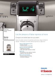
A<br />
Figure 1<br />
CA<br />
N L<br />
1 BURNER COOK<strong>IN</strong>G HOB<br />
ELECTRIC DIAGRAM KEY<br />
A Ignition coil<br />
PA Ignition switch<br />
CA Spark electrode<br />
M Terminal block<br />
M<br />
PA<br />
CA<br />
A<br />
Figure 2<br />
CA<br />
PA<br />
N L<br />
2 BURNER COOK<strong>IN</strong>G HOB<br />
ELECTRIC DIAGRAM KEY<br />
A Ignition coil<br />
PA Ignition switches group<br />
CA Spark electrode<br />
M Terminal block<br />
M<br />
PA<br />
5
6<br />
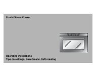
CLEARANCES:<br />
Installation clearances and protection of combustible surfaces shall comply with the<br />
current local regulations e.g. AG 601 (AS 5601) - Gas Installations code.<br />
50<br />
288<br />
490<br />
Important note:<br />
+ 0<br />
– 2<br />
DIMENSIONS:<br />
(Note: Also refer to Figure 3)<br />
510<br />
Figure 3<br />
This appliance shall not be used as a space heater, especially if installed in marine<br />
craft or caravans.<br />
General Dimensions<br />
Width 288 mm<br />
Depth 510 mm<br />
Depth Below Mounting Surface<br />
Cut-out Dimensions<br />
30 mm<br />
Width +0 270 – 2 mm<br />
Depth<br />
+0<br />
490 – 2 mm<br />
30<br />
270<br />
+ 0<br />
– 2<br />
50<br />
288<br />
490<br />
+ 0<br />
– 2<br />
510<br />
30<br />
270<br />
+ 0<br />
– 2
The installation shall comply<br />
with the dimensions in Figures<br />
3 and 4, bearing in mind that:<br />
■ A minimum clearance<br />
of 20 mm has to be<br />
kept between the bottom<br />
of the cooking hob and<br />
the top of an appliance<br />
or a shelf.<br />
To ensure this clearance<br />
mount the spacers<br />
supplied with the<br />
appliance as shown in<br />
the figure 5.<br />
■ A partition between the<br />
base of the hob and the<br />
cupboard below should<br />
be fitted 100 mm<br />
below the workbench<br />
surface if the cupboard is<br />
to be used for storage.<br />
20 mm<br />
Figure 5<br />
450 mm<br />
100 mm min<br />
Spacer<br />
Double-sided<br />
adhesive tape<br />
Figure 4<br />
750 mm<br />
50 mm min<br />
500 mm<br />
■ Overhead clearances -<br />
In no case shall the clearance<br />
between the highest<br />
part of the hob and a<br />
range hood be less than<br />
600 mm, or for an overhead<br />
exhaust fan, 750<br />
mm. Any other downward<br />
facing combustible<br />
surface less than 600 mm<br />
above the highest part of<br />
the hob shall be protected<br />
for the full width and<br />
depth of the cooking surface<br />
area in accordance<br />
with local regulations in<br />
force. However, in no<br />
case shall this clearance<br />
to any surface be less<br />
than 450 mm.<br />
7
8<br />
■ Side clearances - Where the dimensions from the periphery of the nearest<br />
burner to any vertical combustible surface is less than 200 mm, the surface<br />
shall be protected in accordance with local regulations in force to a height<br />
of not less than 150 mm above the hob for the full dimension (width or<br />
depth) of the cooking surface area.<br />
Where the dimensions from the periphery of the nearest burner to any horizontal<br />
combustible surface is less than 200mm, the horizontal surface shall<br />
be greater than 10mm below the surface of the hob, or the horizontal surface<br />
requirement above.<br />
■ Protection of combustible surfaces - Local regulations in force specifies<br />
that where required protection shall ensure that the surface temperature of<br />
the combustible surface does not exceed 65 °C above ambient. The fixing of<br />
5 mm thick ceramic tiles to the surface or attaching fire resistant material to<br />
the surface and covering with sheet metal with minimum thickness of 0.4<br />
mm should be satisfactory.<br />
A<br />
C<br />
Figure 6<br />
A<br />
A<br />
Figure 7<br />
B<br />
A<br />
D<br />
20 mm min.<br />
A<br />
40 mm max.<br />
FASTEN<strong>IN</strong>G THE COOKTOP<br />
(fig. 6)<br />
Each cooktop is supplied with a set of<br />
tabs and screws to fasten it on units<br />
with a working surface from 2 to 4 cm<br />
deep.<br />
The kit includes 4 tabs “A” and 4 selfthreading<br />
screws “B”.<br />
■ Cut the unit.<br />
■ Stretch gasket “D” over the edge of<br />
the hole made, being careful to<br />
overlay the junction edges.<br />
■ Turn the cooktop over and put tabs<br />
“A” (fig. 6) into the mountings; only<br />
tighten screws “B” a few turns.<br />
Make sure that the tabs are mounted<br />
correctly as shown in the figure 7.<br />
■ Put the cooktop into the hole cut<br />
into the unit and position it correctly.<br />
■ Put tabs “A” into place, tooth “C” of<br />
the tabs should go into the hole.<br />
■ Tighten screws “B” until the cooktop<br />
is completely secured.<br />
■ Using a sharp tool cut off the part<br />
of gasket “D” which protrudes from<br />
the cooktop. Take care not to<br />
damage the countertop.
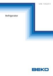
<strong>GAS</strong> SUPPLY:<br />
■ This appliance is suitable for use with Natural Gas or ULPG. (Check the<br />
“gas type” sticker attached to the appliance).<br />
■ For Natural Gas the gas supply must be regulated to obtain a pressure of 1 kPa<br />
with the two largest burners operating.<br />
■ For ULPG models connect the gas supply directly to the appliance test<br />
point adaptor (supplied with the conversion kit) and ensure that the supply pressure<br />
is regulated to 2.75 kPa.<br />
■ Do NOT force the ”elbow“ rotation prior to loosening nut.<br />
■ Do NOT over tighten the nut at the ”elbow“.<br />
1. After connecting the gas supply, check the piping and connections for leaks<br />
using a soap and water solution. The presence of bubbles indicates a leak, tighten<br />
or replace connections as appropriate.<br />
Warning: Do not use any naked flame to check for leaks.<br />
2. The operation of the appliance MUST be tested before leaving.<br />
3. Adjust the test point pressure or supply pressure to the value which is appropriate<br />
for the gas type.<br />
4. Turn on the appliance gas controls and light each burner. Check for a well<br />
defined blue flame without any yellow tipping. If any abnormality is evident then<br />
check that the burner cap is located properly and the injector nipple is aligned<br />
correctly.<br />
Figure 8<br />
Figure 9<br />
Test<br />
point<br />
Gas connection for<br />
NATURAL <strong>GAS</strong><br />
Gas inlet pipe<br />
Gasket<br />
Brass conical adaptor<br />
(Thread tight: use<br />
suitable seal)<br />
Gas regulator<br />
Gas connection for<br />
ULPG<br />
Test<br />
point<br />
Gas inlet pipe<br />
Gasket<br />
Brass conical adaptor<br />
(Thread tight: use<br />
suitable seal)<br />
Test point adaptor<br />
9
10<br />
5. Check the minimum burner setting by quickly rotating the gas control knob from<br />
the maximum to the minimum position, the flame must not go out. If adjustment<br />
is required carry out the “minimum burner setting adjustment" procedure<br />
described below.<br />
6. If satisfactory performance cannot be obtained, the installer shall check the installation<br />
and notify the local gas supply authority for a gas supply problem, or if it<br />
is an appliance problem, our Customer Service Centre should be called to obtain<br />
the nearest authorized Delonghi Service Agent.<br />
7. Where the appliance data plate cannot be easily read with the appliance in the<br />
installed position the duplicate data plate must be attached to adjacent surface<br />
and the duplicate Natural gas / ULPG conversion label should also be included<br />
where a Natural gas / ULPG conversion has been completed.<br />
<strong>IN</strong>STALLATION WITH A FLEXIBLE HOSE ASSEMBLY<br />
■ If this appliance has to be installed with a hose assembly, the installer shall<br />
refer to the network operator or gas supplòier for confirmation of the gas type,<br />
if in doubt.<br />
■ The gas supply connection point shall be accessible when the appliance is<br />
installed.<br />
■ Installation with a flexible hose assembly shall be carried out by using a hose<br />
with internal diameter of 16 mm minimum.<br />
The thread connection shall be Rp 1/2" (ISO 7-1) male.<br />
■ IMPORTANT WARN<strong>IN</strong>G: After connection the installer must check that the hose<br />
is not kinked, subjected to abrasion or permanently deformed.<br />
The installer must check also that the hose is not near (or in contact) with any<br />
hot surfaces e.g. base of metal hotplate, underbench oven etc.<br />
■ The hose assembly shall be as short as practicable and comply with relevant<br />
AS 5601/601 requirements.<br />
■ IMPORTANT WARN<strong>IN</strong>G: The installer shall ensure the hose assembly is restrained<br />
from accidental contact with the flue outlet of an underbench oven.<br />
Figure 10
TABLE FOR THE CHOICE OF THE <strong>IN</strong>JECTORS<br />
Natural Gas ULPG<br />
Test Point<br />
Pressure (kPa)<br />
1.0 2.75<br />
Burner Injector Orifice<br />
[mm]<br />
Gas Consumption<br />
[MJ/h]<br />
Injector Orifice<br />
[mm]<br />
Gas Consumption<br />
[MJ/h]<br />
Semi-rapid 1.12 6.30 0.70 6.30<br />
Rapid 1.45 10.40 0.91 10.80<br />
Triple ring 1.65 13.30 0.95 11.90<br />
(Note: Gas type sticker and data plate are attached to the underside of the base of<br />
the appliance.)<br />
11
12<br />
CONVERSION PROCEDURE (to convert to Natural gas or to<br />
ULPG) REPLAC<strong>IN</strong>G THE <strong>IN</strong>JECTORS<br />
The conversion procedure must be carried out only by an authorised person.<br />
This appliance is suitable for use with Natural gas or Universal LPG (check the “gas<br />
type” sticker attached to the appliance). The nominal gas consumption and injector<br />
size details are provided in table at page 11.<br />
To replace the injectors proceed as follows:<br />
■ Remove pan supports and burners from the cooktop.<br />
■ Using a spanner, remove the injector J (figs.11, 12) and replace it with one<br />
according to the gas type (see tables - page 11).<br />
■ Affix to the appliance the warning label stating that the cooktop has been converted<br />
for use with Natural gas/ULPG (supplied with the Natural gas/ULPG conversion<br />
kit). A second Natural gas/ULPG conversion label should also be affixed to an<br />
adjacent surface along with the duplicate data plate.<br />
IMPORTANT<br />
■ If the cooktop is suitable for use with Natural gas and must be converted for<br />
use with Universal LPG, before connecting to gas main remove the appliance<br />
gas regulator and replace with test point adaptor (see fig.8, 9).<br />
■ If the cooktop is suitable for use with Universal LPG and must be converted for<br />
use with Natural gas, before connecting to the gas main remove the appliance<br />
test point adaptor and replace with gas regulator (see figs. 8, 9).<br />
NOTE:<br />
Gas regulator and test point adaptor are supplied with the appliance (packed with<br />
conversion kit)<br />
The burners are designed so that regulation of primary air is not required.<br />
Figure 11 Figure 12<br />
J<br />
J
M<strong>IN</strong>IMUM BURNER SETT<strong>IN</strong>G ADJUSTMENT<br />
Check whether the flame spreads to all burner ports when the burner is lit with<br />
the gas tap set to the minimum position. If some ports do not light, increase the<br />
minimum gas rate setting.<br />
Check whether the burner remains lit even when the gas tap is turned quickly<br />
from the maximum to the minimum position. If the burner does not remain lit,<br />
increase the minimum gas rate setting.<br />
The procedure for adjusting the minimum gas rate setting is described below.<br />
For taps with adjusting screw inside the shaft (fig. 13):<br />
✓ using a screwdriver max. diameter 3 mm turn the screw inside the tap shaft until<br />
the flame setting is correct.<br />
For taps with adjusting screw on the body (fig. 14):<br />
✓ using a screwdriver turn screw "A" until the flame setting is correct.<br />
Normally for ULPG, fully tighten the adjustment screw.<br />
LUBRICAT<strong>IN</strong>G THE <strong>GAS</strong> TAP<br />
If a gas tap is difficult to turn, disassemble it, clean it carefully with petrol and spread<br />
a little high-temperature-resistant grease on it.<br />
These operations must be performed by an Authorized person/Service agent.<br />
Note: Servicing of this appliance is only to be carried out by Authorised Person.<br />
Figure 13 Figure 14<br />
A<br />
13
14<br />
CAUTION:<br />
USE and CARE<br />
■ This appliance must be used only for the task it has explicitly been designed<br />
for, that is for domestic cooking of foodstuffs. Any other form of usage is to<br />
be considered as inappropriate and therefore dangerous. Do not use this<br />
appliance as a space heater.<br />
■ Do NOT place combustible materials or products on this appliance at any<br />
time.<br />
■ Do NOT spray aerosols in the vicinity of this appliance while it is in use.<br />
■ Before using for the first time, clean the cooktop with warm soapy water.<br />
■ Use the coffee pot support to ensure that small cooking utensils are stable.<br />
■ IMPORTANT NOTE: This appliance shall not be used as a space heater,<br />
especially if installed in marine craft or caravans.<br />
Figure 15 Figure 16<br />
2<br />
NOTE:<br />
The models have a<br />
safety valve system fitted,<br />
(probe “T” close to the<br />
burner - see figure 22 at<br />
page 19) the flow of gas<br />
will be stopped if and<br />
5<br />
1 when the flame should<br />
accidentally go out.<br />
4 3<br />
All the appliances are fitted<br />
with a gas-lighter incorporated<br />
into the knob.<br />
6<br />
“2 BURNER COOK<strong>IN</strong>G HOB” (Fig. 15)<br />
The appliance is class 3 rated<br />
COOK<strong>IN</strong>G PO<strong>IN</strong>TS<br />
1. Semirapid burner (SR) - 6.30 MJ/h<br />
2. Rapid burner (R) - 10.40 MJ/h (NG)<br />
- 10.80 MJ/h (ULPG)<br />
CONTROL PANEL DESCRIPTION<br />
3. Burner 2 (R) control knob<br />
4. Burner 1 (SR) control knob<br />
“1 BURNER COOK<strong>IN</strong>G HOB” (Fig. 16)<br />
The appliance is class 3 rated<br />
COOK<strong>IN</strong>G PO<strong>IN</strong>T<br />
5. Triple ring burner - 13.30 MJ/h (NG)<br />
- 11.90 MJ/h (ULPG)<br />
CONTROL PANEL DESCRIPTION<br />
6. Triple ring burner control knob
LIGHT<strong>IN</strong>G <strong>GAS</strong> BURNERS<br />
■ Check that the electricity is switched on to allow spark ignition.<br />
■ Make sure that all controls are turned to zero.<br />
■ The gas flow to the burner is controlled by a tap incorporating a safety cut-off<br />
valve. If the burner flame should go out for some reason, the safety<br />
valve will automatically stop the gas flow. The switch of the electric ignition is<br />
incorporated in the knobs.<br />
■ You control the flow by turning the knob indicator to line up with the following<br />
symbols:<br />
– Symbol : tap closed (burner off)<br />
– Symbol : High (maximum)<br />
– Symbol : Low (minimum)<br />
To light one of the gas burners, follow the procedure LIGHT<strong>IN</strong>G <strong>GAS</strong> BURNERS on<br />
page 16.<br />
To reduce the gas flow to minimum, rotate the knob further anti-clockwise to point<br />
the indicator towards the small flame symbol.<br />
The maximum aperture position permits rapid boiling of liquids, whereas the minimum<br />
aperture position allows slower warming of food or maintaining boiling conditions<br />
of liquids.<br />
Other intermediate operating adjustments can be achieved by positioning the<br />
indicator between the maximum and minimum aperture positions, and never between<br />
the maximum aperture and closed positions.<br />
N.B. When the cooker top is not being used, set the gas knobs to their closed positions<br />
and also close the cock valve on the gas bottle or the main gas supply line.<br />
Figure 17 Figure 18<br />
15
16<br />
LIGHT<strong>IN</strong>G <strong>GAS</strong> BURNERS (FITTED WITH SAFETY CUT-OFF VALVE)<br />
In order to light the burner, you must:<br />
1 – Turn the knob fig. 18 in anti-clockwise direction up to the maximum aperture,<br />
push in and hold the knob; this will light the gas. If there is no mains electrical<br />
supply, bring a lighted match close to the burner.<br />
2 – Wait about ten seconds after the gaslights before releasing the knob (starting<br />
time for the valve).<br />
3 – Adjust the gas valve to the desired position.<br />
If the burner flame should go out, the safety valve will automatically stop the gas<br />
flow.<br />
To re-light the burner, first turn the oven control knob to position l, wait for at least<br />
1 minute and then repeat the lighting procedure.<br />
If after relighting the burner, the flame is still abnormal, turn the burner off and<br />
contact our Customer Service Centre to obtain the nearest authorized Delonghi Service<br />
Agent.<br />
GRILL FOR SMALL COOK-<br />
WARE (fig. 19)<br />
DE320G model only<br />
Put it on the semi-rapid burner (the<br />
smallest) grid when small cookware is<br />
being used to prevent the cookware<br />
from tipping over.<br />
Figure 19
COOK<strong>IN</strong>G H<strong>IN</strong>TS FOR <strong>GAS</strong> <strong>HOBS</strong><br />
■ The burners are different sizes, and can be used in different ways.<br />
■ The largest can be used for boiling, to seal meat or foods that are cooked quickly,<br />
and the smallest for stews and sauces.<br />
■ Always ensure that you use the correct size of saucepan.<br />
■ For fast boiling, make sure the flame just reaches the edge of the pan. Flames going<br />
up the side of the pan means wasted heat and the contents of the pan will take<br />
longer to boil.<br />
■ For optimum efficiency use a wok or pan no smaller than 230mm diameter.<br />
Burners Pan diameter<br />
Semirapid (SR) *<br />
12 to 20 cm<br />
Rapid (R) 22 to 26 cm<br />
Triple ring 24 to 28 cm<br />
(* ) with grill for small cookware:<br />
minimum diameter 6 cm.<br />
CORRECT USE OF TRIPLE-R<strong>IN</strong>G BURNER<br />
Figure 20<br />
do not use pans with concave or convex bases<br />
WARN<strong>IN</strong>G - VERY IMPORTANT NOTICE<br />
During use cooking vessels become hot. Pay special attention not to touch<br />
the hot vessels positioned on the cooking hob especially when operating the<br />
control knobs.<br />
■ The flat-bottomed pans are to be placed directly onto the pan-support.<br />
■ To use the WOK you must place the wok stand in the CORRECT position as<br />
shown in fig. 21.<br />
Figure 21<br />
WRONG CORRECT<br />
17
GENERAL ADVICE<br />
Cleaning and Maintenance<br />
■ Before you begin cleaning, you must ensure that the appliance is<br />
switched off.<br />
■ It is advisable to clean when the appliance is cold and especially when cleaning<br />
the enamelled parts.<br />
■ Avoid leaving alkaline or acidic substances (lemon juice, vinegar, etc.) on the surfaces.<br />
■ Avoid using cleaning products with a chlorine or acidic base.<br />
■ Do not use a steam cleaner because the moisture can get into the appliance<br />
thus make it unsafe.<br />
ENAMELLED PARTS<br />
All of the enamelled parts must be washed only with a sponge and soapy water<br />
or with non-abrasive products.<br />
Dry, preferably, with a microfibre or soft cloth.<br />
STA<strong>IN</strong>LESS STEEL<br />
The stainless steel parts should be rinsed with water and dried with a soft, clean<br />
cloth or chamois. In case of difficult spots, use normal non abrasive detergents<br />
available on the market or else a little warm vinegar.<br />
CLEAN<strong>IN</strong>G THE HOB<br />
Spillage on the hob can usually be removed by a damp soapy cloth. More obstinate<br />
stains can be removed by rubbing gently with a soapy scouring pad or mild<br />
household cleaner.<br />
<strong>GAS</strong> TAPS<br />
If the gas taps are not working properly, call our Customer Service Centre to obtain<br />
the nearest Authorized Delonghi Service Agent.<br />
BURNERS<br />
■ These parts can be removed and cleaned with appropriate products.<br />
■ After cleaning, the burners and their flame distributors must be well dried and<br />
correctly replaced.<br />
■ It is very important to check that the burner flame distributor and the cap has<br />
been correctly positioned - failure to do so can cause serious problems.<br />
■ In appliances with electric ignition keep the electrode clean so that the sparks<br />
always strike.<br />
■ Note: To avoid damage to the electric ignition do not use it when the burners<br />
are not in place.<br />
18
CORRECT REPLACEMENT OF THE BURNERS<br />
It is very important to check that the burner flame distributor F and the cap C has<br />
been correctly positioned (see figs. 22 and 26) failure to do so can cause serious<br />
problems.<br />
Check that the electrode “S” (fig. 22) is always clean to ensure trouble-free sparking.<br />
In the models with safety device, check that the probe “T” (fig. 22) next to each<br />
burner is always clean to ensure correct operation of the safety valves.<br />
Both the probe and ignition plug must be very carefully cleaned.<br />
C<br />
F<br />
Figure 22<br />
S<br />
T<br />
Figure 23<br />
Figure 24<br />
A B<br />
19
20<br />
TRIPLE R<strong>IN</strong>G BURNER<br />
The triple ring burner must be correctly positioned (see fig. 23); the burner rib<br />
must be located in position as shown by the arrow.<br />
Then position the cap A and the ring B (fig. 24 - 25).<br />
The burner correctly positioned must not rotate (fig.24).<br />
Figure 25 Figure 26
SERVICE AND MA<strong>IN</strong>TENANCE<br />
If the ignition spark fails to ignite or does not light the gas, check the following<br />
items before calling our Customer Service Centre to obtain the nearest Authorised<br />
Service Agent:<br />
■ Burner is reassembled and located correctly.<br />
■ Spark electrode and white ceramic are clean and dry.<br />
■ 240 VAC power supply is connected.<br />
Contact the local gas utility or our Customer Service Centre to obtain the nearest<br />
Authorized Service Agent.<br />
■ You can smell gas when all burners are turned on.<br />
■ The burners do not remain alight at the minimum marked setting.<br />
■ The burner flame is yellow or emits an unusual odour.<br />
Note that a bi-annual inspection of the appliance by an authorized service agent<br />
or your locate gas utility will ensure many years of trouble free operation of your<br />
appliance.<br />
21
Descriptions and illustrations in this booklet are given as simply indicative. The manufacturer reserves the right,<br />
considering the characteristics of the models described here, at any time and without notice, to make eventual<br />
necessary modifications for their construction or for commercial needs.<br />
23
cod. 1103202 ß1