ACDC Surge Protector - Technical Note - Blue Series (http://shop.acdc-dcac.eu/)
ACDC DCAC Company as manufacturer of Multi-Stage Surge Protectors has opened online web store that is available for worldwide buyers ( http://shop.acdc-dcac.eu ). Necessity about this step was requested from many of our customers which have required our sophisticated multi-stage surge protection for their electrical devices. Our online store provides quick and easy order and fast post-delivery to your door.
ACDC DCAC Company as manufacturer of Multi-Stage Surge Protectors has opened online web store that is available for worldwide buyers ( http://shop.acdc-dcac.eu ). Necessity about this step was requested from many of our customers which have required our sophisticated multi-stage surge protection for their electrical devices. Our online store provides quick and easy order and fast post-delivery to your door.

You also want an ePaper? Increase the reach of your titles
YUMPU automatically turns print PDFs into web optimized ePapers that Google loves.
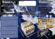
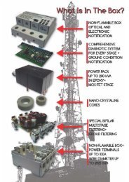
Diagnostic System<br />
Free Contact Alarm<br />
4. Operation Diagnostic System<br />
<strong>ACDC</strong> <strong>Surge</strong> <strong>Protector</strong>s Type -PI (780; 7100; 7125; 7200) <strong>Blue</strong><br />
<strong>Series</strong> have advanced operating diagnostics system with state<br />
indication of three protection stages (2,4 and 6). It also gave us<br />
information for appropriate installation and has special diagnostics<br />
for ground condition.<br />
Operating diagnostic system consists of 3 ledís:<br />
Green, Yellow and Red that indicates three operating<br />
conditions of the <strong>Surge</strong> <strong>Protector</strong>:<br />
4.1 Normal, 4.2 Damaged and 4.3 Fault Operating.<br />
4.1 Normal Operation:<br />
When the installation is made according to manufacturer<br />
instruction, Green and Yellow led are permanently ON.<br />
- Yellow Led is indication for correct stage no. 2<br />
- Green Led is indication for correct stage no. 4 and 6<br />
If the stages 2,4 and 6 are out of function, the stages<br />
1,3 and 7 are still provide a high grade bi-directional<br />
filtering along with ultimate fifth (5) protection<br />
stage.<br />
5. Free Contact Alarm<br />
Every <strong>ACDC</strong> <strong>Surge</strong> <strong>Protector</strong> Type-PI (780; 7100; 7125; 7200)<br />
<strong>Blue</strong> <strong>Series</strong> have free contact alarm as basic option. The alarm<br />
is active in two cases:<br />
1. When some of the protection stages (2, 4 or 6) are damaged<br />
or burned and Red Led is ON. Alarm contacts 1-3 are permanently<br />
closed.<br />
2. When impedance of equipotential ground toward n<strong>eu</strong>tral is<br />
not provided (pour grounding). Alarm contacts 1-3 are closing<br />
with frequency of 2Hz (0,5s) - Red led is blinking.<br />
<strong>acdc</strong>-<strong>dcac</strong>@<strong>acdc</strong>-<strong>dcac</strong>.<strong>eu</strong><br />
Sur SurGe MULTI-STAGE SURGE PROTECTION<br />
4.2 Damaged Unit:<br />
- If the surge protection stage no. 2 is burned or damaged the<br />
Yellow led will stop with continuous light.<br />
- If the surge protection stages 4 and 6 are burned or damaged<br />
the Green led will stop to lit (with continuous light) and Red led<br />
will start to lit with continuous light.<br />
4.3 Fault Operating:<br />
Blinking of Red light indicates that low impedance of<br />
equipotent ground toward n<strong>eu</strong>tral is not provided.<br />
In this situation the device can not guarantee 100% of<br />
protection of the electronic equipment. This situation is<br />
happening during an un appropriate installation or in the case<br />
when conditions of grounding is not satisfactory.<br />
If Red led is lit continuous and user decide to replace<br />
<strong>ACDC</strong> <strong>Surge</strong> <strong>Protector</strong> is recommended to do<br />
that with the same series.<br />
Free contacts are on the cover of the protector with contact<br />
no. 1 and 3. (see picture)<br />
The contact is a opto coupler with maximum of 70VDC and<br />
current of 10mA. In normal condition they are opened.<br />
+<br />
1 N.C 3<br />
-<br />
Page 8-11