68-0133 - Y8610U Intermittent Pilot Retrofit Kit - Air & Water
68-0133 - Y8610U Intermittent Pilot Retrofit Kit - Air & Water
68-0133 - Y8610U Intermittent Pilot Retrofit Kit - Air & Water

You also want an ePaper? Increase the reach of your titles
YUMPU automatically turns print PDFs into web optimized ePapers that Google loves.
<strong>Y8610U</strong> INTERMITTENT PILOT RETROFIT KIT<br />
initial power-up. Once this fuse has blown, the module does not<br />
work unless the vent damper is connected.<br />
To connect the plug-in vent damper:<br />
Remove and discard the vent damper plug from the<br />
module terminal strip.<br />
Using the wiring harness supplied, insert the matching<br />
pin plug into the receptacle on the module and the<br />
other end to the vent damper.<br />
To connect the D80B Vent Damper, follow the wiring<br />
diagrams supplied with the vent damper.<br />
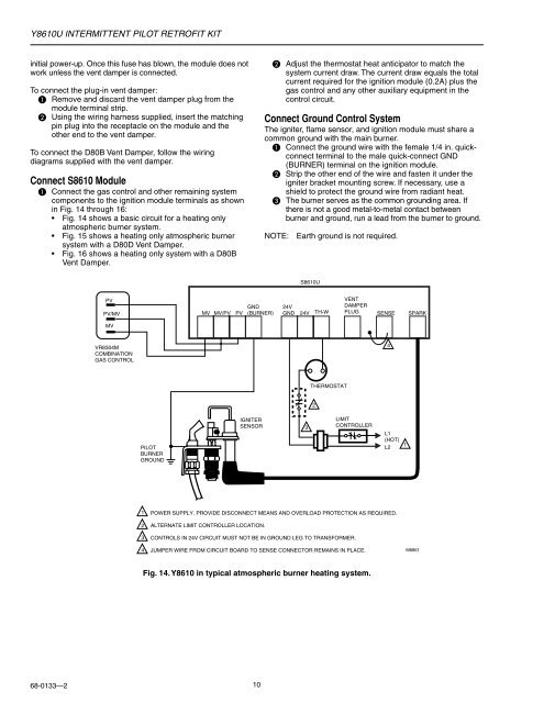
Connect S8610 Module<br />
Connect the gas control and other remaining system<br />
components to the ignition module terminals as shown<br />
in Fig. 14 through 16:<br />
• Fig. 14 shows a basic circuit for a heating only<br />
atmospheric burner system.<br />
• Fig. 15 shows a heating only atmospheric burner<br />
system with a D80D Vent Damper.<br />
• Fig. 16 shows a heating only system with a D80B<br />
Vent Damper.<br />
<strong>68</strong>-<strong>0133</strong>—2<br />
PV<br />
PV/MV<br />
MV<br />
VR8304M<br />
COMBINATION<br />
GAS CONTROL<br />
PILOT<br />
BURNER<br />
GROUND<br />
1<br />
2<br />
3<br />
4<br />
MV MV/PV PV<br />
GND<br />
(BURNER)<br />
IGNITER<br />
SENSOR<br />
10<br />
S8610U<br />
24V<br />
VENT<br />
DAMPER<br />
GND 24V TH-W PLUG SENSE SPARK<br />
3<br />
THERMOSTAT<br />
2<br />
LIMIT<br />
CONTROLLER<br />
4<br />
L1<br />
(HOT)<br />
L2<br />
POWER SUPPLY. PROVIDE DISCONNECT MEANS AND OVERLOAD PROTECTION AS REQUIRED.<br />
ALTERNATE LIMIT CONTROLLER LOCATION.<br />
CONTROLS IN 24V CIRCUIT MUST NOT BE IN GROUND LEG TO TRANSFORMER.<br />
JUMPER WIRE FROM CIRCUIT BOARD TO SENSE CONNECTOR REMAINS IN PLACE.<br />
Adjust the thermostat heat anticipator to match the<br />
system current draw. The current draw equals the total<br />
current required for the ignition module (0.2A) plus the<br />
gas control and any other auxiliary equipment in the<br />
control circuit.<br />
Connect Ground Control System<br />
The igniter, flame sensor, and ignition module must share a<br />
common ground with the main burner.<br />
Connect the ground wire with the female 1/4 in. quickconnect<br />
terminal to the male quick-connect GND<br />
(BURNER) terminal on the ignition module.<br />
Strip the other end of the wire and fasten it under the<br />
igniter bracket mounting screw. If necessary, use a<br />
shield to protect the ground wire from radiant heat.<br />
The burner serves as the common grounding area. If<br />
there is not a good metal-to-metal contact between<br />
burner and ground, run a lead from the burner to ground.<br />
NOTE: Earth ground is not required.<br />
Fig. 14. Y8610 in typical atmospheric burner heating system.<br />
1<br />
M<strong>68</strong>61