AR-162, AR-163, AR-201, AR-206 - OlsonBros
AR-162, AR-163, AR-201, AR-206 - OlsonBros
AR-162, AR-163, AR-201, AR-206 - OlsonBros

You also want an ePaper? Increase the reach of your titles
YUMPU automatically turns print PDFs into web optimized ePapers that Google loves.
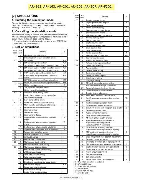
[7] SIMULATIONS<br />
1. Entering the simulation mode<br />
Perform the following procedure to enter the simulation mode.<br />
Clear key ! Interrupt key ! "0" key ! Interrupt key ! Main code !<br />
Start key ! Sub code ! Start key<br />
2. Cancelling the simulation mode<br />
When the clear all key is pressed, the simulation mode is cancelled.<br />
When the interruption key is pressed, the process is interrupted and the<br />
screen returns to the sub code entering display.<br />
* After canceling the simulation mode, be sure to turn OFF/ON the<br />
power and check the operation.<br />
3. List of simulations<br />
Main<br />
code<br />
Sub<br />
code<br />
<strong>AR</strong>-<strong>162</strong>, <strong>AR</strong>-<strong>163</strong>, <strong>AR</strong>-<strong>201</strong>, <strong>AR</strong>-<strong>206</strong>, <strong>AR</strong>-207, <strong>AR</strong>-F<strong>201</strong><br />
Contents "<br />
1 1 Mirror unit operation check<br />
2 Optical system sensor operation check<br />
2 1 SPF aging ADF<br />
2 SPF sensor operation check ADF<br />
3 SPF motor forward rotation operation check ADF<br />
4 SPF motor reverse rotation operation check ADF<br />
8 SPF paper feed solenoid operation check ADF<br />
9 RSPF reverse solenoid operation check AD<br />
10 RSPF paper exit gate solenoid operation<br />
check<br />
AD<br />
11 SPF PS release solenoid operation check ADF<br />
3 2 Shifter job separator sensor operation check AEF<br />
3 Shifter operation check E<br />
4 Job separator operation check AF<br />
11 Shifter Home Position Check E<br />
5 1 Operation panel display check<br />
2 Heater lamp lighting check, cooling fan<br />
motor operation check<br />
3 Copy lamp lighting check<br />
6 1 Paper feed solenoid operation check<br />
10 Main cassette semi-circular roller drive<br />
7 1 Aging with warmup time display<br />
4 Warmup saving<br />
6 Intermittent aging<br />
8 Warmup time display<br />
9 1 Duplex motor forward rotation operation<br />
check<br />
B<br />
2 Duplex motor reverse rotation operation<br />
check<br />
B<br />
4 Duplex motor rotation speed adjustment B<br />
5 Duplex motor switchback time adjustment B<br />
10 Toner motor operation check<br />
14 Trouble (except for U2) cancel<br />
16 U2 trouble cancel<br />
20 1 Maintenance counter clear<br />
21 1 Maintenance cycle setting<br />
2 Mini maintenance cycle setting<br />
22 1 Maintenance counter display<br />
2 Maintenance preset value display<br />
3 JAM memory display<br />
4 Total JAM counter display<br />
5 Total counter display<br />
6 Developing counter display<br />
7 Developing preset counter value display<br />
8 SPF counter display ADF<br />
9 Paper feed counter display<br />
12 Drum counter display<br />
14 Copier ROM version display<br />
Main<br />
code<br />
<strong>AR</strong>-<strong>162</strong> SIMULATIONS – 1<br />
Sub<br />
code<br />
Contents "<br />
22 15 Trouble memory display<br />
16 Duplex print counter display B<br />
17 Copy counter display<br />
18 Printer counter display A<br />
19 Electronic sort counter display AD<br />
21 Scanner counter display<br />
24 1 JAM memory, JAM counter clear<br />
2 Trouble memory clear<br />
4 SPF counter clear ADF<br />
5 Duplex counter clear B<br />
6 Paper feed counter clear<br />
7 Drum counter clear<br />
8 Copy counter clear<br />
9 Printer counter clear A<br />
10 Electronic sort counter clear AD<br />
13 Scanner counter clear<br />
25 1 Main motor operation check<br />
10 Polygon motor operation check<br />
26 1 Option switch display<br />
3 Auditor setting<br />
5 Counter mode setting<br />
6 Destination setting<br />
7 CRUM set value display<br />
10 Model name setting<br />
22 Language setting<br />
30 CE mark conformity control setting<br />
32 Fan rotation duty change state setup<br />
37 Cancel of stop at developer life over<br />
38 Cancel of stop at dram life over<br />
42 Transfer timing adjustment<br />
50 Black-white reversion function setup<br />
51 Sort/Group copy temporary stop function<br />
setup<br />
AD<br />
30 1 Machine sensor operation check<br />
41 2 OC document sensor adjustment C<br />
3 Document sensor light reception level display C<br />
42 1 Developing counter clear<br />
43 1 Fusing temperature setting<br />
46 1 Copy density level adjustment<br />
19 AE mode picture quality change<br />
48 1 Main scanning (front/rear) direction<br />
magnification ratio adjustment<br />
(Copy/FAX/OC-SPF common)<br />
2 OC mode sub scanning direction<br />
magnification ratio adjustment in copying<br />
5 SPF mode sub scanning direction<br />
magnification ratio adjustment in copying<br />
D<br />
50 1 Copy image lead edge position adjustment<br />
10 Paper off center adjustment<br />
13 OC mode document off center adjustment<br />
16 SPF mode document off center adjustment D<br />
18 Duplex memory reverse print adjustment B<br />
19 Duplex rear edge void adjustment B<br />
51 2 Resist amount adjustment<br />
63 1 Shading data check<br />
64 1 Self printing mode<br />
67 14 Printer Flash ROM Data Download A<br />
"A: Only when an option is installed.<br />
B: <strong>AR</strong>-<strong>206</strong>/207 only<br />
C: Other than <strong>AR</strong><strong>162</strong>/<strong>163</strong><br />
D: <strong>AR</strong>-207 only<br />
E: Other than <strong>AR</strong>-<strong>162</strong><br />
F: <strong>AR</strong>-F<strong>201</strong> only
4. Contents of simulations<br />
Main<br />
code<br />
Sub<br />
code<br />
Contents Details of operation<br />
1 1 Mirror unit operation check Used to execute scanning at the speed corresponding to the set<br />
magnification ratio.<br />
2 Optical system sensor<br />
operation check<br />
2 1 SPF aging<br />
<br />
2 SPF sensor operation<br />
check<br />
<br />
3 SPF motor forward<br />
rotation operation check<br />
<br />
4 SPF motor reverse<br />
rotation operation check<br />
<br />
8 SPF paper feed solenoid<br />
operation check<br />
<br />
9 RSPF reverse solenoid<br />
operation check<br />
<br />
10 RSPF paper exit gate<br />
solenoid operation check<br />
<br />
11 SPF PS release solenoid<br />
operation check<br />
<br />
Key operation Display<br />
Changing the magnification ratio:<br />
Fixed magnification ratio key<br />
ZOOM UP KEY, ZOOM DOWN<br />
KEY<br />
Used to check MHPS (Mirror home position sensor) ON/OFF state with<br />
the LED on the operation panel.<br />
Display<br />
<br />
MHPS: Paper empty LED<br />
Used to perform SPF document transport.<br />
The paper size is not detected. (Excluding postcards, extra large sheet<br />
of 1m or greater.)<br />
With SPF installed: Single transport operation<br />
With RSPF installed: Duplex transport operation<br />
Used to check sensors in SPF with the LED on the operation panel.<br />
Used to rotate the SPF motor forward for 10 sec.<br />
Used to rotate the SPF motor reversely for 10 sec.<br />
Set magnification ratio:<br />
Fixed magnification ratio LED<br />
ZOOM LED<br />
Key operation Display<br />
Changing the magnification ratio:<br />
Fixed magnification ratio key<br />
ZOOM UP KEY, ZOOM DOWN<br />
KEY<br />
Display<br />
<br />
PW1: JAM LED<br />
PW2: Paper empty LED<br />
PW3: Machine position JAM LED<br />
PW4: SPF JAM LED<br />
PL1: Manual paper feed tray select LED<br />
PL2: 2nd tray position JAM LED<br />
P-IN: SPF select LED<br />
SPF COVER OPEN: Main cassette select LED<br />
Used to drive the SPF paper feed solenoid (PSOL) at the cycle of 500<br />
msec ON and 500 msec OFF 20 times.<br />
Used to drive the RSPF reverse solenoid (RSOL) at the cycle of 500<br />
msec ON and 500 msec OFF 20 times.<br />
Used to drive the RSPF paper exit gate solenoid (GSOL) at the cycle of<br />
500 msec ON and 500 msec OFF 20 times.<br />
Used to drive the SPF PS release solenoid at the cycle of 500 msec ON<br />
and 500 msec OFF 20 times.<br />
<strong>AR</strong>-<strong>162</strong> SIMULATIONS – 2<br />
Set magnification ratio:<br />
Fixed magnification ratio LED<br />
ZOOM LED<br />
Initial<br />
value<br />
Set range<br />
100% 50 ! 200%<br />
100% 50 ! 200%
Main<br />
code<br />
Sub<br />
code<br />
3 2 Shifter job separator<br />
sensor operation check<br />
Contents Details of operation<br />
<br />
3 Shifter operation check<br />
<br />
4 Job separator operation<br />
check<br />
<br />
11 Shifter Home Position<br />
check<br />
<br />
5 1 Operation panel display<br />
check<br />
2 Heater lamp lighting<br />
check, cooling fan motor<br />
operation check<br />
Used to check the sensors state in the shifter job separator with the<br />
LED on the operation panel.<br />
Used to drive the shifter motor at the speed of printing of A4 (8-1/2 !<br />
11"). Pressing the clear all key or interrupt key moves the shifter to the<br />
home position.<br />
Used to drive the job separator one way. Pressing the clear all key or<br />
interrupt key stops the job separator at the home position.<br />
Used to drive the shifter motor<br />
Used to light all LED’s on the operation panel for 5 sec.<br />
Used to turn ON the heater lamp for 500 msec and OFF for 500 msec 5<br />
times. At the same time, the cooling fan is rotated at a high speed. After<br />
checking the heater lamp operation, the cooling fan motor rotate at a low<br />
speed.<br />
3 Copy lamp lighting check Used to light the copy lamp for 10 sec.<br />
6 1 Paper feed solenoid<br />
operation check<br />
10 Main cassette semicircular<br />
roller drive<br />
Display<br />
<br />
Shifter HP sensor: Machine position JAM LED<br />
Job separator HP sensor: SPF JAM LED<br />
Paper exit full sensor: 2nd tray position JAM LED<br />
Key operation<br />
The shifter is moved to the home position: Clear all key, interrupt key<br />
Key operation<br />
Stops at the home position: Clear all key, interrupt key<br />
Key operation<br />
Feed: Exposure up key or "3" key<br />
Return: Exposure down key or "4" key<br />
Move to Home Position: Magnification ratio display key or "5" key<br />
When the start key is pressed, the selected paper feed solenoid is<br />
driven at the cycle of 500 msec ON and 500 msec OFF 20 times.<br />
Key operation Display<br />
Solenoid selection:<br />
Tray select button<br />
<br />
Main cassette paper feed solenoid:<br />
Main cassette select LED<br />
Multi manual paper feed solenoid:<br />
Manual paper feed select LED<br />
No. 2 cassette paper feed solenoid:<br />
No. 2 cassette select LED<br />
No. 3 cassette paper feed solenoid:<br />
No. 3 cassette select LED<br />
<br />
No. 4 cassette paper feed solenoid:<br />
No. 4 cassette select LED<br />
<br />
Resist roller solenoid:<br />
Machine position JAM LED<br />
No. 2 cassette transport solenoid:<br />
No. 2 cassette position JAM LED<br />
No. 3 cassette transport solenoid:<br />
Machine position JAM LED + No. 2<br />
cassette position JAM LED<br />
<br />
No. 4 cassette transport solenoid:<br />
JAM LED<br />
<br />
Excute the simulation with the developer cartridge removed, used to<br />
rotate the semi-circular roller of the main cassette one turn to face it<br />
downward.<br />
<strong>AR</strong>-<strong>162</strong> SIMULATIONS – 3<br />
Initial<br />
value<br />
Set range
Main<br />
code<br />
Sub<br />
code<br />
7 1 Aging with warmup time<br />
display<br />
Contents Details of operation<br />
Execute the simulation input with the copier side cover open, then close<br />
the side cover, and the machine will start warming up. Warm up time is<br />
counted up every 2nd and it is displayed. After completion of warmup,<br />
count up is terminated. When the clear all key is pressed ready lamp is<br />
lighted and the copy quantity is entered and the start key is pressed,<br />
copying is made to make the set quantity of copies. At that time, the<br />
paper size does not matter.<br />
Initial<br />
value<br />
Set range<br />
1 ! 99<br />
4 Warmup saving Used to bring the machine to the ready state without warmup. 1 ! 99<br />
6 Intermittent aging After completion of warmup, counting is stopped and the ready lamp is<br />
lighted. When the copy quantity is entered and the start key is pressed,<br />
copying is made to make the set quantity of copies. After 3 sec standby,<br />
copying is made again to make the set quantity of copies. After that this<br />
operation is repeated. The paper size does not matter.<br />
8 Warmup time display Execute the simulation input with the copier side cover open, then close<br />
the side cover, and the machine will starts warming up. Warm up time is<br />
counted up every 2nd and it is displayed.<br />
9 1 Duplex motor forward<br />
rotation operation check<br />
<br />
2 Duplex motor reverse<br />
rotation operation check<br />
<br />
4 Duplex motor rotation<br />
speed adjustment<br />
<br />
5 Duplex motor switchback<br />
time adjustment<br />
<br />
10 Toner motor operation<br />
check<br />
14 Trouble (except for U2)<br />
cancel<br />
Key operation<br />
Copy quantity setting: Copy quantity keys<br />
Key operation<br />
Copy quantity setting: Copy quantity keys<br />
Used to rotate the duplex motor forward for 30 sec.<br />
Used to rotate the duplex motor reversely for 30 sec.<br />
The currently set duplex motor rotation speed set value is displayed.<br />
When the set value is entered and the start key is pressed, the set<br />
value is stored.<br />
The currently set duplex motor switchback time set value is displayed.<br />
When the set value is entered and the start key is pressed, the set<br />
value is stored.<br />
Used to operate the toner motor for 30 sec.<br />
Note: If this simulation is executed with the toner hopper installed, toner<br />
is automatically supplied to the developer. Be careful of overtoner.<br />
Used to cancel troubles except for U2.<br />
16 U2 trouble cancel Used to cancel U2 trouble.<br />
Key operation<br />
Duplex motor rotation speed set value: Copy quantity keys<br />
Key operation<br />
Duplex motor switchback time set value: Copy quantity keys<br />
20 1 Maintenance counter clear Used to clear the maintenance counter. "2<br />
21 1 Maintenance cycle setting Used to display the currently set maintenance cycle at the numbers<br />
shown at right. When the set value is entered and the start key is<br />
pressed, the set value is stored.<br />
Key operation/Display<br />
0: 2500 sheets 4: 150000 sheets<br />
1: 5000 sheets 5: FREE (999999 sheets)<br />
2: 15000 sheets 6: 10000 sheets<br />
3: 30000 sheets 7: 7500 sheets<br />
"2: Display after clearing each counter<br />
000 (0.75 sec) # Blank (0.35 sec) # 000 (0.75 sec) # Blank (1.0 sec) # Repetition<br />
<strong>AR</strong>-<strong>162</strong> SIMULATIONS – 4<br />
1 ! 99<br />
1 ! 99<br />
6 1 ! 13<br />
50 18 ! 76<br />
4 0 ! 6
Main<br />
code<br />
Sub<br />
code<br />
21 2 Mini maintenance cycle<br />
setting<br />
<br />
22 1 Maintenance counter<br />
display<br />
Contents Details of operation<br />
2 Maintenance preset value<br />
display<br />
Used to display the currently set mini maintenance cycle at the numbers<br />
shown at right. When the set value is entered and the start key is<br />
pressed, the set value is stored.<br />
Used to display the current maintenance counter value. !1<br />
Used to display the current maintenance preset value (set with SIM 21-<br />
1). !1<br />
3 JAM memory display Used to display a JAM generated during copying on the JAM position<br />
display on the operation panel. Max. 30 recent jams are stored.<br />
JAM No. 1 is displayed even when there is no JAM.<br />
4 Total JAM counter display Used to display the current total JAM counter value. !1<br />
5 Total counter display Used to display the current total counter value. !1<br />
6 Developing counter display Used to display the current developing unit counter value. !1<br />
7 Developing preset<br />
counter value display<br />
<br />
8 SPF counter display<br />
<br />
9 Paper feed counter<br />
display<br />
Used to display the current mini maintenance preset value (set with SIM<br />
21-2). !1<br />
Used to display the current SPF counter value. !1<br />
Used to display the current paper feed counter value for each paper<br />
feed port. !1<br />
Key operation<br />
Paper feed port selection: Tray select key<br />
12 Drum counter display Used to display the current drum counter value. !1<br />
14 Copier ROM version<br />
display<br />
Key operation/Display<br />
0: 2500 sheets 4: 30000 sheets<br />
1: 5000 sheets<br />
2: 10000 sheets<br />
3: FREE (999999 sheets)<br />
Key operation Display<br />
JAM history select:<br />
Magnification ratio display key<br />
The history number (1 # 30) is<br />
displayed on the display.<br />
The JAM position LED<br />
corresponding to the history<br />
number is lighted.<br />
Used to display the version number of the main ROM.<br />
Display<br />
(Example) When the ROM version is 4.01:<br />
004 " Blank " 001 " Blank " Repetition<br />
15 Trouble memory display Used to display the actually occurred trouble codes on the display on<br />
the operation panel. When the start key is pressed during the main code<br />
display, the sub code is displayed. Max. 20 recent trouble codes are<br />
stored.<br />
Key operation Display<br />
Sub code display: Start key Histories 1 # 10: The upper digit of<br />
Trouble code history<br />
select: Magnification ratio<br />
display key<br />
!1: Each counter display method<br />
To display 123456: 123 (0.75 sec) " Blank (0.35 sec) " 456 (0.75 sec) " Blank (1.0 sec) " repetition<br />
!2: Display after clearing each counter<br />
000 (0.75 sec) " Blank (0.35 sec) " 000 (0.75 sec) " Blank (1.0 sec) " Repetition<br />
<strong>AR</strong>-<strong>162</strong> SIMULATIONS – 5<br />
display “A” # “J” lights up.<br />
Histories 11 # 20: The upper digit of<br />
display “A” # “J” blinks.<br />
! Display without trouble code<br />
Main code: “– –”<br />
Sub code: “00”<br />
Initial<br />
value<br />
4<br />
Set range
Main<br />
code<br />
Sub<br />
code<br />
22 16 Duplex print counter<br />
display<br />
<br />
Contents Details of operation<br />
Used to display the current duplex print counter value. !1<br />
17 Copy counter display Used to display the current copy counter value. !1<br />
18 Printer counter display<br />
<br />
19 Electronic sort counter<br />
display <br />
Used to display the current printer counter value. !1<br />
Used to display the current electronic sort counter value. !1<br />
21 Scanner counter display Used to display the current scanner counter value.<br />
24 1 JAM memory, JAM<br />
counter clear<br />
Used to clear the JAM memory and the JAM counter. !2<br />
2 Trouble memory clear Used to clear the trouble memory. !2<br />
4 SPF counter clear<br />
<br />
5 Duplex counter clear<br />
<br />
Used to clear the SPF counter. !2<br />
Used to clear the duplex counter. !2<br />
6 Paper feed counter clear Used to clear the paper feed counter. !2<br />
7 Drum counter clear Used to clear the drum counter. !2<br />
8 Copy counter clear Used to clear the copy counter. !2<br />
9 Printer counter clear<br />
<br />
10 Electronic sort counter<br />
clear <br />
Used to clear the printer counter. !2<br />
Used to clear the electronic sort counter. !2<br />
13 Scanner counter clear Used to clear the scanner counter. !2<br />
25 1 Main motor operation<br />
check<br />
10 Polygon motor operation<br />
check<br />
Execute the simulation with the developer cartridge removed, and the<br />
main motor will rotate for 30 sec. At that time, the cooling motor rotates<br />
at a low speed.<br />
Used to drive the polygon motor for 30 sec.<br />
!2: Display after clearing each counter<br />
000 (0.75 sec) " Blank (0.35 sec) " 000 (0.75 sec) " Blank (1.0 sec) " Repetition<br />
<strong>AR</strong>-<strong>162</strong> SIMULATIONS – 6<br />
Initial<br />
value<br />
Set range
Main<br />
code<br />
Sub<br />
code<br />
Contents Details of operation<br />
26 1 Option switch display Used to display the installed option on the operation panel. (The LED<br />
corresponding to the installed option is lighted.)<br />
Key<br />
operation<br />
Display<br />
select:<br />
Magnification<br />
ratio display<br />
key<br />
3 Auditor setting Used to display the current auditor setting with the numbers at right.<br />
After entering the set value, press the start key, and the set value is<br />
stored.<br />
0: Built-in auditor<br />
1: Coin vendor<br />
2: Others<br />
Display<br />
<br />
When “A” is displayed:<br />
Shifter: Paper empty LED<br />
Job separator: JAM LED<br />
SPF: SPF select LED<br />
RSPF: SPF JAM LED<br />
Duplex mode: Main cassette select LED<br />
Simplex mode: Multi manual paper feed select LED<br />
MCU JMPER1: Top of the magnification ratio display<br />
MCU JMPER2: 2nd of the magnification ratio display<br />
MCU JMPER3: 3rd of the magnification ratio display<br />
MCU JMPER7: 4th of the magnification ratio display<br />
MCU JMPER7: 5th of the magnification ratio display<br />
MCU JMPER7: 6th of the magnification ratio display<br />
MCU JMPER7: 7th of the magnification ratio display<br />
MCU JMPER8: Bottom of the magnification ratio<br />
display<br />
When “b” is displayed:<br />
Cassette (2nd step): No. 2 cassette select LED<br />
Cassette (3rd step): No. 3 cassette select LED<br />
Cassette (4th step): No. 4 cassette select LED<br />
Memory installed: Paper empty LED<br />
FAX: JAM LED<br />
Printer: Main body JAM LED<br />
ERDH: Main cassette select LED<br />
16CPM: SPF JAM LED<br />
20CPM: SPF select LED<br />
Document sensor: Auto paper select LED<br />
Key operation/Display<br />
5 Counter mode setting Used to set the print counter mode in A3 or 11" " 17".<br />
Used to display the currently set counter value with the numbers at right.<br />
After entering the set value, press the start key, and the set value is<br />
stored.<br />
Key operation/Display<br />
0: Total/Developer = 2 counts Maintenance = 2 counts<br />
1: Total/Developer = 1 count Maintenance = 2 counts<br />
2: Total/Developer = 2 counts Maintenance = 1 count<br />
3: Total/Developer = 1 count Maintenance = 1 count<br />
<strong>AR</strong>-<strong>162</strong> SIMULATIONS – 7<br />
Initial<br />
value<br />
Set range<br />
0 0 ! 2<br />
0 0 ! 3
Main<br />
code<br />
Sub<br />
code<br />
Contents Details of operation<br />
26 6 Destination setting Used to display the current destination setting with the numbers at right.<br />
After entering the set value, press the start key, and the set value is<br />
stored.<br />
7 CRUM set value display The currently set value of CRUM is displayed with the following numbers:<br />
10 Model name setting Used to set the model name of the machine used with the following<br />
numbers. After entering the set value, press the start key and the set<br />
value is stored.<br />
22 Language setting Used to display the current setting of the language information with the<br />
number at right. After entering the set value, press the start key, and the<br />
set value is stored.<br />
30 CE mark conformity<br />
control setting<br />
32 Fan rotation duty change<br />
state setup<br />
Key operation/Display<br />
0: Japan 8: EX AB series<br />
1: USA (Inch series) 9: EX inch series (FC conformity)<br />
2: Canada (Inch series) 10: EX AB series (FC conformity)<br />
3: Germany 1 (AB series) (Australia, Newzealand)<br />
4: UK (AB series) 11: China (AB series)<br />
5: Not used 12: Taiwan (AB series)<br />
6: France (AB series) 13: Germany 2 (AB series)<br />
7: EX inch series<br />
Key operation/Display<br />
0: Not set 3: BTA-C<br />
1: BTA-A 99: Conv<br />
2: BTA-B<br />
Key operation/Display<br />
0: AL-1600 11: <strong>AR</strong>-N200 23: <strong>AR</strong>-<strong>162</strong>/S<strong>162</strong><br />
1: AL-1610 12: <strong>AR</strong>-N205 24: <strong>AR</strong>-<strong>163</strong>/S<strong>163</strong><br />
2: AL-<strong>162</strong>0 13: AL-<strong>162</strong>1 25: <strong>AR</strong>-<strong>201</strong>S<br />
3: AL-1640/AL-1641 14: AL-1650 26: <strong>AR</strong>-<strong>201</strong>/S<strong>201</strong><br />
4: <strong>AR</strong>-160/<strong>AR</strong>-S160 15: AL-1670 27: <strong>AR</strong>-<strong>206</strong>/S<strong>206</strong><br />
5: <strong>AR</strong>-161/<strong>AR</strong>-S161 16: <strong>AR</strong>-F200 28: <strong>AR</strong>-207<br />
6: <strong>AR</strong>-200S 17: DM-2000 29: <strong>AR</strong>F161<br />
7: <strong>AR</strong>-200/<strong>AR</strong>-S200 18: DM-2005 30: <strong>AR</strong>F<strong>201</strong><br />
8: <strong>AR</strong>-205/<strong>AR</strong>-S205 19: DM-<strong>201</strong>0<br />
9: <strong>AR</strong>-F160 20: DM-<strong>201</strong>5<br />
10: <strong>AR</strong>-F205<br />
Key operation/Display<br />
0: Japanese 4: Italian<br />
1: English 5: Dutch<br />
2: French 6: Swedish<br />
3: German 7: Spanish<br />
Used to display the current setting of CE mark conformity control with<br />
the number at right. After entering the set value, press the start key, and<br />
the set value is stored.<br />
Key operation/Display<br />
0: CE mark control OFF<br />
1: CE mark control ON<br />
The currently set fan motor rotation duty is displayed with the following<br />
numbers. After entering the set value, press the start key to store the<br />
set value.<br />
Key operation/Display<br />
0: Operating 50%, standby 30%<br />
1: Operating 80%, standby 50%<br />
<strong>AR</strong>-<strong>162</strong> SIMULATIONS – 8<br />
Initial<br />
value<br />
Set range<br />
0 0 ! 11<br />
0 0 ! 30<br />
0 0 ! 7<br />
0 0 ! 1<br />
0 0.1
Main<br />
code<br />
Sub<br />
code<br />
26 37 Cancel of stop at<br />
developer life over<br />
38 Cancel of stop at drum<br />
life over<br />
<br />
Contents Details of operation<br />
The currently set value is displayed. Enter a set value and press the<br />
ST<strong>AR</strong>T key, then the set value is registered.<br />
The currently set value is displayed. After entering the set value, press<br />
the start key to store the set value.<br />
42 Transfer timing adjustment After completion of warm up, shading is performed and the currently set<br />
transfer timing adjustment value is displayed.<br />
50 Black-white reversion<br />
function setup<br />
51 Sort/Group copy<br />
temporary stop function<br />
setup<br />
<br />
30 1 Machine sensor operation<br />
check<br />
41 2 OC document sensor<br />
adjustment<br />
<br />
Key operation/Display<br />
0: Stops the machine at developer life over.<br />
1: Does not stop the machine at developer life over.<br />
Key operation/Display<br />
0: The machine stops at drum life over.<br />
1: The machine does not stop at drum life over.<br />
Key operation<br />
Transfer timing adjustment value: Copy quantity keys<br />
“1”: 240 ms<br />
“3”: 260 ms<br />
“5”: 280 ms<br />
“7”: 300 ms<br />
“9”: 320 ms<br />
The current setup of black-white reversion is displayed with the following<br />
numbers. After entering the set value, press the start key to store the<br />
set value.<br />
Key operation/Display<br />
0: Black-white reversion function enabled<br />
1: Black-white reversion function disabled<br />
Used to set whether temporary stop for every 250-sheet print (150-sheet<br />
print when the job separator is installed) is made or not during copying<br />
with the sort/group function. The current setup is displayed with the<br />
following numbers. After entering the set value, press the start key to<br />
store the set value.<br />
0: Does not stop.<br />
1: Stops.<br />
Key operation/Display<br />
Used to check the sensors in the machine transport system with LED on<br />
the operation panel.<br />
Display<br />
<br />
Paper entry sensor: Machine position JAM LED<br />
Duplex sensor: SPF JAM LED <br />
Paper exit sensor: JAM LED<br />
No. 2 cassette transport sensor: No. 2 cassette position LED<br />
No. 3 cassette transport sensor: No. 3 cassette position LED<br />
<br />
No. 4 cassette transport sensor: No. 4 cassette position LED<br />
<br />
Drum initial SW: DRUM LED<br />
Used to read the document sensor input value with paper and perform<br />
the sensor detection level adjustment. For the adjustment procedure of<br />
the document sensor input value, refer to the previous descriptions.<br />
<strong>AR</strong>-<strong>162</strong> SIMULATIONS – 9<br />
Initial<br />
value<br />
Set range<br />
1 0 ! 1<br />
0 0 ! 1<br />
5 1, 3, 5, 7, 9<br />
0 0.1<br />
1 0.1
Main<br />
code<br />
Sub<br />
code<br />
41 3 Document sensor light<br />
reception level display<br />
Contents Details of operation<br />
<br />
Used to display the light reception level and the detection level of the<br />
document sensor. (The sensor level adjusted with SIM 41-2 is displayed.)<br />
42 1 Developing counter clear Used to clear the Developing counter. !2<br />
43 1 Fusing temperature setting Used to display the current setting of the fusing temperature at right.<br />
After selecting the fusing temperature with the magnification ratio display<br />
key, press the start key, and the set value is stored. The set range is<br />
155 " 190˚C. Use the magnification ratio key to adjust the value by –5˚C.<br />
46 1 Copy density level<br />
adjustment<br />
19 AE mode picture quality<br />
change<br />
48 1 Main scanning (front/rear)<br />
direction magnification<br />
ratio adjustment<br />
(Copy/FAX/OC-SPF<br />
common)<br />
2 OC mode sub scanning<br />
direction magnification<br />
ratio adjustment in<br />
copying<br />
Key operation Display<br />
Light reception/Detection<br />
level select: Magnification<br />
ratio display key<br />
Sensor select: Auto<br />
magnification ratio select key<br />
After completion of warmup, shading is performed and the currently set<br />
copy density level is displayed. For the adjustment procedure, refer to<br />
the previous descriptions.<br />
The currently set AE picture quality mode (gamma table) is displayed<br />
with the following set values. Enter a set value and press the ST<strong>AR</strong>T<br />
key, then the set value will be inputted.<br />
After completion of warmup, shading is performed and the currently set<br />
main scanning (front/rear) direction magnification ratio adjustment and<br />
the OC mode document center off adjustment are performed. For the<br />
adjustment procedure, refer to the previous descriptions.<br />
After completion of warmup, shading is performed and the currently set<br />
OC mode sub scanning direction magnification ratio adjustment in<br />
copying is performed. For the adjustment procedure, refer to the<br />
previous descriptions.<br />
!2: Display after clearing each counter<br />
000 (0.75 sec) # Blank (0.35 sec) # 000 (0.75 sec) # Blank (1.0 sec) # Repetition<br />
Display at the 3rd digit<br />
“A”: Light reception level display<br />
“b”: Document detection level display<br />
Sensor A: A3 (11 $ 17) document<br />
size LED<br />
Sensor B: A4 (8 1/2 $ 14) document<br />
size LED<br />
Sensor C: A4R (8 1/2 $ 11)<br />
document size LED<br />
Sensor D: B4 (8 1/2 $ 5 1/2)<br />
document size LED<br />
Key operation<br />
Fusing temperature select: Magnification ratio display key<br />
Key operation Display<br />
Mode select:<br />
Exposure mode select<br />
key<br />
Copy density level:<br />
Copy quantity keys<br />
Key operation/Display<br />
1: Picture quality priority mode<br />
2: Toner consumption priority mode<br />
<br />
Auto mode: AUTO LED<br />
Manual mode: MANUAL LED<br />
Photo mode: PHOTO LED<br />
Toner save mode: MANUAL + PHOTO LED<br />
AETS mode: AUTO + PHOTO LED<br />
Key operation Display<br />
Adjustment mode<br />
select: Magnification<br />
ratio display key<br />
Manual main scanning<br />
direction magnification<br />
ratio adjustment<br />
Set value: Copy<br />
quantity keys<br />
Auto magnification ratio adjustment:<br />
AUTO LED<br />
Manual magnification ratio adjustment:<br />
MANUAL LED<br />
OC mode document center off adjustment:<br />
PHOTO LED<br />
Key operation<br />
OC mode sub scanning direction magnification ratio in copying:<br />
Copy quantity keys<br />
<strong>AR</strong>-<strong>162</strong> SIMULATIONS – 10<br />
Initial<br />
value<br />
Set range<br />
170 155 " 190<br />
48 1 " 99<br />
1 1 " 2<br />
58 1 " 99<br />
50 1 " 99
Main<br />
code<br />
Sub<br />
code<br />
48 5 SPF mode sub scanning<br />
direction magnification<br />
ratio adjustment in<br />
copying<br />
Contents Details of operation<br />
<br />
50 1 Copy image position<br />
adjustment<br />
10 Paper off center<br />
adjustment<br />
13 OC mode document off<br />
center adjustment<br />
16 SPF mode document off<br />
center adjustment<br />
<br />
After completion of warmup, shading is performed and the currently set<br />
SPF mode sub scanning direction magnification ratio adjustment in<br />
copying is performed. For the adjustment procedure, refer to the<br />
previous descriptions.<br />
Key operation Display<br />
Adjustment mode select:<br />
Exposure mode select key<br />
Set value:<br />
Copy quantity keys<br />
Auto: SPF mode sub scanning<br />
direction magnification ratio in copying<br />
Manual: RSPF mode sub scanning<br />
direction magnification ratio in copying<br />
After completion of warmup, shading is performed and the currently set<br />
value is displayed. For the adjustment procedure, refer to the previous<br />
descriptions.<br />
Key operation Display<br />
Adjustment mode<br />
select:<br />
Exposure mode<br />
select key<br />
Set value:<br />
Copy quantity keys<br />
Auto: Copy lead edge adjustment<br />
Manual: SPF lead edge adjustment<br />
<br />
Photo: Main cassette lead edge void<br />
adjustment<br />
Auto + Manual: Left edge void adjustment<br />
Auto + Photo: Rear edge void adjustment<br />
Auto + Manual + Photo: Option cassette<br />
lead edge void adjustment<br />
Manual + Photo: Multi bypass tray lead<br />
edge void adjustment<br />
None: Duplex lead edge void adjustment<br />
<br />
Exposure 1: Print start position adjustment<br />
Exposure 3: Duplex lead edge adjustment<br />
<br />
Exposure 5: Duplex rear edge void<br />
adjustment <br />
After completion of warmup, shading is performed and the currently set<br />
off center adjustment of each paper feed port is displayed. For the<br />
adjustment procedure, refer to the previous descriptions.<br />
Key operation Display<br />
Paper feed port tray<br />
select: Tray select key<br />
Off center adjustment<br />
value: numeric keys<br />
Main cassette:<br />
Main cassette select LED<br />
Manual paper feed:<br />
Manual feed select LED<br />
No. 2 cassette:<br />
No. 2 cassette select LED<br />
No. 3 cassette:<br />
No. 3 cassette select LED<br />
<br />
No. 4 cassette:<br />
No. 4 cassette select LED<br />
<br />
Duplex: None <br />
After completion of warmup, shading is performed and the currently set<br />
off center adjustment value for the document in OC reading is displayed.<br />
For the adjustment procedure, refer to the previous descriptions.<br />
Key operation<br />
Off center adjustment value: Copy quantity keys<br />
After completion of warmup, shading is performed and the currently set<br />
off center adjustment value for the document in SPF reading is<br />
displayed. For the adjustment procedure, refer to the previous<br />
descriptions.<br />
Key operation<br />
Off center adjustment value: Copy quantity keys<br />
<strong>AR</strong>-<strong>162</strong> SIMULATIONS – 11<br />
Initial<br />
value<br />
33<br />
45<br />
55<br />
77<br />
18<br />
48<br />
40<br />
18<br />
18<br />
20<br />
55<br />
60<br />
60<br />
Set range<br />
1 ! 99<br />
1 ! 99<br />
50 1 ! 99<br />
50 1 ! 99<br />
61 1 ! 99
Main<br />
code<br />
Sub<br />
code<br />
50 18 Duplex memory reverse<br />
position adjustment<br />
Contents Details of operation<br />
<br />
50 19 Duplex rear edge void<br />
adjustment<br />
<br />
After completion of warmup, shading is performed and currently set<br />
value is displayed<br />
After completion of warmup, shading is performed and currently set<br />
value is displayed.<br />
51 2 Resist amount adjustment After completion of warmup, shading is performed and the currently set<br />
resist amount adjustment value is displayed.<br />
63 1 Shading data check The copy lamp is shifted to the shading position and it is lighted with the<br />
reference voltage at AD conversion fixed (Vref– = 0.5V, Vref+ = 4.5V).<br />
The level of one pixel at the center at that time is displayed.<br />
64 1 Self print mode Disregards the optical system and performs self printing in 1 by 2mode.<br />
67 14 Printer Flash ROM<br />
Data Download<br />
<br />
Key operation<br />
Memory reverse position adjustment value:<br />
Copy quantity keys<br />
Key operation Display<br />
Adjustment mode select:<br />
Exposure mode select key<br />
Auto: SPF/R-SPF rear edge void<br />
Set value:<br />
Manual: R-SPF off center<br />
Copy quantity keys Photo: R-SPF lead edge void<br />
Key operation Display<br />
Resist amount adjustment:<br />
Copy quantity keys<br />
Adjustment mode select:<br />
Exposure mode select key<br />
Display section: Shading data<br />
Auto: Main cassette<br />
Manual: 2nd tray<br />
Photo: Manual feed tray<br />
Auto + Manual: Duplex <br />
Auto + Photo: RSPF <br />
Display<br />
The machine enters the version up mode of the printer control PWB<br />
flash ROM.<br />
For details, refer to the later.<br />
<strong>AR</strong>-<strong>162</strong> SIMULATIONS – 12<br />
Initial<br />
value<br />
Set range<br />
58 1 ! 99<br />
37<br />
52<br />
70<br />
50<br />
1<br />
50<br />
50<br />
48<br />
1 ! 99<br />
1 ! 99<br />
(6 ! 94 for<br />
the duplex<br />
only)
[8] USER PROGRAMS<br />
The user programs allow the parameters of certain functions to be set, changed, or canceled as desired.<br />
1. List of user programs<br />
This copier has the following user programs.<br />
Program name<br />
Program<br />
No<br />
Auto clear time 1<br />
Preheat mode 2<br />
Auto power shutoff<br />
timer<br />
Stream feeding<br />
mode*<br />
Auto power shutoff<br />
setting<br />
Border line for 2<br />
in 1 or 4 in 1*<br />
3<br />
4<br />
Description Default Parameters<br />
Sets the auto clear time. The copier returns to the initial settings<br />
when the auto clear time elapses after the last copy is made.<br />
Sets the time that elapses before the copier enters the preheat<br />
mode after any operation is made.<br />
Sets the time that elapses before the copier enters the auto<br />
power shut-off mode after any operation is made.<br />
Enables or disables the stream feeding mode when an optional<br />
SPF or RSPF is installed.<br />
5 Enables or disables the auto power shut-off mode. ON<br />
6<br />
Enables or disables the border line which is printed in 2 in 1 or 4<br />
in 1 copying when an electronic sorting kit and an SPF or RSPF<br />
are installed.<br />
Rotation copy* 7 Enables or disables rotation of original images. ON<br />
Auto paper<br />
select mode<br />
Auto tray<br />
switching<br />
Auditing mode 10<br />
Account number<br />
entry<br />
Account number<br />
change<br />
Account number<br />
deletion<br />
Number of<br />
copies per<br />
account<br />
8 Enables or disables the auto paper selection. ON<br />
9<br />
Enables or disables the automatic tray switching which occurs<br />
when paper in a tray runs out. (This switching cannot switch to<br />
the bypass tray.)<br />
Enables or disables the auditing mode, which controls access to<br />
copier.<br />
60sec<br />
90sec<br />
30min<br />
OFF<br />
OFF<br />
ON<br />
OFF<br />
0(OFF)<br />
1(30sec)<br />
2(60sec)<br />
3(90sec)<br />
4(120sec)<br />
5(10sec)<br />
0(OFF)<br />
1(30sec)<br />
2(60sec)<br />
3(90sec)<br />
4(120sec)<br />
1(30min)<br />
2(60min)<br />
3(90min)<br />
4(120min)<br />
5(240min)<br />
0(OFF)<br />
1(ON)<br />
0(OFF)<br />
1(ON)<br />
0(OFF)<br />
1(ON)<br />
0(OFF)<br />
1(ON)<br />
0(OFF)<br />
1(ON)<br />
0(OFF)<br />
1(ON)<br />
0 (OFF)<br />
1 (ON)<br />
11 Registers accounts for auditing mode. – –<br />
12 Changes account numbers for auditing mode. – –<br />
13 Deletes accounts for auditing mode. – –<br />
14<br />
Displays the total number of copies made against account<br />
numbers.<br />
– –<br />
Resetting account 15 Resets all audit accounts or resets any desired individual account. – –<br />
Erase width<br />
adjustment*<br />
16 Sets the amount of the edge erase and center erase areas. 10mm[1/2"]<br />
<strong>AR</strong>-<strong>162</strong> USER PROGRAMS – 1<br />
0(0mm[0"])<br />
1(5mm[1/4"])<br />
2(10mm[1/2"])<br />
3(15mm[3/4"])<br />
4(20mm[1"])
Program name<br />
Layout in 2 in 1<br />
copy*<br />
Layout in 4 in 1<br />
copy*<br />
Offset of paper<br />
output tray<br />
Image rotation in<br />
duplex copying<br />
Location of the<br />
margin*<br />
Program<br />
No<br />
17<br />
18<br />
19<br />
20<br />
Selects a pattern for 2 in 1 copying.<br />
Selects a pattern for 4 in 1 copying.<br />
Description Default Parameters<br />
Enables or disables the offset function of the paper output tray.<br />
The offset function can be specified respectively for the upper<br />
and lower areas separated by an optional job separator tray kit.<br />
Enables or disables image rotation (180˚) of the front side in onesided<br />
to two-sided copying or two-sided to one-sided copying.<br />
22 Selects the location of the expanded margin. Left<br />
! These programs do not affect the copier functions unless certain optional equipment is installed.<br />
2. Setting the user programs<br />
1) Press and hold the light key for more than 5 seconds until all the<br />
alarm indicators ( , , , , and ) blink and "- -" appears<br />
in the copy quantity display.<br />
2) Enter a program number using the numeric keys.<br />
! The selected program number will blink in the copy quantity display.<br />
! If a mistake is made in steps 2) to 4), press the CLE<strong>AR</strong> key.<br />
The copier will return to step 2).<br />
For example, to change the setting of the auto power shut-off timer,<br />
press key 3.<br />
3) Press the ST<strong>AR</strong>T key.<br />
! For programs 1 to 9 and 16 to 19, the entered program number<br />
will be steadily lit on the left side of the copy quantity display<br />
and the currently selected parameter number for the program<br />
will blink on the right side.<br />
! For programs 10 to 15 (programs for auditing accounts), the<br />
display varies with the program number.<br />
4) Select the desired parameter using the numeric keys.<br />
! The entered parameter number will blink on the right side of the<br />
copy quantity display.<br />
! The parameters are shown in the table below.<br />
For example, to change the setting of the auto power shut-off timer to<br />
60 min., press key 2.<br />
!! In European countries, the default setting of the preheat mode is 1<br />
(30 sec.). For other programs, factory-default settings in these<br />
countries are same to those shown above with an asterisk (!).<br />
Note: If you select "0" (OFF) in a program, the corresponding function<br />
will be disabled.<br />
5) Press the ST<strong>AR</strong>T key.<br />
! The right-hand number in the copy quantity display will be<br />
steadily lit and the entered value will be stored.<br />
6) To continue with other user programs, press the PRESS key and<br />
then repeat steps 2 to 5. To exit the user program mode, press<br />
the light key.<br />
! All the alarm indicators will go out.<br />
<strong>AR</strong>-<strong>162</strong> USER PROGRAMS – 2<br />
Pattern 1<br />
Pattern 1<br />
Upper ON,<br />
Lower ON<br />
OFF<br />
3. Toner cartridge life<br />
1(Pattern 1)<br />
2(Pattern 2)<br />
1(Pattern 1)<br />
2(Pattern 2)<br />
3(Pattern 3)<br />
4(Pattern 4)<br />
0(Upper OFF, Lower OFF)<br />
1(Upper ON, Lower On)<br />
2(Upper ON, Lower OFF)<br />
3(Upper OFF, Lower On)<br />
0(OFF)<br />
1(ON)<br />
1(Left)<br />
2(Top)<br />
To find out the approximate quantity of toner remaining, follow the procedure<br />
below.<br />
1) Press and hold the light key for more than 5 seconds until all the<br />
alarm indicators ( , , , , and ) blink and "- -" appears<br />
in the copy quantity display.<br />
2) Press and hold the copy ratio display key for more than 5<br />
seconds.<br />
! The approximate quantity of toner remaining will be indicated as<br />
a percent in the copy quantity display. ("100", "75", "50", "25",<br />
"10" or "LO" is displayed. When "LO" is displayed, the toner is<br />
down to less than 10%.)<br />
3) Press the light key.<br />
! All the alarm indicators will go out.
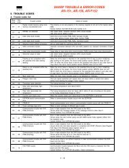
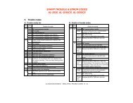
[9] TROUBLE CODE LIST<br />
1. Trouble code list<br />
Trouble<br />
code<br />
Trouble content<br />
E1 00 E-Sort board communication trouble<br />
10 E-Sort board trouble<br />
11 E-Sort ASIC error<br />
12 E-Sort CODEC error<br />
13 E-Sort flash ROM error<br />
14 E-Sort RAM error<br />
15 E-Sort page memory error<br />
16 E-Sort SIMM error<br />
17 Rotation RAM error<br />
80 E-Sort board communication trouble (Protocol)<br />
81 E-Sort board communication trouble (Parity)<br />
82 E-Sort board communication trouble (Overrun)<br />
84 E-Sort board communication trouble (Framing)<br />
88 E-Sort board communication trouble (Time-out)<br />
E7 03 LSU trouble<br />
04 CCD white level trouble<br />
05 CCD black level trouble<br />
F1 06 Shifter motor trouble<br />
F2 04 CRUM data read trouble<br />
F5 02 Copy lamp error<br />
F6 00 FAX board communication trouble<br />
10 FAX board trouble<br />
80 FAX board communication trouble (Protocol)<br />
81 FAX board communication trouble (Parity)<br />
82 FAX board communication trouble (Overrun)<br />
84 FAX board communication trouble (Framing)<br />
88 FAX board communication trouble (Time-out)<br />
F9 00 Printer PWB communication trouble<br />
10 Printer PWB trouble<br />
80 Printer PWB communication trouble (Protocol)<br />
81 Printer PWB communication trouble (Parity)<br />
82 Printer PWB communication trouble (Overrun)<br />
84 Printer PWB communication trouble (Framing)<br />
88 Printer PWB communication trouble (Time-out)<br />
H2 00 Thermistor open detection<br />
H3 00 Heat roller abnormally high temperature<br />
H4 00 Heat roller abnormally low temperature<br />
L1 00 Mirror base feed trouble<br />
L3 00 Mirror base return trouble<br />
L4 01 Main motor lock<br />
10 Job separator motor abnormality<br />
L6 10 Polygon motor lock<br />
L8 01 Zero cross pulse (FW) trouble<br />
U2 04 EEPROM serial communication error<br />
11 Counter check sum error<br />
12 Adjustment value check sum error (EEPROM)<br />
40 CRUM communication error<br />
U3 29 Mirror base home position error<br />
U9 00 Operation control PWB communication trouble<br />
80 Operation control PWB communication trouble<br />
(Protocol)<br />
81 Operation control PWB communication trouble<br />
(Parity)<br />
82 Operation control PWB communication trouble<br />
(Overrun)<br />
84 Operation control PWB communication trouble<br />
(Framing)<br />
88 Operation control PWB communication trouble (Timeout)<br />
U95 Operation control PWB connection error<br />
U99 Operation control PWB connection error<br />
2. Details of trouble codes<br />
Main<br />
code<br />
Sub<br />
code<br />
<strong>AR</strong>-<strong>162</strong> TROUBLE CODE LIST – 1<br />
Detail of trouble<br />
E1 00 Content Communication trouble between<br />
MCU and E-Sort.<br />
Detail Communication setup error,<br />
framing, parity, protocol error<br />
Cause E-Sort PWB connector<br />
disconnection<br />
E-Sort PWB MCU PWB harness<br />
failure<br />
E-Sort Motherboard connector pin<br />
breakage.<br />
E-Sort PWB ROM defect, data<br />
failure<br />
Check and<br />
remedy<br />
Check the connectors and harness<br />
of the E-Sort PWB and the MCU<br />
PWB.<br />
Check grounding of the machine.<br />
Check the ROM of the E-Sort<br />
PWB.<br />
10 Content E-Sort PWB trouble<br />
Detail Communication trouble between<br />
MCU and E-Sort<br />
Cause E-Sort PWB connector<br />
disconnection<br />
E-Sort PWB MCU PWB harness<br />
failure<br />
E-Sort Motherboard connector pin<br />
breakage.<br />
E-Sort PWB ROM defect, data<br />
failure<br />
Check and<br />
remedy<br />
Check the connectors and harness<br />
of the E-Sort PWB and the MCU<br />
PWB.<br />
Check grounding of the machine.<br />
Check the ROM of the E-Sort<br />
PWB.<br />
11 Content E-Sort PWB ASIC error<br />
Detail E-Sort PWB ASIC abnormality<br />
Cause An ASIC abnormality is detected<br />
in the E-Sort PWB.<br />
Control circuit hung up due to<br />
noises<br />
ASIC peripheral circuit error
Main<br />
code<br />
Sub<br />
code<br />
E1 11 Check and<br />
remedy<br />
Detail of trouble<br />
Replace the E-Sort PWB.<br />
Check grounding of the machine.<br />
12 Content E-Sort PWB CODEC error<br />
Detail E-Sort PWB CODEC error<br />
Cause A CODEC error is detected in the<br />
E-Sort PWB.<br />
Control circuit hung up due to<br />
noises<br />
CODEC peripheral circuit error<br />
Check and<br />
remedy<br />
Replace the E-Sort PWB.<br />
Check grounding of the machine.<br />
13 Content E-Sort PWB Flash ROM error<br />
Detail E-Sort PWB Flash ROM<br />
abnormality<br />
Cause A Flash ROM abnormality is<br />
detected in the E-Sort PWB.<br />
Control circuit hung up due to<br />
noises<br />
Flash ROM peripheral circuit error<br />
Check and<br />
remedy<br />
Replace the E-Sort PWB.<br />
Rewrite the flash ROM data.<br />
Check grounding of the machine.<br />
14 Content E-Sort PWB Work RAM error<br />
Detail E-Sort PWB Work RAM abnormality<br />
Cause A Work RAM abnormality is<br />
detected in the E-Sort PWB.<br />
Control circuit hung up due to<br />
noises<br />
RAM peripheral circuit error<br />
Check and<br />
remedy<br />
Replace the E-Sort PWB.<br />
Check grounding of the machine.<br />
15 Content E-Sort PWB Page Memory error<br />
Detail E-Sort PWB Page Memory<br />
abnormality<br />
Cause A Page Memory abnormality is<br />
detected in the E-Sort PWB.<br />
Control circuit hung up due to<br />
noises<br />
Page Memory peripheral circuit<br />
error<br />
Check and<br />
remedy<br />
Replace the E-Sort PWB.<br />
Check grounding of the machine.<br />
16 Content E-Sort PWB SIMM error<br />
Detail E-Sort PWB SIMM abnormality<br />
Cause A SIMM abnormality is detected in<br />
the E-Sort PWB.<br />
Control circuit hung up due to<br />
noises<br />
SIMM peripheral circuit error<br />
Check and<br />
remedy<br />
Replace the E-Sort PWB.<br />
Replace the SIMM.<br />
Check grounding of the machine.<br />
17 Content E-Sort PWB image rotating RAM<br />
error<br />
Detail E-Sort PWB image rotating RAM<br />
abnormality<br />
Main<br />
code<br />
Sub<br />
code<br />
<strong>AR</strong>-<strong>162</strong> TROUBLE CODE LIST – 2<br />
Detail of trouble<br />
E1 17 Cause An image rotating RAM<br />
abnormality is detected in the E-<br />
Sort PWB.<br />
Control circuit hung up due to<br />
noises<br />
Image rotating RAM peripheral<br />
circuit error<br />
Check and<br />
remedy<br />
Replace the E-Sort PWB.<br />
Check grounding of the machine.<br />
80 Content E-Sort PWB communication<br />
trouble (protocol)<br />
Detail Communication trouble between<br />
MCU and printer PWB (Protocol<br />
error)<br />
Cause E-Sort PWB connector<br />
disconnection<br />
E-Sort PWB MCU PWB harness<br />
failure<br />
E-Sort Motherboard connector pin<br />
breakage.<br />
E-Sort PWB ROM defect, data<br />
failure<br />
Check and<br />
remedy<br />
Check the connectors and harness<br />
of the E-Sort PWB and the MCU<br />
PWB.<br />
Check grounding of the machine.<br />
Check the ROM of the E-Sort<br />
PWB.<br />
81 Content E-Sort PWB communication<br />
trouble (Parity)<br />
Detail Communication trouble between<br />
MCU and printer E-Sort (Parity<br />
error)<br />
Cause E-Sort PWB connector<br />
disconnection<br />
E-Sort PWB MCU PWB harness<br />
failure<br />
E-Sort Motherboard connector pin<br />
breakage.<br />
E-Sort PWB ROM defect, data<br />
failure<br />
Check and<br />
remedy<br />
Check the connectors and harness<br />
of the E-Sort PWB and the MCU<br />
PWB.<br />
Check grounding of the machine.<br />
Check the ROM of the E-Sort<br />
PWB.<br />
82 Content E-Sort PWB communication<br />
trouble (Overrun)<br />
Detail Communication trouble between<br />
MCU and E-Sort PWB (Overrun<br />
error)<br />
Cause E-Sort PWB connector<br />
disconnection<br />
E-Sort PWB MCU PWB harness<br />
failure<br />
E-Sort Motherboard connector pin<br />
breakage.<br />
E-Sort PWB ROM defect, data<br />
failure
Main<br />
code<br />
Sub<br />
code<br />
E1 82 Check and<br />
remedy<br />
Detail of trouble<br />
Check the connectors and harness<br />
of the E-Sort PWB and the MCU<br />
PWB.<br />
Check grounding of the machine.<br />
Check the ROM of the E-Sort<br />
PWB.<br />
84 Content E-Sort PWB communication<br />
trouble (Framing)<br />
Detail Communication trouble between<br />
MCU and E-Sort PWB (Framing<br />
error)<br />
Cause E-Sort PWB connector<br />
disconnection<br />
E-Sort PWB MCU PWB harness<br />
failure<br />
E-Sort Motherboard connector pin<br />
breakage.<br />
E-Sort PWB ROM defect, data<br />
failure<br />
Check and<br />
remedy<br />
Check the connectors and harness<br />
of the E-Sort PWB and the MCU<br />
PWB.<br />
Check grounding of the machine.<br />
Check the ROM of the E-Sort<br />
PWB.<br />
88 Content E-Sort PWB communication<br />
trouble (Time-out)<br />
Detail Communication trouble between<br />
MCU and E-Sort PWB (Time-out<br />
error)<br />
Cause E-Sort PWB connector<br />
disconnection<br />
E-Sort PWB and MCU PWB<br />
harness failure<br />
E-Sort Motherboard connector pin<br />
breakage.<br />
E-Sort PWB ROM defect, data<br />
failure<br />
Check and<br />
remedy<br />
E7 03 Content LSU trouble<br />
Check the connectors and harness<br />
of the E-Sort PWB and the MCU<br />
PWB.<br />
Check grounding of the machine.<br />
Check the ROM of the E-Sort<br />
PWB.<br />
Detail After the polygon motor becomes<br />
active, BD signal (HSYNC) from<br />
the LSU is not detected at the<br />
specified times (41 ! 10 times<br />
within 20msec).<br />
Cause LSU connector disconnection or<br />
LSU’s inside harness<br />
disconnection or breakage<br />
Polygon motor rotation abnormality<br />
Improper positioning of the laser<br />
home position sensor in the LSU.<br />
Laser power voltage failure<br />
Laser emitting diode abnormality<br />
MCU PWB abnormality<br />
Main<br />
code<br />
Sub<br />
code<br />
<strong>AR</strong>-<strong>162</strong> TROUBLE CODE LIST – 3<br />
E7 03 Check and<br />
remedy<br />
Detail of trouble<br />
Improper connection of the LSU<br />
connector<br />
Check the polygon motor<br />
operation with SIM 25-10.<br />
Check printing with SIM64-1.<br />
Check laser emission of laser<br />
emitting diode.<br />
Check the LSU unit.<br />
Check the MCU PWB.<br />
04 Content CCD white level trouble<br />
Detail CCD white reference level which<br />
is read during the copy lamp<br />
lighting is abnormal.<br />
Cause Flat cable installation failure to<br />
CCD unit<br />
Dirt on the mirror, lens, and<br />
reference white plate<br />
Copy lamp lighting failure<br />
CCD unit installation failure<br />
CCD unit abnormality<br />
MCU PWB abnormality<br />
Check and<br />
remedy<br />
Clean the mirror, the lens, and the<br />
reference white plate.<br />
Check the copy lamp (SIM 5-3)<br />
ON.<br />
Carriage unit position failure<br />
Check the sub scanning direction<br />
distortion adjustment (F rail height).<br />
CCD unit check<br />
MCU PWB check<br />
05 Content CCD black level trouble<br />
Detail CCD black level which is read<br />
while the copy lamp is off is<br />
abnormal.<br />
Cause Flat cable installation failure<br />
CCD unit abnormality<br />
MCU PWB abnormality<br />
Check and<br />
remedy<br />
Check flat cable installation to the<br />
CCD unit.<br />
CCD unit check<br />
MCU PWB check<br />
F1 06 Content Shifter motor trouble<br />
Details The home position is not detected<br />
within 1 sec after shifter motor<br />
drive.<br />
Cause The shifter home position sensor<br />
is defective.<br />
The shifter motor is defective.<br />
The shifter motor periphery circuit<br />
is defective.<br />
The condition of the MCU PWB<br />
JP4 is wrong.<br />
The assembly of the shifter motor<br />
unit is improper.<br />
Check and<br />
remedy<br />
Check the shifter operation by<br />
means of SIM3-2 and 3.<br />
Check the harnesses and<br />
connectors.<br />
Check whether the shifter unit is<br />
properly assembled.<br />
Check whether the condition of<br />
the MCU PWB JP4 is correct.
Main<br />
code<br />
Sub<br />
code<br />
Detail of trouble<br />
F2 04 Content CRUM data read trouble<br />
Detail Communication error between<br />
CRUM PWB and MCU PWB<br />
Cause CRUM PWB data error<br />
MCU PWB error<br />
MCU PWB EEPROM error<br />
Disconnection between CRUM<br />
(toner cartridge) and MCU PWB<br />
Check and<br />
remedy<br />
F5 02 Content Copy lamp error<br />
Replace the toner cartridge.<br />
Replace MCU PWB.<br />
Replace MCU PWB EEPROM<br />
Check and fix connection between<br />
CRUM (toner cartridge) and MCU<br />
PWB.<br />
Detail Copy lamp voltage detection error<br />
Cause Power unit trouble<br />
Copy lamp trouble<br />
Inverter trouble<br />
MCU PWB trouble<br />
Check and<br />
remedy<br />
Replace the power unit.<br />
Check the copy lamp ON with SIM<br />
5-3.<br />
Replace the copy lamp.<br />
Replace the inverter.<br />
Replace the MCU PWB.<br />
F6 00 Content Communication trouble between<br />
MCU and FAX (MCU detection)<br />
Detail Communication establishment<br />
error, framing error, parity error,<br />
protocol error<br />
Cause Bad connection of FAX control<br />
PWB connector<br />
Defective harness between FAX<br />
control PWB and MCU PWB.<br />
Motherboard connector pin<br />
breakage<br />
FAX control PWB ROM error, data<br />
error<br />
Check and<br />
remedy<br />
Check connector/harness of FAX<br />
control PWB and MCU PWB.<br />
Check grounding of the machine.<br />
Check FAX control PWB ROM.<br />
10 Content FAX control PWB trouble<br />
Detail Communication trouble between<br />
MCU and FAX control WPB<br />
Cause Bad connection of FAX control<br />
PWB connector<br />
Defective harness between FAX<br />
control PWB and MCU PWB<br />
Motherboard connector pin<br />
breakage<br />
FAX control PWB ROM error/Data<br />
error<br />
Check and<br />
remedy<br />
Check connector/harness between<br />
FAX control PWB and MCU PWB.<br />
Check grounding of the machine.<br />
Check FAX control PWB ROM.<br />
80 Content FAX control PWB communication<br />
trouble (Protocol)<br />
Detail Communication trouble between<br />
MCU and FAX control PWB<br />
(Protocol error)<br />
Main<br />
code<br />
Sub<br />
code<br />
<strong>AR</strong>-<strong>162</strong> TROUBLE CODE LIST – 4<br />
Detail of trouble<br />
F6 80 Cause Bad connection of FAX control<br />
PWB connector<br />
Defective harness between FAX<br />
control PWB and MCU PWB<br />
Motherboard connector pin<br />
breakage<br />
FAX control PWB ROM error/Data<br />
error<br />
Check and<br />
remedy<br />
Check connector/harness between<br />
FAX control PWB and MCU PWB.<br />
Check grounding of the machine.<br />
Check FAX control PWB ROM.<br />
81 Content FAX control PWB communication<br />
trouble (Parity)<br />
Detail Communication trouble between<br />
MCU and FAX control PWB<br />
(Parity error)<br />
Cause Bad connection of FAX control<br />
PWB connector<br />
Defective harness between FAX<br />
control PWB and MCU PWB<br />
Motherboard connector pin<br />
breakage<br />
FAX control PWB ROM error/Data<br />
error<br />
Check and<br />
remedy<br />
Check connector/harness between<br />
FAX control PWB and MCU PWB.<br />
Check grounding of the machine.<br />
Check FAX control PWB ROM.<br />
82 Content FAX control PWB communication<br />
trouble (Overrun)<br />
Detail Communication trouble between<br />
MCU and FAX control PWB<br />
(Overrun error)<br />
Cause Bad connection of FAX control<br />
PWB connector<br />
Defective harness between FAX<br />
control PWB and MCU PWB<br />
Motherboard connector pin<br />
breakage<br />
FAX control PWB ROM error/Data<br />
error<br />
Check and<br />
remedy<br />
Check connector/harness between<br />
FAX control PWB and MCU PWB.<br />
Check grounding of the machine.<br />
Check FAX control PWB ROM.<br />
84 Content FAX control PWB communication<br />
trouble (Framing)<br />
Detail Communication trouble between<br />
MCU and FAX control PWB<br />
(Framing error)<br />
Cause Bad connection of FAX control<br />
PWB connector<br />
Defective harness between FAX<br />
control PWB and MCU PWB<br />
Motherboard connector pin<br />
breakage<br />
FAX control PWB ROM error/Data<br />
error<br />
Check and<br />
remedy<br />
Check connector/harness between<br />
FAX control PWB and MCU PWB.<br />
Check grounding of the machine.<br />
Check FAX control PWB ROM.
Main<br />
code<br />
Sub<br />
code<br />
Detail of trouble<br />
F6 88 Content FAX control PWB communication<br />
trouble (Timeout)<br />
Detail Communication trouble between<br />
MCU and FAX control PWB<br />
(Timeout error)<br />
Cause Bad connection of FAX control<br />
PWB connector<br />
Defective harness between FAX<br />
control PWB and MCU PWB<br />
Motherboard connector pin<br />
breakage<br />
FAX control PWB ROM error/Data<br />
error<br />
Check and<br />
remedy<br />
Check connector/harness between<br />
FAX control PWB and MCU PWB.<br />
Check grounding of the machine.<br />
Check FAX control PWB ROM.<br />
F9 00 Content Communication trouble between<br />
MCU and printer PWB (MCU<br />
detection)<br />
Detail Communication establishment<br />
error, framing error, parity error,<br />
protocol error<br />
Cause Bad connection of printer PWB<br />
connector<br />
Defective harness between printer<br />
PWB and MCU PWB.<br />
Motherboard connector pin<br />
breakage<br />
Printer PWB ROM error, data error<br />
Check and<br />
remedy<br />
Check connector/harness of printer<br />
PWB and MCU PWB.<br />
Check grounding of the machine.<br />
Check printer PWB ROM.<br />
10 Content Printer PWB trouble<br />
Detail Communication trouble between<br />
MCU and printer PWB<br />
Cause Bad connection of printer PWB<br />
connector<br />
Defective harness between printer<br />
PWB and MCU PWB.<br />
Motherboard connector pin<br />
breakage<br />
Printer PWB ROM error, data error<br />
Check and<br />
remedy<br />
Check connector/harness of printer<br />
PWB and MCU PWB.<br />
Check grounding of the machine.<br />
Check printer PWB ROM.<br />
80 Content Printer PWB communication<br />
trouble (Protocol)<br />
Detail Communication trouble between<br />
MCU and printer PWB (Protocol<br />
error)<br />
Cause Bad connection of printer PWB<br />
connector<br />
Defective harness between printer<br />
PWB and MCU PWB.<br />
Motherboard connector pin<br />
breakage<br />
Printer PWB ROM error, data error<br />
Check and<br />
remedy<br />
Check connector/harness of printer<br />
PWB and MCU PWB.<br />
Check grounding of the machine.<br />
Check printer PWB ROM.<br />
Main<br />
code<br />
Sub<br />
code<br />
<strong>AR</strong>-<strong>162</strong> TROUBLE CODE LIST – 5<br />
Detail of trouble<br />
F9 81 Content Printer PWB communication<br />
trouble (Parity)<br />
Details Communication trouble between<br />
MCU and printer PWB(Parity error)<br />
Cause Printer PWB connector<br />
disconnection<br />
Printer PWB MCU PWB harness<br />
failure<br />
Printer PWB mother board<br />
connector pin breakage.<br />
Printer PWB ROM defect,data<br />
failure<br />
Check and<br />
remedy<br />
Check the connectors and harness<br />
of the printer PWB and the MCU<br />
PWB.<br />
Check grounding of the machine.<br />
Check the ROM of the printer<br />
PWB.<br />
82 Content Printer PWB communication<br />
trouble (Overrun)<br />
Details Communication trouble between<br />
MCU and printeu PWB(Overrun<br />
error)<br />
Cause Printer PWB connector<br />
disconnection<br />
Printer PWB MCU PWB harness<br />
failure<br />
Printer PWB mother board<br />
connector pin breakage.<br />
Printer PWB ROM defect,data<br />
failure<br />
Check and<br />
remedy<br />
Check the connectors and harness<br />
of the printer PWB and the MCU<br />
PWB.<br />
Check grounding of the machine.<br />
Check the ROM of the printer<br />
PWB.<br />
84 Content Printer PWB communication<br />
trouble (Framing)<br />
Details Communication trouble between<br />
MCU and printer PWB(Framing<br />
error)<br />
Cause Printer PWB connector<br />
disconnection<br />
Printer PWB MCU PWB harness<br />
failure<br />
Printer PWB mother board<br />
connector pin breakage.<br />
Printer PWB ROM defect,data<br />
failure<br />
Check and<br />
remedy<br />
Check the connectors and harness<br />
of the printer PWB and the MCU<br />
PWB.<br />
Check grounding of the machine.<br />
Check the ROM of the printer<br />
PWB.<br />
88 Content Printer PWB communication<br />
trouble (Time-out)<br />
Details Communication trouble between<br />
MCU and printeu PWB(Time-out<br />
error)
Main<br />
code<br />
Sub<br />
code<br />
Detail of trouble<br />
F9 88 Cause Printer PWB connector<br />
disconnection<br />
Printer PWB MCU PWB harness<br />
failure<br />
Printer PWB mother board<br />
connector pin breakage.<br />
Printer PWB ROM defect,data<br />
failure<br />
Check and<br />
remedy<br />
Check the connectors and harness<br />
of the printer PWB and the MCU<br />
PWB.<br />
Check grounding of the machine.<br />
Check the ROM of the printer<br />
PWB.<br />
H2 00 Content Thermistor open detection<br />
Detail Fusing thermistor open<br />
Cause Thermistor defect<br />
MCU PWB defect<br />
Fusing section connector contact<br />
failure<br />
Power supply failure<br />
Fusing unit not installed<br />
Check and<br />
remedy<br />
Check the harness and the<br />
connector of the thermistor and<br />
the MCU.<br />
Clear the self diag display with<br />
SIM 14.<br />
H3 00 Content Heat roller abnormally high<br />
temperature<br />
Detail Fusing temperature of 220 !<br />
240˚C.<br />
Cause Thermistor defect<br />
MCU PWB defect<br />
Fusing connector connection failure<br />
Power supply failure<br />
Check and<br />
remedy<br />
Check the heater lamp blinking<br />
with SIM 5-2.<br />
When the lamp blinks normally:<br />
Check the thermistor and the<br />
harness. Check the MCU PWB<br />
thermistor input circuit.<br />
When the lamp lights up instead<br />
of blinking:<br />
Check the lamp control circuit of<br />
the power supply PWB and the<br />
MCU PWB.<br />
Clear the trouble with SIM 14.<br />
H4 00 Content Heat roller abnormally low<br />
temperature<br />
Detail When the temperature does not<br />
reach 155˚C within 55 sec after<br />
turning on the power, or when it<br />
falls under 145˚C during printing,<br />
or when it falls under 100˚C<br />
during pre-heating.<br />
Cause Thermistor failure<br />
Heater lamp failure<br />
MCU PWB failure<br />
Thermostat failure<br />
Power supply failure<br />
Interlock switch failure<br />
Main<br />
code<br />
Sub<br />
code<br />
<strong>AR</strong>-<strong>162</strong> TROUBLE CODE LIST – 6<br />
H4 00 Check and<br />
remedy<br />
Detail of trouble<br />
Check blinking of the heater lamp<br />
with SIM 5-2.<br />
When the lamp blinks normally:<br />
Check the thermistor and the<br />
harness.<br />
Check the MCU PWB thermistor<br />
input circuit.<br />
When the lamp does not light:<br />
Check for heater lamp<br />
disconnection or thermostat<br />
disconnection.<br />
Check the interlock switch.<br />
Check the power supply PWB<br />
and MCU PWB lamp control<br />
circuit.<br />
Clear the trouble with SIM 14.<br />
L1 00 Content Mirror base feed trouble<br />
Detail The mirror home position (MHPS)<br />
does not turn off though the feed<br />
operation is completed during<br />
mirror initial operation after turning<br />
on the power.<br />
The mirror home position (MHPS)<br />
does not turn off during shading<br />
operation.<br />
The mirror home position (MHPS)<br />
does not turn on when the mirror<br />
base is returned for the specified<br />
time after copy feed is started and<br />
SPF scanning position shift is<br />
performed.<br />
Cause Mirror unit defect<br />
Mirror home position sensor defect<br />
MCU PWB defect<br />
Scanner wire disconnection<br />
Check and<br />
remedy<br />
Check the scanning operation with<br />
SIM 1-1.<br />
L3 00 Content Mirror base return trouble<br />
Detail The mirror home position (MHPS)<br />
does not turn on though the mirror<br />
base returning is completed during<br />
mirror initial operation after turning<br />
on the power.<br />
The mirror home position does not<br />
turn on when the mirror is<br />
returned to the home position<br />
during shading.<br />
The mirror home position (MHPS)<br />
does not turn on when the mirror<br />
base returning is completed for<br />
the specified time (about 6 sec)<br />
after copy return start.<br />
Cause Mirror unit<br />
Mirror home position sensor defect<br />
MCU PWB defect<br />
Scanner wire disconnection<br />
Check and<br />
remedy<br />
L4 01 Content Main motor lock<br />
Check the scanning operation with<br />
SIM 1-1.<br />
Detail The main motor encoder pulse is<br />
not detected for 400msec.<br />
Cause Main motor defect<br />
Harness disconnection between<br />
the MCU PWB and the main<br />
motor.<br />
Control circuit failure
Main<br />
code<br />
Sub<br />
code<br />
L4 01 Check and<br />
remedy<br />
Detail of trouble<br />
Check the main motor operation<br />
with SIM 25-1.<br />
Check the harness and the<br />
connector between the MCU PWB<br />
and the main motor.<br />
10 Content Job separator motor trouble<br />
Details When the home is not detected<br />
within 2.5 sec after the job<br />
separator tray starts to move<br />
upwards.<br />
Cause The job separator upper limit<br />
detection sensor is defective.<br />
The job separator motor is<br />
defective.<br />
The job separator motor periphery<br />
circuit is defective.<br />
The condition of the MCU PWB<br />
JP5 is wrong.<br />
Check and<br />
countermeas<br />
ure<br />
Check the job separator operation<br />
by means of SIM3-2 and 4.<br />
Check the harnesses and<br />
connectors.<br />
Check whether the condition of<br />
the MCU PWB JP5 is correct.<br />
L6 10 Content Polygon motor lock<br />
Detail The lock signal (the specified<br />
rotation speed signal) is not<br />
supplied within the specified time<br />
(about 6 sec)after starting the<br />
polygon motor rotation.<br />
Cause LSU connector disconnection or<br />
harness disconnection in the LSU.<br />
Check and<br />
remedy<br />
Check the operation of the<br />
polygon motor with SIM 25-10.<br />
Check the harness and the<br />
connector connection.<br />
LSU replacement<br />
L8 01 Content Zero cross pulse (FW) trouble<br />
Detail Zero cross pulse width is shifted<br />
by 55Hz ! 10% or more.<br />
Cause MCU PWB defect<br />
Power supply unit breakdown<br />
Check and<br />
remedy<br />
Check the harness and the<br />
connector.<br />
MCU PWB replacement<br />
Power supply unit replacement<br />
U2 04 Content EEPROM serial communication<br />
error<br />
Detail Error in communication with<br />
EEPROM<br />
Cause EEPROM failure<br />
Installation of uninitialized EEPROM<br />
MCU PWB EERPOM access<br />
circuit failure<br />
Check and<br />
remedy<br />
Check that the EEPROM is<br />
properly set.<br />
To prevent against loss of<br />
counter/adjustment values, record<br />
the values with simulation.<br />
U2 trouble cancel with SIM 16<br />
MCU PWB replacement<br />
Main<br />
code<br />
Sub<br />
code<br />
<strong>AR</strong>-<strong>162</strong> TROUBLE CODE LIST – 7<br />
Detail of trouble<br />
U2 11 Content Counter check sum error<br />
Detail Counter check sum value stored<br />
in the EEPROM is abnormal.<br />
Cause EEPROM failure<br />
Control circuit hung up by noises<br />
MCU PWB EEPROM access<br />
circuit defect<br />
Check and<br />
remedy<br />
Check that the EEPROM is<br />
properly set.<br />
To prevent against loss of<br />
counter/adjustment values, record<br />
the values with simulation.<br />
U2 trouble cancel with SIM 16<br />
MCU PWB replacement<br />
12 Content Adjustment value check sum error<br />
(EEPROM)<br />
Detail Adjustment value data area check<br />
sum error<br />
Cause EEPROM failure<br />
Control circuit hung up by noises<br />
MCU PWB EEPROM access<br />
circuit failure<br />
Check and<br />
remedy<br />
Check that the EEPROM is<br />
properly set.<br />
To prevent against loss of<br />
counter/adjustment values, record<br />
the values with simulation.<br />
U2 trouble cancel with SIM 16<br />
MCU PWB replacement<br />
40 Content CRUM communication error<br />
Detail Toner cartridge CRUM data read<br />
error<br />
Cause A toner cartridge of a different<br />
destination is installed.<br />
EEPROM trouble<br />
Check the destination setup.<br />
Toner cartridge CRUM PWB trouble<br />
MCU PWB trouble<br />
CRUM connector disconnection<br />
Check and<br />
remedy<br />
Install a specified toner cartridge.<br />
Check the SIM 26-6 setup.<br />
Replace the EEPROM.<br />
Replace the toner cartridge.<br />
Replace the MCU PWB.<br />
Check connection of the CRUM<br />
connector.<br />
Execute SIM 16.<br />
U3 29 Content Mirror base home position error<br />
Detail Home position is not detected<br />
when starting mirror base shift.<br />
Cause Mirror unit defect<br />
Mirror home position sensor defect<br />
MCU PWB decfect<br />
Scanner wire disconnection<br />
Check and<br />
remedy<br />
Check the scanning operation with<br />
SIM 1-1.<br />
U9 00 Content Communication trouble between<br />
MCU and OPE (OPE detection)<br />
Detail Communication setup error,<br />
framing, parity, protocol error
Main<br />
code<br />
Sub<br />
code<br />
Detail of trouble<br />
U9 00 Cause Operation control PWB connector<br />
disconnection<br />
Operation control PWB MCU PWB<br />
harness failure<br />
Check and<br />
remedy<br />
Check the connectors and harness<br />
of the operation control PWB and<br />
the MCU PWB.<br />
Check grounding of the machine.<br />
Check the ROM of the operation<br />
control PWB.<br />
80 Content Operation control PWB<br />
communication trouble (Protocol)<br />
Detail Communication trouble between<br />
MCU and the operation control<br />
PWB (Protocol error)<br />
Cause Operation control PWB connector<br />
disconnection<br />
Operation control PWB MCU PWB<br />
harness failure<br />
Check and<br />
remedy<br />
Check the connectors and harness<br />
of the operation control PWB and<br />
the MCU PWB.<br />
Check grounding of the machine.<br />
81 Content Operation control PWB<br />
communication trouble (Parity)<br />
Detail Communication trouble between<br />
MCU and the operation control<br />
PWB (Parity error)<br />
Cause Operation control PWB connector<br />
disconnection<br />
Operation control PWB MCU PWB<br />
harness failure<br />
Check and<br />
remedy<br />
Check the connectors and harness<br />
of the operation control PWB and<br />
the MCU PWB.<br />
Check grounding of the machine.<br />
82 Content Operation control PWB<br />
communication trouble (Overrun)<br />
Detail Communication trouble between<br />
MCU and the operation control<br />
PWB (Overrun error)<br />
Cause Operation control PWB connector<br />
disconnection<br />
Operation control PWB MCU PWB<br />
harness failure<br />
Check and<br />
remedy<br />
Check the connectors and harness<br />
of the operation control PWB and<br />
the MCU PWB.<br />
Check grounding of the machine.<br />
84 Content Operation control PWB<br />
communication trouble (Framing)<br />
Detail Communication trouble between<br />
MCU and the operation control<br />
PWB (Framing error)<br />
Cause Operation control PWB connector<br />
disconnection<br />
Operation control PWB MCU PWB<br />
harness failure<br />
Check and<br />
remedy<br />
Check the connectors and harness<br />
of the operation control PWB and<br />
the MCU PWB.<br />
Check grounding of the machine.<br />
Main<br />
code<br />
Sub<br />
code<br />
<strong>AR</strong>-<strong>162</strong> TROUBLE CODE LIST – 8<br />
Detail of trouble<br />
U9 88 Content Operation control PWB<br />
communication trouble (Time-out)<br />
Detail Communication trouble between<br />
MCU and the operation PWB<br />
(Time-out error)<br />
Cause Operation control PWB connector<br />
disconnection<br />
Operation control PWB MCU PWB<br />
harness failure<br />
Check and<br />
remedy<br />
Check the connectors and harness<br />
of the operation control PWB and<br />
the MCU PWB.<br />
Check grounding of the machine.<br />
U95 Content Operation control PWB<br />
communication error<br />
Detail Communication error between the<br />
operation control PWB and the<br />
MCU PWB (Detected by the OPE-<br />
PWB)<br />
Cause Disconnection or reverse<br />
connection of the flat cable<br />
between the Operation control<br />
PWB and the MCU PWB.<br />
Operation control PWB trouble<br />
MCU PWB trouble<br />
Connector trouble of the operation<br />
control PWB and the MCU PWB<br />
Check and<br />
remedy<br />
Check insertion of or replace the<br />
flat cable between the operation<br />
control PWB and the MCU PWB.<br />
Replace the operation control PWB.<br />
Replace the MCU PWB.<br />
Check connection of the connector<br />
of the operation control PWB and<br />
the MCU PWB.<br />
U99 Content Operation control PWB<br />
communication error<br />
Detail Communication error between the<br />
operation control PWB and the<br />
MCU PWB (Detected by the OPE-<br />
PWB)<br />
Cause Disconnection or reverse<br />
connection of the flat cable<br />
between the Operation control<br />
PWB and the MCU PWB.<br />
Operation control PWB trouble<br />
MCU PWB trouble<br />
Connector trouble of the operation<br />
control PWB and the MCU PWB<br />
Check and<br />
remedy<br />
Check insertion of or replace the<br />
flat cable between the operation<br />
control PWB and the MCU PWB.<br />
Replace the operation control PWB.<br />
Replace the MCU PWB.<br />
Check connection of the connector<br />
of the operation control PWB and<br />
the MCU PWB.

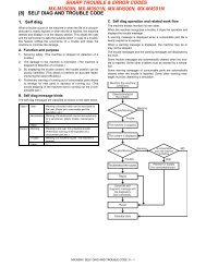
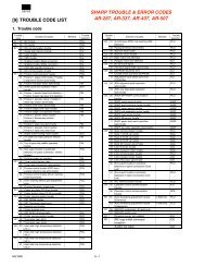
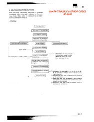
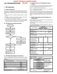
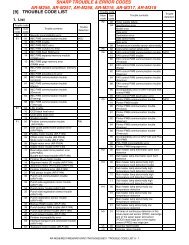
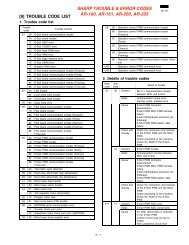

![[10] TEST COMMAND, TROUBLE CODES - OlsonBros](https://img.yumpu.com/18824764/1/190x245/10-test-command-trouble-codes-olsonbros.jpg?quality=85)