construction of a model demonstrating neural pathways and reflex arcs
construction of a model demonstrating neural pathways and reflex arcs
construction of a model demonstrating neural pathways and reflex arcs

Create successful ePaper yourself
Turn your PDF publications into a flip-book with our unique Google optimized e-Paper software.
double-wire connector<br />
from the skin.<br />
INNOVATIONS A N D I D E A S<br />
remaining wire to the<br />
left side <strong>of</strong> the bulb<br />
<strong>of</strong> the S - 2 unit .<br />
end to the left side <strong>of</strong><br />
the bulb <strong>of</strong> the S -1 unit.<br />
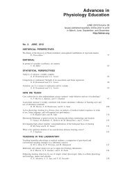
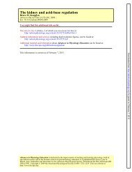
FIG. 17.<br />
Double-wire connector illustrated refers to the sensory neuron units<br />
described in the instructions (Part 2, c <strong>and</strong> D). The wires are crimped<br />
together at A. Shorter wire (30 cm) will connect to left side <strong>of</strong> S-2 unit (B)<br />
<strong>and</strong> longer wire (35 cm) will connect to left side <strong>of</strong> S-l unit (C). There is<br />
another sensory neuron unit that needs to be attached in the same<br />
manner. However, the wire endings will connect to the right side <strong>of</strong> S-l<br />
<strong>and</strong> S-2 units.<br />
represents the sensory neuron<br />
E. Place the 55-cm pieces <strong>of</strong> wire (sensory), the<br />
21-cm pieces <strong>of</strong> wire (motor), the lo-cm pieces <strong>of</strong><br />
wire (interneuron), <strong>and</strong> the double-wire connector<br />
(sensory) in a bag. Label the bag POLYSYNAPTIC<br />
MODEL.<br />
Part 4: <strong>neural</strong>pathway diagrams. Each <strong>neural</strong> path-<br />
way diagram consists <strong>of</strong> four 8 X 1 l-in. pages that<br />
serve as maps for the students to follow when<br />
constructing their own <strong>model</strong>.3 Make enough copies<br />
<strong>of</strong> each pathway so that each lab group has a complete<br />
set for the patellar tendon <strong>reflex</strong> <strong>and</strong> the polysynaptic<br />
withdrawal <strong>reflex</strong> upon painful stimulus <strong>model</strong>s (Figs.<br />
18 <strong>and</strong> 19).<br />
3 To request a master copy <strong>of</strong> the <strong>reflex</strong> <strong>pathways</strong> for<br />
duplication purposes, write to authors at NEOUCOM, 4209<br />
State Route 44, PO Box 95, Rootstown, OH 44272-0095 or fax<br />
(216) 325-2524.<br />
Part 5: student lab packets. Each student or group <strong>of</strong><br />
students will need a packet containing the following<br />
items to assemble the <strong>model</strong>s: four synaptic junctions<br />
(light/lamp <strong>and</strong> switch connected together), one low-<br />
voltage buzzer, one low-voltage motor, four AA batter-<br />
ies with holder, one monosynaptic wire packet in<br />
large plastic Ziploc bag, one polysynaptic wire packet<br />
in large plastic Ziploc bag.<br />
TIPS FOR TEACHERS<br />
Options<br />
We have presented two options for classroom presen-<br />
tation <strong>of</strong> the laboratory exercise. These two options<br />
are only suggestions, <strong>and</strong> individual teachers may have<br />
other ideas for the presentation <strong>of</strong> this exercise.<br />
I. Interactive demonstration (one class period). The<br />
laboratory would consist <strong>of</strong> <strong>demonstrating</strong> the <strong>model</strong><br />
that has been constructed before the students start the<br />
lab. With this option, four students can work with one<br />
<strong>model</strong>.<br />
VOLUME 16 : NUMBER 1 - ADVANCES IN PHYSIOLOGY EDUCATION - DECEMBER 1996<br />
S33