Panasonic Air Conditioner - LMG
Panasonic Air Conditioner - LMG
Panasonic Air Conditioner - LMG

Create successful ePaper yourself
Turn your PDF publications into a flip-book with our unique Google optimized e-Paper software.
4. Close the Low side valve of the charging set and turn off the vacuum pump. Make sure that the needle in the gauge does not<br />
move after approximately five minutes.<br />
Note: BE SURE TO TAKE THIS PROCEDURE IN ORDER TO AVOID REFRIGERANT GAS LEAKAGE.<br />
5. Disconnect the charging hose from the vacuum pump and from the service port of the 3-way valve.<br />
6. Tighten the service port caps of the 3-way valve at a torque of 18 N•m with a torque wrench.<br />
7. Remove the valve caps of both of the 2-way valve and 3-way valve. Position both of the valves to “OPEN” using a hexagonal<br />
wrench (4 mm).<br />
8. Mount valve caps onto the 2-way valve and the 3-way valve.<br />
• Be sure to check for gas leakage.<br />
• If gauge needle does not move from 0 cmHg (0 MPa) to -76 cmHg (-0.1 MPa), in step above take the following measure:<br />
- If the leak stops when the piping connections are tightened further, continue working from step .<br />
- If the leak does not stop when the connections are retightened, repair the location of leak.<br />
- Do not release refrigerant during piping work for installation and reinstallation.<br />
- Take care of the liquid refrigerant, it may cause frostbite.<br />
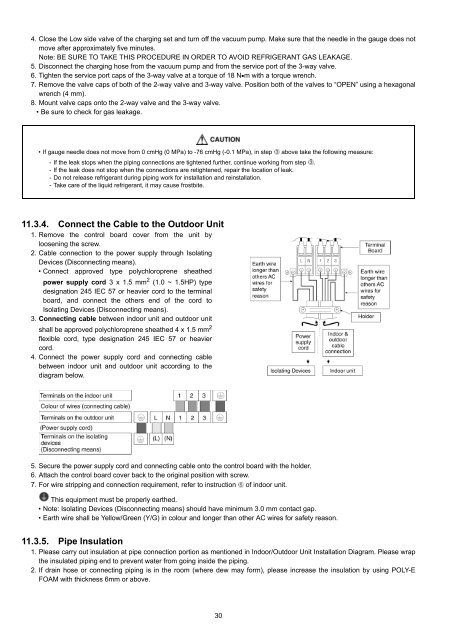
11.3.4. Connect the Cable to the Outdoor Unit<br />
1. Remove the control board cover from the unit by<br />
loosening the screw.<br />
2. Cable connection to the power supply through Isolating<br />
Devices (Disconnecting means).<br />
• Connect approved type polychloroprene sheathed<br />
power supply cord 3 x 1.5 mm 2 (1.0 ~ 1.5HP) type<br />
designation 245 IEC 57 or heavier cord to the terminal<br />
board, and connect the others end of the cord to<br />
Isolating Devices (Disconnecting means).<br />
3. Connecting cable between indoor unit and outdoor unit<br />
shall be approved polychloroprene sheathed 4 x 1.5 mm 2<br />
flexible cord, type designation 245 IEC 57 or heavier<br />
cord.<br />
4. Connect the power supply cord and connecting cable<br />
between indoor unit and outdoor unit according to the<br />
diagram below.<br />
5. Secure the power supply cord and connecting cable onto the control board with the holder.<br />
6. Attach the control board cover back to the original position with screw.<br />
7. For wire stripping and connection requirement, refer to instruction of indoor unit.<br />
This equipment must be properly earthed.<br />
• Note: Isolating Devices (Disconnecting means) should have minimum 3.0 mm contact gap.<br />
• Earth wire shall be Yellow/Green (Y/G) in colour and longer than other AC wires for safety reason.<br />
11.3.5. Pipe Insulation<br />
1. Please carry out insulation at pipe connection portion as mentioned in Indoor/Outdoor Unit Installation Diagram. Please wrap<br />
the insulated piping end to prevent water from going inside the piping.<br />
2. If drain hose or connecting piping is in the room (where dew may form), please increase the insulation by using POLY-E<br />
FOAM with thickness 6mm or above.<br />
30