DIamond TII Reservoir B - Clarkson Laboratory and Supply
DIamond TII Reservoir B - Clarkson Laboratory and Supply
DIamond TII Reservoir B - Clarkson Laboratory and Supply

Create successful ePaper yourself
Turn your PDF publications into a flip-book with our unique Google optimized e-Paper software.
Barnstead <strong>DIamond</strong> <strong>TII</strong><br />
Storage <strong>Reservoir</strong><br />
OPERATION MANUAL<br />
AND PARTS LIST<br />
30 L Storage <strong>Reservoir</strong>s<br />
D14061<br />
D14062<br />
D14063<br />
D14064<br />
60 L Storage <strong>Reservoir</strong>s<br />
D14071<br />
D14072<br />
D14073<br />
D14074<br />
LT1406X3 • 1/6/10 Serial Number _____________________________
Table of Contents<br />
Safety Information ..............................................................................................................................................3<br />
Warnings ......................................................................................................................................................3<br />
Introduction..........................................................................................................................................................4<br />
General Usage..............................................................................................................................................4<br />
Specifications ......................................................................................................................................................5<br />
<strong>Reservoir</strong> Dimensions ..................................................................................................................................5<br />
Environmental Conditions ............................................................................................................................5<br />
Declaration of Conformity ............................................................................................................................5<br />
Installation ..........................................................................................................................................................6<br />
Unpacking ....................................................................................................................................................6<br />
Choosing a Site ............................................................................................................................................7<br />
Water Connection Details ............................................................................................................................8<br />
Push-to-Connect Fitting Tubing Installation ..........................................................................................8<br />
Push-to-Connect Fitting Tubing Removal ..............................................................................................8<br />
Tubing Adapter Fittings ................................................................................................................................9<br />
Quick Disconnect Fittings ..........................................................................................................................10<br />
Bench Mounting ..........................................................................................................................................11<br />
Wall Mounting ............................................................................................................................................11<br />
Operation Connections ..............................................................................................................................12<br />
Ventgard Installation ..................................................................................................................................13<br />
Overflow Tubing..........................................................................................................................................13<br />
Optional UV Lamp Installation ....................................................................................................................13<br />
Optional Distribution Pump ........................................................................................................................14<br />
Maintenance <strong>and</strong> Servicing ..............................................................................................................................16<br />
General Cleaning Instructions ....................................................................................................................16<br />
<strong>Reservoir</strong> Sanitization ................................................................................................................................16<br />
Ventgard Filter Replacement ......................................................................................................................16<br />
Draining the <strong>Reservoir</strong> ................................................................................................................................16<br />
Wiring Diagram..................................................................................................................................................17<br />
Parts List ..........................................................................................................................................................18<br />
Consumables..............................................................................................................................................18<br />
General Maintenance Parts........................................................................................................................18<br />
Ordering Procedures ........................................................................................................................................19<br />
One Year Limited Warranty ..............................................................................................................................20<br />
Figures<br />
Figure 1: <strong>DIamond</strong> <strong>TII</strong> Storage <strong>Reservoir</strong>–Front View (60L) ............................................................................4<br />
Figure 2: <strong>DIamond</strong> <strong>TII</strong> Storage <strong>Reservoir</strong>–Rear View (60L)..............................................................................4<br />
Figure 3: Complete System Setup (Typical) ......................................................................................................7<br />
Figure 4: Tubing Installation ..............................................................................................................................8<br />
Figure 5: Tubing Removal..................................................................................................................................8<br />
Figure 6: Typical Polypropylene Tubing Adapter Installation ............................................................................9<br />
Figure 7: Quick Disconnect..............................................................................................................................10<br />
Figure 8: Water <strong>and</strong> Electrical Connections on <strong>DIamond</strong> <strong>TII</strong> ..........................................................................12<br />
Figure 9: Water Connections on <strong>Reservoir</strong>......................................................................................................13<br />
Figure 10: UV Lamp Installation ......................................................................................................................13<br />
Figure 11: Distribution Loop Connections ........................................................................................................15<br />
2
Warning<br />
Warnings alert you to a possibility of<br />
personal injury.<br />
Caution<br />
Cautions alert you to a possibility of<br />
damage to the equipment.<br />
Note<br />
Notes alert you to pertinent facts <strong>and</strong><br />
conditions.<br />
Safety Information<br />
Your Thermo Scientific Barnstead <strong>DIamond</strong> <strong>TII</strong> Storage<br />
<strong>Reservoir</strong> has been designed with function, reliability, <strong>and</strong><br />
safety in mind. It is your responsibility to install it in conformance<br />
with local electrical codes. For safe operation,<br />
please pay attention to the alert boxes throughout the<br />
manual.<br />
This manual contains important operating <strong>and</strong> safety<br />
information. You must carefully read <strong>and</strong> underst<strong>and</strong> the<br />
contents of this manual prior to using this equipment.<br />
Water purification technology employs one or more of the<br />
following: chemicals, electrical devices, mercury vapor<br />
lamps, steam <strong>and</strong> heated vessels. Care should be taken<br />
when installing, operating or servicing Barnstead products.<br />
Warnings<br />
To avoid electrical shock:<br />
1. Do not locate the <strong>DIamond</strong> <strong>TII</strong> Storage<br />
<strong>Reservoir</strong> directly over unprotected equipment<br />
that requires electrical service. Routine maintenance<br />
of this unit may involve water spillage<br />
<strong>and</strong> subsequent electrical shock hazard if improperly<br />
located.<br />
To avoid personal injury:<br />
1. Ensure all piping connections are tight to avoid<br />
leakage of chemicals.<br />
2. Ensure adequate ventilation when using chemicals<br />
for cleaning.<br />
3. Follow carefully the manufactures’ safety<br />
instructions on labels of chemical containers<br />
<strong>and</strong> Material Safety Data Sheets (M.S.D.S).<br />
4. Refer servicing to qualified personnel.<br />
3
Introduction<br />
4<br />
Draw Off<br />
Valve<br />
Figure 1: <strong>DIamond</strong> <strong>TII</strong> Storage <strong>Reservoir</strong><br />
Front View (60L)<br />
Top<br />
Mounting Bracket<br />
Bottom<br />
Mounting Bracket<br />
<strong>Reservoir</strong><br />
Float Cable<br />
UV Lamp<br />
Housing cap<br />
Product<br />
Inlet/Outlet<br />
Manifold<br />
Ventgard<br />
Filter<br />
Overflow<br />
Tube<br />
AC Power<br />
Entry<br />
<strong>DIamond</strong> Type II<br />
Interface Connector<br />
Check<br />
Valve<br />
Level-Sensing<br />
Floats<br />
Figure 2: <strong>DIamond</strong> <strong>TII</strong> Storage <strong>Reservoir</strong> Rear View (60L)<br />
Congratulations on your purchase of a Thermo Scientific<br />
Barnstead <strong>DIamond</strong> <strong>TII</strong> Storage <strong>Reservoir</strong> for your<br />
<strong>DIamond</strong> <strong>TII</strong>. This manual contains the information you<br />
will need to install, operate <strong>and</strong> maintain this storage<br />
reservoir. It is designed for direct connection to<br />
Barnstead’s <strong>DIamond</strong> <strong>TII</strong> System.<br />
Introduction<br />
Please read the instructions carefully to ensure that you<br />
receive maximum benefit from your <strong>DIamond</strong> <strong>TII</strong> Storage<br />
<strong>Reservoir</strong>. Please fill out <strong>and</strong> return the enclosed warranty<br />
registration card, assuring you of proper warranty coverage.<br />
Should you have questions after reading the<br />
entire manual, contact your laboratory supply dealer or<br />
Customer Service at 1-866-984-3766.<br />
General Usage<br />
This product is to be used for storing Type II product<br />
water. Sanitization/cleaning agents must be used in compliance<br />
with instructions in this manual. Do not use this<br />
product for anything other than its intended usage. If the<br />
equipment is used in a manner not specified by the manufacturer,<br />
the protection provided by the equipment may<br />
be impaired.
<strong>Reservoir</strong> Dimensions<br />
30L Storage <strong>Reservoir</strong><br />
D14061, D14062, D14063, D14064: 16.3” W x 17.4” D x 31.1” H (41.4 x 44.1 x 79.0 cm)<br />
Operating Weight: 110 lbs. (49.9 kg)<br />
60L Storage <strong>Reservoir</strong><br />
D14071, D14072, D14073, D14074: 16.3” W x 17.4” D x 41.0” H (41.4 x 44.1 x 104.1 cm)<br />
Operating Weight: 180 lbs. (81.6 kg)<br />
Environmental Conditions<br />
Operating: 17°C - 27°C; 20% - 80% relative humidity, non-condensing. Installation Category II<br />
(over-voltage) in accordance with IEC 664. Pollution Degree 2 in accordance with IEC 664.<br />
Altitude limit: 2,000 meters.<br />
Storage: -25°C - 65°C; 10% - 85% relative humidity.<br />
Declaration of Conformity<br />
We hereby declare under our sole responsibility that this product conforms with the technical requirements of<br />
the following st<strong>and</strong>ards:<br />
EMC: EN 61000-3-2 Limits for Harmonic Current Emissions<br />
EN 61000-3-3 Limits for Voltage Fluctuations <strong>and</strong> Flicker<br />
EN 61326-1 Electrical Equipment for Measurement, Control <strong>and</strong> <strong>Laboratory</strong> Use -<br />
EMC Requirements; Part 1: General Requirements<br />
Safety: EN61010-1 Safety Requirements for Electrical Equipment for Measurement, Control, <strong>and</strong><br />
<strong>Laboratory</strong> use; Part I: General Requirements<br />
per the provisions of the Low Voltage Directive 73/23/EEC, as amended by 93/68/EEC.<br />
The authorized representative located within the European Community is:<br />
Thermo Fisher Scientific<br />
Electrothermal House<br />
Unit 12A<br />
Purdeys Industrial Estate<br />
Purdeys Way<br />
Rochford, Essex SS4 1ND<br />
United Kingdom<br />
Tel: +44(0)1702 303350<br />
Copies of the Declaration of Conformity are available upon request.<br />
Specifications<br />
5
Installation<br />
6<br />
Caution<br />
Unpack the storage reservoir shipping<br />
box carefully.<br />
Note<br />
There will be no tubing other than the<br />
overflow tubing assembly included.<br />
Feed <strong>and</strong> product tubing is included<br />
with the <strong>DIamond</strong> <strong>TII</strong>.<br />
Unpacking<br />
1. Remove all protective inserts from the shipping<br />
box.<br />
2. If the reservoir is equipped with a distribution<br />
pump option, unpack the distribution loop tubing<br />
coil (TU1406X1).<br />
3. If the reservoir is equipped with a UV lamp<br />
option, unpack the UV lamp (LMX31).<br />
4. Remove the accessory bag from the shipping<br />
carton. This will include the following items.<br />
• For all models: Operation manual, interface<br />
cable, wall bracket<br />
• For all models except D14061 <strong>and</strong> D14071:<br />
American cordset <strong>and</strong> European cordset.<br />
• For models D14061, D14062, D14071 <strong>and</strong><br />
D14072: 1/2” male NPT x 1/4” female NPT<br />
adapter.<br />
• For models D14063, D14064, D14073 <strong>and</strong><br />
D14074: (2) plumbing tees, flow restrictor, 1/4”<br />
NPT pipe nipple, 1/2” NPT <strong>and</strong> 1/2” tube<br />
adapter, <strong>and</strong> 1/4” NPT x 1/2” tube adapter.<br />
5. Remove the storage reservoir from the shipping<br />
box <strong>and</strong> place on a bench.
Warning<br />
Do not locate the <strong>DIamond</strong> <strong>TII</strong> Storage<br />
<strong>Reservoir</strong> directly over equipment that<br />
requires electrical service. Routine<br />
maintenance of this unit may involve<br />
water spillage <strong>and</strong> subsequent electrical<br />
shock hazard if improperly located.<br />
Do not use in the presence of flammable<br />
or combustible materials; fire or<br />
explosion may result. The device contains<br />
components which may ignite<br />
such materials.<br />
Type II Water<br />
Manual<br />
Draw-Off<br />
<strong>Reservoir</strong> Interface Cable<br />
Type II Water<br />
Outlet<br />
Figure 3: Complete System Setup (Typical)<br />
Purified Water<br />
Recirculation<br />
Water<br />
INSTALLATION<br />
Choosing a Site<br />
The storage reservoir must be properly oriented in relationship<br />
to the <strong>DIamond</strong> <strong>TII</strong> to provide for fully automatic<br />
operation. The storage reservoir should be located no<br />
more than 6 feet <strong>and</strong> no less than 8 inches from the<br />
<strong>DIamond</strong> <strong>TII</strong>. The storage reservoir must be mounted so<br />
that the reservoir outlet is at the same level or higher than<br />
the inlet of the <strong>DIamond</strong> <strong>TII</strong>. Also, if the storage reservoir<br />
is to be used as a source water to a NANOpure <strong>DIamond</strong><br />
or other water system <strong>and</strong> no distribution pump is used,<br />
the reservoir outlet must be at the same level or higher<br />
than the inlet to the NANOpure <strong>DIamond</strong> or other water<br />
system. Allow a minimum of 8 inches (20.3 cm) clearance<br />
on sides <strong>and</strong> 15 inches (38.1 cm) clearance above<br />
the unit for servicing. See Figure 3 for a typical system<br />
setup. If the storage reservoir has the distribution pump<br />
or UV lamp options, locate within 6.0 feet (15.2 cm) of an<br />
electrical outlet.<br />
Inlet<br />
Feed Water<br />
77°F(25°C)<br />
Drain<br />
Type II Water<br />
Manual or<br />
Automatic<br />
Draw-Off<br />
7
INSTALLATION<br />
8<br />
Figure 4<br />
Tubing Installation<br />
TYPICAL<br />
FITTING<br />
3/4"<br />
Insertion<br />
Length<br />
COLLET<br />
Figure 5<br />
Tubing Removal<br />
TUBE REMOVAL TOOL<br />
TUBING<br />
Note<br />
For easier insertion, wet the end of<br />
the tubing with water.<br />
Note<br />
Figure 4 <strong>and</strong> 5 will be used at the<br />
connection to the atmospheric drain.<br />
TUBING<br />
COLLET<br />
TYPICAL FITTING<br />
Water Connection Details<br />
Push-to-Connect Fitting Tubing<br />
Installation (Refer to Fig. 4)<br />
The following instructions will apply when you need to<br />
attach a piece of tubing to your <strong>DIamond</strong> <strong>TII</strong> during installation,<br />
unless otherwise noted in the installation instructions.<br />
To make tubing connections:<br />
1. Make sure the tubing is cut off reasonably<br />
square <strong>and</strong> that no plastic burrs or ridges<br />
are present.<br />
2. Mark from end of tube an insertion length of 3/4”.<br />
3. Wet the tube end with water <strong>and</strong> insert the tube<br />
straight into the fitting until it bottoms out on the<br />
interior shoulder <strong>and</strong> the insertion mark is no<br />
longer visible.<br />
Push-to-Connect Fitting Tubing Removal<br />
(Refer to Fig. 5)<br />
1. Using the tool provided (AYX23), push the collet<br />
toward the body while pulling on the tubing to<br />
release the tube.<br />
PLACE REMOVAL TOOL UP AGAINST<br />
COLLET AND PUSH FORWARD WHILE<br />
SIMULTANEOUSLY PULLING THE TUBE<br />
BACK<br />
PULL TUBING
Caution<br />
Do not use a wrench to tighten connections<br />
made with tubing adapters.<br />
Watertight connections can be made<br />
by h<strong>and</strong>.<br />
Figure 6: Typical Polypropylene Tubing Adapter Installation<br />
INSTALLATION<br />
Tubing Adapter Fittings<br />
1. Completely disassemble the fitting. Refer to<br />
Figure 6 to familiarize yourself with the names<br />
of the component parts.<br />
2. Make sure the tubing is cut off reasonably<br />
square <strong>and</strong> that no plastic burrs or ridges are<br />
present.<br />
3. Place the grab ring <strong>and</strong> backup ring in the hex<br />
nut in the order <strong>and</strong> orientation shown in<br />
Figure 6. Thread the nut onto the adapter. DO<br />
NOT use the o-ring at this time.<br />
4. Push the tubing through the nut until it bottoms<br />
out in the adapter.<br />
5. Remove the adapter nut <strong>and</strong> tubing. Place the<br />
o-ring over the tubing. Be careful not to push<br />
the backup ring or grab ring further back on the<br />
tubing when installing the o-ring.<br />
6. Install the hex nut on the adapter <strong>and</strong> h<strong>and</strong><br />
tighten.<br />
9
INSTALLATION<br />
10<br />
Note<br />
The quick disconnect fittings contain<br />
valves <strong>and</strong> if not properly inserted<br />
water will not flow.<br />
Coupling Body<br />
Figure 7: Quick Disconnect<br />
Push down on thumbpad<br />
to release coupling insert<br />
Quick Disconnect Fittings<br />
These fittings are found in the tubing that connects the<br />
“TO UNIT” reservoir outlet to the “FROM TANK” system<br />
inlet. (See Fig. 7)<br />
To insert the inlet tubing:<br />
1. Press on the metal thumbpad on the coupling<br />
body to ensure the fitting is open.<br />
2. Wet the o-ring on the coupling insert <strong>and</strong> push<br />
into the coupling body until you hear a click.<br />
Gently pull on the tubing to ensure it is secure.<br />
3. To remove, press the metal thumbpad to release<br />
<strong>and</strong> pull coupling insert out.<br />
Coupling Insert
Note<br />
The outlet of a gravity feed storage<br />
reservoir must be above or at the<br />
same level as the inlet of the <strong>DIamond</strong><br />
<strong>TII</strong> or other water system.<br />
Warning<br />
Do not locate the <strong>DIamond</strong> <strong>TII</strong> Storage<br />
<strong>Reservoir</strong> directly over equipment that<br />
requires electrical service. Routine<br />
maintenance of this unit may involve<br />
water spillage <strong>and</strong> subsequent electrical<br />
shock hazard if improperly located.<br />
Do not use in the presence of flammable<br />
or combustible materials; fire or<br />
explosion may result. The device contains<br />
components which may ignite<br />
such materials.<br />
Caution<br />
Wall composition, condition <strong>and</strong><br />
construction as well as fastener type<br />
must be considered when mounting<br />
this unit. The mounting surface <strong>and</strong><br />
fasteners selected must be capable of<br />
supporting a minimum of 200 lbs. (91<br />
kg). Inadequate support <strong>and</strong>/or fasteners<br />
may result in damage to mounting<br />
surface <strong>and</strong>/or equipment. If you are<br />
unsure of mounting surface<br />
composition, condition <strong>and</strong> construction<br />
or correct fasteners, consult your<br />
building maintenance group or<br />
contractor.<br />
Bench Mounting<br />
If a 30L reservoir is to be located on a bench, no mounting<br />
brackets are necessary. Simply set the reservoir on<br />
the bench. If a 60L reservoir is to be located on a bench,<br />
the top mounting bracket must be securely attached,<br />
using customer-supplied fasteners, to a rigid structure for<br />
stability.<br />
Wall Mounting<br />
Install the <strong>DIamond</strong> <strong>TII</strong> Storage <strong>Reservoir</strong> on a wall in a<br />
convenient location that is accessible to an atmospherically<br />
vented drain.<br />
1. Locate the lower wall bracket packed separately<br />
from the unit.<br />
2. Using the lower wall bracket as a template,<br />
locate <strong>and</strong> drill the mounting holes in the wall.<br />
Use a minimum of four customer-supplied fasteners<br />
for the bottom bracket.<br />
3. Set reservoir on lower bracket.<br />
INSTALLATION<br />
4. Fasten top mounting bracket (shipped attached)<br />
to the wall using a minimum of two customersupplied<br />
fasteners.<br />
11
INSTALLATION<br />
12<br />
Note<br />
See Figure 3 for complete system<br />
setup.<br />
REMOTE DISPLAY<br />
TANK INTERFACE<br />
RS232<br />
GENERAL I/O<br />
TANK FLOATS<br />
ACCU. DISPENSE<br />
CARBOY FLOAT<br />
NIST CAL MODULE<br />
PUMP INTERLOCK<br />
REMOTE 1 REMOTE 2<br />
FROM TANK TO TANK<br />
DRAIN FEEDWATER INLET<br />
100 PSI MAX<br />
120°F MAX<br />
Figure 8: Water <strong>and</strong> Electrical Connections on<br />
<strong>DIamond</strong> <strong>TII</strong><br />
Operation Connections<br />
Whether mounted on a bench or wall, the front of your<br />
<strong>DIamond</strong> <strong>TII</strong> Storage <strong>Reservoir</strong> should now be facing you.<br />
1. Two electrical cables are required to connect<br />
the water system to the storage reservoir. The<br />
first is hardwired to the reservoir <strong>and</strong> attaches<br />
to the “Tank Floats” connection on the<br />
<strong>DIamond</strong> <strong>TII</strong>. The other cable is reversible <strong>and</strong><br />
connects between the mini-din (circular) connector<br />
on the left side of the reservoir base<br />
<strong>and</strong> the “Tank Interface” connection on the<br />
<strong>DIamond</strong> <strong>TII</strong>.<br />
2. Two tubes are included with the <strong>DIamond</strong> <strong>TII</strong><br />
to connect the water system to the storage<br />
reservoir. They connect from the “TO UNIT”<br />
<strong>and</strong> “FROM UNIT” connections on the reservoir<br />
manifold to the “FROM TANK” <strong>and</strong> “TO<br />
TANK” connections on the system manifold.<br />
See Figure 8. IMPORTANT: The tube with the<br />
integral quick disconnect must be connected<br />
between the “TO UNIT” <strong>and</strong> “FROM TANK”<br />
ports.<br />
3. If an optional UV lamp or distribution pump has<br />
been purchased, determine which power cord<br />
you need <strong>and</strong> attach the power cord to the<br />
power entry module <strong>and</strong> the wall outlet.<br />
4. If a distribution pump has not been purchased,<br />
the 1/2” NPT port in the product inlet/outlet<br />
manifold (See Figure 1) labeled “LOOP OUT”<br />
can be used as a gravity feed outlet. Use the<br />
included 1/2” NPT x 1/4” NPT adapter to connect<br />
to the NANOpure <strong>DIamond</strong> inlet tubing, or<br />
use the customer-supplied fittings <strong>and</strong> tubing<br />
to connect this outlet to the unit to be fed.<br />
Make sure the reservoir outlet is at the same<br />
level or above the inlet of the unit being fed.
LOOP OUT TO UNIT LOOP IN FROM UNIT<br />
Figure 9: Water Connections on <strong>Reservoir</strong><br />
UV LAMP<br />
COVER<br />
CONNECTOR<br />
HOLD-DOWN<br />
CLIP<br />
UV LAMP<br />
PLASTIC NUT<br />
Figure 10: UV Lamp Installation<br />
Ventgard ®<br />
Installation<br />
INSTALLATION<br />
Unscrew the cap on the Ventgard assembly <strong>and</strong> remove<br />
gasket, remove Ventgard filter from wrapper, insert into<br />
cap, replace gasket <strong>and</strong> h<strong>and</strong> tighten cap.<br />
Following Ventgard installation, the “<strong>Reservoir</strong> Vent Timer”<br />
must be reset on the <strong>DIamond</strong> <strong>TII</strong>. See the <strong>DIamond</strong> <strong>TII</strong><br />
manual to reset the “<strong>Reservoir</strong> Vent Timer.”<br />
Overflow Tubing<br />
Route the storage reservoir overflow tubing to an atmospherically<br />
vented drain. VERY IMPORTANT: For correct<br />
operation, the overflow tubing must run downhill<br />
along its entire length. There can be no uphill sections<br />
or kinks in the tubing.<br />
Optional UV Lamp Installation<br />
Locate the UV lamp housing cover at the top of the<br />
<strong>DIamond</strong> <strong>TII</strong> reservoir. See Figure 10. Install the UV lamp<br />
as follows:<br />
1. Disconnect the power cord from the unit.<br />
2. Remove the UV lamp housing cover on top of<br />
the reservoir by rotating the two hold-down clips.<br />
The UV lamp will be installed vertically.<br />
3. Remove the UV lamp from its packaging. DO<br />
NOT TOUCH THE GLASS PORTION OF THE<br />
LAMP! It is recommended that lint-free gloves be<br />
worn when h<strong>and</strong>ling the lamp. The glass portion<br />
must be free of fingerprints, perspiration, etc.<br />
Even a light coating of perspiration will reduce<br />
the effectiveness of the lamp. If the glass portion<br />
of the lamp is touched, clean it with a damp, lintfree<br />
cloth <strong>and</strong> use isopropyl alcohol as required.<br />
4. Loosen the plastic nut on the reservoir cap just<br />
until the UV lamp will slide through. Take care<br />
not to drop the lamp through the fitting as this<br />
can result in damage to the lamp. Insert the<br />
lamp through the nut slowly until it bottoms out<br />
in the fitting. The top of the lamp should be<br />
approximately flush with the top of the nut.<br />
13
INSTALLATION<br />
14<br />
Caution<br />
To prevent damage to the UV lamp,<br />
h<strong>and</strong> tighten the nut only. Do not<br />
overtighten.<br />
Note<br />
It is suggested that PTFE tape be<br />
applied to the NPT threads to ensure<br />
a tight seal.<br />
® Fast & Tite is a registered trademark of D & G<br />
Plastics Co.<br />
5. H<strong>and</strong> tighten the nut until snug <strong>and</strong> connect the<br />
UV lamp to the connector inside the UV lamp<br />
housing cover. Replace the cover. Make sure to<br />
rotate the plastic hold-down clips back over the<br />
cover flange.<br />
6. As a factory default, the UV lamp will be on for<br />
10 minutes per day to control bacterial growth.<br />
To change this setting, use the <strong>DIamond</strong> <strong>TII</strong><br />
menu screen. Press "Menu" - Use arrows to<br />
select "<strong>Reservoir</strong> Options" - use arrows to select<br />
"UV Lamp Timer" - adjust setting using the<br />
arrow keys, <strong>and</strong> press "OK" to accept.<br />
Optional Distribution Pump<br />
An optional distribution pump is located in the storage<br />
reservoir base. The system allows the user to transport<br />
Type II water to remote locations. It automatically maintains<br />
a 40 psi (2.7 bar) pressure <strong>and</strong> will distribute 4.5<br />
liters per minute at 40 psi. The pump will adjust its output<br />
to meet changing water dem<strong>and</strong>. 50 feet of tubing <strong>and</strong><br />
adapters are provided for the distribution loop.<br />
To connect distribution pump to water system:<br />
1. Attach tubing to Fast & Tite ® fitting on <strong>DIamond</strong><br />
<strong>TII</strong> Storage <strong>Reservoir</strong>. See Figure 8 for connection<br />
details.<br />
2. Route tubing appropriately <strong>and</strong> place supplied<br />
Fast & Tite tee fitting at desired draw-off location.<br />
Attach customer supplied fittings <strong>and</strong> tubing<br />
to the NPT threads on the tee fitting, <strong>and</strong> route<br />
to system to be fed. It is recommended that a<br />
shut-off valve be placed in the tubing between<br />
the tee fitting <strong>and</strong> system to be fed to prevent<br />
bleach water from entering the fed unit during a<br />
sanitization cycle.<br />
3. Continue distribution loop back to storage reservoir<br />
<strong>and</strong> connect to the flow restrictor <strong>and</strong> then<br />
to the “LOOP IN” port. See Figure 11.
"LOOP OUT"<br />
REMOVE<br />
EXISTING<br />
PLUGS<br />
"LOOP IN"<br />
1/2" O.D.<br />
TUBING<br />
STRAIGHT<br />
FITTING<br />
TEE FITTING<br />
NIPPLE<br />
FLOW<br />
1/2" O.D.<br />
TUBING<br />
The distribution pump operation is controlled through the<br />
<strong>DIamond</strong> <strong>TII</strong> menu screen. Press “Menu,” use arrows to<br />
select “<strong>Reservoir</strong> Options,” use arrows to select “Dist.<br />
Pump,” <strong>and</strong> select “ON” or “OFF”. When “ON” is selected,<br />
the distribution pump will operate continuously whenever<br />
the <strong>DIamond</strong> <strong>TII</strong> is left in RUN or STANDBY modes,<br />
<strong>and</strong> will automatically turn off when the <strong>DIamond</strong> <strong>TII</strong> is<br />
placed in IDLE mode.<br />
FLOW<br />
RESTRICTOR<br />
(NOTE ARROW POSITION)<br />
STRAIGHT<br />
FITTING<br />
INSTALLATION<br />
Figure 11: Distribution Loop Connections<br />
15
Maintenance <strong>and</strong> Servicing<br />
16<br />
Warning<br />
Avoid splashing disinfecting solutions<br />
on clothing or skin. Ensure all piping<br />
connections are tight to avoid leakage<br />
of chemicals. Ensure adequate ventilation.<br />
Follow carefully the manufacturer’s<br />
safety instructions on labels of<br />
disinfectant containers <strong>and</strong> Material<br />
Safety Data Sheets (M.S.D.S.)<br />
General Cleaning Instructions<br />
Wipe exterior surfaces with a dampened cloth containing<br />
a mild soap solution.<br />
<strong>Reservoir</strong> Sanitization<br />
The frequency of cleaning depends on the rate <strong>and</strong><br />
amount of contamination or build-up in the reservoir.<br />
The sanitization procedure is automated <strong>and</strong> can be<br />
accessed through the menus on the <strong>DIamond</strong> <strong>TII</strong> display.<br />
See the “System Sanitization Procedure” in the<br />
<strong>DIamond</strong> <strong>TII</strong> Operation Manual.<br />
Ventgard ®<br />
Filter Replacement<br />
The Ventgard filter assembly should be replaced every 6<br />
months or after 1,000 gallons have been drawn from the<br />
storage reservoir. A Ventgard filter assembly may be<br />
stored in a cool, dry place almost indefinitely, provided<br />
the plastic bag has not been opened. Refer to Ventgard<br />
Installation for replacement instructions.<br />
Draining the <strong>Reservoir</strong><br />
It will be necessary to drain the reservoir to complete<br />
some procedures or for general maintenance <strong>and</strong> cleaning.<br />
To drain the reservoir, follow these steps:<br />
1. Disconnect the quick disconnect fitting in the<br />
“TO UNIT-FROM TANK” tube. See Figure 7.<br />
2. Remove the tubing from the “FROM TANK”<br />
connection on the system manifold.<br />
3. Route the removed tubing end to a suitable<br />
drain.<br />
4. Reconnect the quick disconnect fitting.<br />
5. This procedure can be expedited by manually<br />
drawing water from the draw off valve on the<br />
front of the reservoir.
H<br />
J<br />
P6 (<br />
F2<br />
GRN<br />
REMOTE<br />
DISPLAY<br />
GND<br />
F3<br />
(2) FZX79<br />
(NEUTRAL)<br />
F4<br />
N<br />
W12<br />
2<br />
(LINE)<br />
TANK<br />
INTERFACE<br />
L<br />
(2) EMPTY PINS<br />
(6) EMPTY PINS<br />
T2<br />
W13<br />
PRINTER/<br />
COMPUTER/<br />
PROGRAMMING<br />
BLK<br />
RED<br />
BLK<br />
RED<br />
GENERAL I/O<br />
P5<br />
YEL<br />
W11<br />
GRN<br />
W9<br />
TANK FLOATS<br />
J55<br />
PWR COMM<br />
F5<br />
ACCU<br />
DISPENSE<br />
GND<br />
+24 vdc<br />
GND<br />
+24 vdc<br />
1<br />
1<br />
1<br />
TANK UV<br />
LAMP<br />
PUMP<br />
POWER<br />
W10<br />
PUMP<br />
CONTROL<br />
JMP3<br />
JMP1 JMP2<br />
24V<br />
24V<br />
+ -<br />
UV INTERLOCK<br />
NIST CAL<br />
MODULE<br />
J11<br />
E4<br />
RED<br />
WHT<br />
BLK<br />
RED<br />
BLK<br />
GRN, WHT<br />
PUMP<br />
INTERLOCK<br />
E<br />
H<br />
Wiring Diagram<br />
A2<br />
J<br />
LEFT SIDE<br />
CONNECTION<br />
DETAIL<br />
BLK<br />
BLU<br />
(TANK ELECTRONICS BOX)<br />
W14<br />
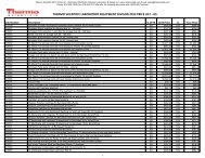
REF. DESCRIPTION<br />
D14031/ D14061 D14062 D14063 D14064 D14071 D14072 D14073 D14074<br />
D14041<br />
A1 ACCU-DISPENSE ASSEMBLY<br />
D13661 -<br />
-<br />
-<br />
-<br />
-<br />
-<br />
-<br />
-<br />
A2 DISPENSE OVERFLOW CUTOFF FLOAT<br />
AY1367X1 - - - -<br />
- -<br />
-<br />
-<br />
B2 TANK BALLAST ASSEMBLY<br />
- - TN1406X1 - TN1406X1 - TN1406X1 - TN1406X1<br />
E4 CALIBRATION GOLD CELL<br />
E1403X4 - - - -<br />
- -<br />
-<br />
-<br />
E5 CALIBRATION NIST MODULE<br />
E1403X5 - - - - - - - -<br />
F2 TANK FLOAT (TOP-NC)<br />
- SW1406X2 SW1406X2 SW1406X2 SW1406X2 SW1406X2 SW1406X2 SW1406X2<br />
JMP2 JMP3<br />
1<br />
2<br />
JMP1<br />
CONFIGURATION<br />
P5 BOARD<br />
F3 TANK FLOAT (MIDDLE-NO)<br />
- SW1406X2 SW1406X2 SW1406X2 SW1406X2<br />
SW1406X2<br />
F4 TANK FLOAT (LOW-NC)<br />
- SW1406X2 SW1406X2 SW1406X2 SW1406X2 SW1406X2 SW1406X2 SW1406X2<br />
TANK SIZE 30L<br />
PC1406X1/PC1406X2<br />
M<br />
F5 PUMP PROTECT FLOAT (NO)<br />
- SW1137X1 SW1137X1 SW1137X1 SW1137X1 SW1137X1 SW1137X1 SW1137X1 SW1137X1<br />
TANK SIZE 60L<br />
PC1406X1/PC1406X2<br />
1<br />
2<br />
1<br />
2<br />
UV OPTION<br />
PC1406X2<br />
1<br />
2<br />
PUMP OPTION<br />
PC1406X2<br />
1<br />
2<br />
3<br />
PUMP + UV OPTION<br />
PC1406X2<br />
L2 LAMP (TANK UV)<br />
- - LMX31 - LMX31<br />
- LMX31<br />
-<br />
LMX31<br />
M5 MAGNET FOR UV COVER ASSEMBLY<br />
-<br />
- SWX228 - SWX228 - SWX228 - SWX228<br />
P5 TANK CONTROL BOARD<br />
- PC1406X1 PC1406X2 PC1406X2 PC1406X2 PC1406X1<br />
PC1406X2 PC1406X2<br />
P6 DISTRIBUTION SMART PUMP ASSEMBLY<br />
-<br />
-<br />
- PU1406X1 PU1406X1<br />
-<br />
- PU1406X1 PU1406X1<br />
T2 POWER SUPPLY<br />
-<br />
-<br />
TNX129 TNX129 TNX129<br />
-<br />
TNX129 TNX129 TNX129<br />
W7 WIRE HARNESS<br />
WH1403X4 -<br />
- - - -<br />
- - -<br />
W8 WIRE HARNESS<br />
-<br />
- CRX111 CRX111 CRX111<br />
- CRX111 CRX111 CRX111<br />
W9 WIRE HARNESS<br />
- WH1406X6 WH1406X6 WH1406X6 WH1406X6 WH1406X6 WH1406X6 WH1406X6 WH1406X6<br />
W10 WIRE HARNESS<br />
-<br />
- SW1406X1 - SW1406X1 - SW1406X1 - SW1406X1<br />
W11 WIRE HARNESS<br />
-<br />
- WH1406X4 WH1406X4 WH1406X4 - WH1406X4 WH1406X4 WH1406X4<br />
W12 WIRE HARNESS<br />
-<br />
- WH1406X5 WH1406X5 WH1406X5 -<br />
WH1406X5<br />
W13 WIRE HARNESS<br />
-<br />
- WH1406X3 WH1406X3 WH1406X3 - WH1406X3 WH1406X3 WH1406X3<br />
W14 WIRE HARNESS<br />
-<br />
- WH1406X1 - WH1406X1 - WH1406X1 - WH1406X1<br />
W15 WIRE HARNESS<br />
-<br />
- WH1406X2 - WH1406X2 - WH1406X2 - WH1406X2<br />
17
Parts List<br />
18<br />
Consumables<br />
25001 Ventgard filter element<br />
LMX31 <strong>Reservoir</strong> UV Lamp<br />
General Maintenance Parts<br />
PMX134 Draw-off Valve<br />
PMX88 Tee Fitting for Distribution Loop<br />
PMX101 Flow Restrictor for Distribution Loop<br />
TU1406X1 1/2" OD Tubing for Distribution Loop (50 ft. length)<br />
PMX305 Overflow Check Valve<br />
SW1137X1 Bottom Float (Used only in bottom position)<br />
SW1406X2 Upper Float (Used in top three positions)<br />
CRX111 <strong>Reservoir</strong> Interface Cable<br />
WH1406X6 Float Cable<br />
CUX9 Quick Disconnect Coupling Insert<br />
CUX11 Quick Disconnect Coupling Body<br />
FZX79 Fuse, Power Entry (2 required)
Ordering Procedures<br />
Please refer to the Specification Plate for the complete<br />
model number, serial number, <strong>and</strong> series number when<br />
requesting service, replacement parts or in any correspondence<br />
concerning this unit.<br />
All parts listed herein may be ordered from the Thermo<br />
Scientific dealer from whom you purchased this unit or<br />
can be obtained promptly from the factory. When service<br />
or replacement parts are needed we ask that you check<br />
first with your dealer. If the dealer cannot h<strong>and</strong>le your<br />
request, then contact our Customer Service Department<br />
at 866-984-3766.<br />
Prior to returning any materials, please contact our<br />
Customer Service Department for a “Return Materials<br />
Authorization” number (RMA). Material returned without<br />
an RMA number will be refused.<br />
19
20<br />
One Year Limited Warranty<br />
This Thermo Scientific product is warranted to be free of defects in materials <strong>and</strong> workmanship for one (1)<br />
year from the first to occur of (i) the date the product is sold by the manufacturer or (ii) the date the product is<br />
purchased by the original retail customer (the “Commencement Date”). Except as expressly stated above, the<br />
MANUFACTURER MAKES NO OTHER WARRANTY, EXPRESSED OR IMPLIED, WITH RESPECT TO THE<br />
PRODUCTS AND EXPRESSLY DISCLAIMS ANY AND ALL WARRANTIES, INCLUDING BUT NOT LIMITED<br />
TO, WARRANTIES OF DESIGN, MERCHANT ABILITY AND FITNESS FOR A PARTICULAR PURPOSE.<br />
An authorized representative of the manufacturer must perform all warranty inspections. In the event of a<br />
defect covered by the warranty, we shall, as our sole obligation <strong>and</strong> exclusive remedy, provide free replacement<br />
parts to remedy the defective product. In addition, for products sold within the continental United States<br />
or Canada, the manufacturer shall provide free labor to repair the products with the replacement parts, but<br />
only for a period of ninety (90) days from the Commencement Date.<br />
The warranty provided hereunder shall be null <strong>and</strong> void <strong>and</strong> without further force or effect if there is any (i)<br />
repair made to the product by a party other than the manufacturer or its duly authorized service representative,<br />
(ii) misuse (including use inconsistent with written operating instructions for the product), mish<strong>and</strong>ling,<br />
contamination, overheating, modification or alteration of the product by any customer or third party or (iii) use<br />
of replacement parts that are obtained from a party who is not an authorized dealer of Thermo Scientific products.<br />
Heating elements, because of their susceptibility to overheating <strong>and</strong> contamination, must be returned to the<br />
factory <strong>and</strong> if, upon inspection, it is concluded that failure is due to factors other than excessive high temperature<br />
or contamination, the manufacturer will provide warranty replacement. As a condition to the return of any<br />
product, or any constituent part thereof, to the factory, it shall be sent prepaid <strong>and</strong> a prior written authorization<br />
from the manufacturer assigning a Return Materials Number to the product or part shall be obtained.<br />
IN NO EVENT SHALL THE MANUFACTURER BE LIABLE TO ANY PARTY FOR ANY DIRECT, INDIRECT,<br />
SPECIAL, INCIDENTAL, OR CONSEQUENTIAL DAMAGES, OR FOR ANY DAMAGES RESULTING FROM<br />
LOSS OF USE OR PROFITS, ANTICIPATED OR OTHERWISE, ARISING OUT OF OR IN CONNECTION<br />
WITH THE SALE, USE OR PERFORMANCE OF ANY PRODUCTS, WHETHER SUCH CLAIM IS BASED ON<br />
CONTRACT, TORT (INCLUDING NEGLIGENCE), ANY THEORY OF STRICT LIABILITY OR REGULATORY<br />
ACTION.<br />
For the name of the authorized Thermo Scientific product dealer nearest you or any additional information, contact us:<br />
308 Ridgefield Court, Ashville, NC, 28806 USA<br />
Phone: 1-866-984-3766<br />
Fax: 1-828-665-4071<br />
Web: www.thermo.com