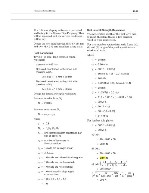
(no lateral bracing specified) = 3
(no lateral bracing specified) = 3
(no lateral bracing specified) = 3
Create successful ePaper yourself
Turn your PDF publications into a flip-book with our unique Google optimized e-Paper software.
Introduction to Wood Design<br />
38 × 184 mm sloping rafters are untreated<br />
and belong to the Spruce-Pine-Fir group. They<br />
will be seasoned and the service conditions<br />
will be dry.<br />
Design the heel joint between the 38 × 184 mm<br />
and two 38 × 235 mm members using nails.<br />
heel Connection<br />
Try 3in (76 mm) long common round<br />
wire nails<br />
diameter = 3.66 mm<br />
Required penetration in the head side<br />
member is 3d F.<br />
3 × 3.66 = 11 mm < 38 mm<br />
Required penetration in the point side<br />
member is 5d F.<br />
5 × 3.66 = 18 mm < 38 mm<br />
Design for <strong>lateral</strong> strength resistance<br />
Factored tensile force, N f<br />
N f = 2500 N<br />
Factored resistance, N r<br />
where<br />
N r = ϕN un F n sJ F<br />
ϕ = 0.8<br />
N u = n u(K D K SF K T)<br />
n u = unit <strong>lateral</strong> strength resistance per<br />
nail or spike, N<br />
n F = number of fasteners in<br />
the connection<br />
n s = 1 (nails are in single shear)<br />
J F = J eJ AJ BJ D<br />
J e = 1.0 (nails are driven into side grain)<br />
J A = 1.0 (nails are <strong>no</strong>t toe nailed)<br />
J B = 1.0 (nails are <strong>no</strong>t clinched)<br />
J D = 1.0 (<strong>no</strong>t used in diaphragm<br />
construction)<br />
J F = 1.0 × 1.0 × 1.0 × 1.0<br />
= 1.0<br />
11-63<br />
unit Lateral Strength Resistance<br />
The penetration depth of the nail is 76 mm<br />
(3 inch), therefore this is a two member<br />
wood to wood connection.<br />
For two-member connections, only Items (a),<br />
(b) and (d) to (g) of the yield equations are<br />
considered valid.<br />
where<br />
t 1 = 38 mm<br />
d F = 3.66 mm<br />
f 2 = 50G(1 – 0.01d F)<br />
= 50 × 0.42 × (1 – 0.01 × 3.66)<br />
= 20 MPa<br />
G = 0.42 (CSA O86, Table A. 10.1)<br />
t 2 = 38 mm<br />
f 3 = 110G 1.8 (1 – 0.01d F)<br />
= 110 × 0.42 1.8 × (1 – 0.01 × 3.66)<br />
= 22 MPa<br />
f y = 50(16 – d F)<br />
= 50 × (16 – 3.66)<br />
= 617 MPa<br />
For lumber side plates:<br />
f 1 = 50G(1 – 0.01d F)<br />
= 20 MPa<br />
(a) f1dFt1 = 20 × 3.66 × 38<br />
= 2814 N<br />
(b) f2dFt2 = 20 × 3.66 × 38<br />
= 2714 N<br />
(d) f 2 c<br />
1dF 1<br />
6 (f<br />
f3<br />
fy<br />
+ f) f<br />
1 t1<br />
+ m<br />
5 d<br />
1 3<br />
= 20 × 3.66 2 ×<br />
1 22 617 1 38<br />
c # # + # m<br />
6 (20 + 22) 20 5 3.66<br />
= 996 N<br />
1<br />
F


