EtherCAT for Embedded Systems
EtherCAT for Embedded Systems
EtherCAT for Embedded Systems

Create successful ePaper yourself
Turn your PDF publications into a flip-book with our unique Google optimized e-Paper software.
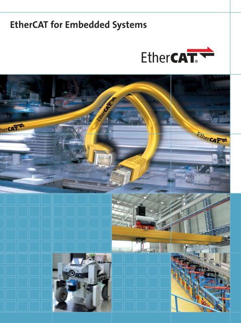
<strong>EtherCAT</strong> <strong>for</strong> <strong>Embedded</strong> <strong>Systems</strong>
■ Content<br />
2 <strong>EtherCAT</strong> Technology Group 3<br />
<strong>EtherCAT</strong> Technology Group<br />
3 Why <strong>EtherCAT</strong> <strong>for</strong> <strong>Embedded</strong> <strong>Systems</strong>?<br />
4 User and Vendor Statements<br />
6 <strong>EtherCAT</strong> Technology Group<br />
8 <strong>EtherCAT</strong> – Technical Introduction and Overview<br />
16 Implementation Aspects<br />
19 Application Examples<br />
20 Contact<br />
© <strong>EtherCAT</strong> Technology Group. We reserve the right to make technical changes. © <strong>EtherCAT</strong> Technology Group. All rights reserved.<br />
■ It’s faster<br />
| The fastest system available,<br />
with outstanding synchronization features<br />
| Per<strong>for</strong>mance widely independent of topology<br />
| No underlying sub-system required any more<br />
| Meets today’s and tomorrow’s requirements<br />
■ It’s cost effective<br />
| Meets or even undercuts fieldbus cost levels<br />
| No special master cards required –<br />
on-board MAC or low cost standard NIC is fine<br />
| Highly integrated Slave Controllers <strong>for</strong><br />
lower interface costs<br />
| No active infrastructure components required<br />
■ It’s easy to implement<br />
| Real-time protocol handling in hardware<br />
| Device application determines μC per<strong>for</strong>mance –<br />
not the fieldbus protocol<br />
| Simple I/O slaves do not require μC at all<br />
| Universal slave interface modules available<br />
| Evaluation kits and stacks <strong>for</strong> master<br />
and slave available<br />
■ It’s easy to use<br />
| No manual address setting<br />
| No switch configuration<br />
| Auto configuration features<br />
| Diagnosis with exact localization<br />
■ It’s flexible topology<br />
| All topologies supported: line, tree, star, ring<br />
| No node, switch or hub cascading issues<br />
| Up to 65,535 nodes per segment<br />
| Redundancy, Hot Connect, Hot Swap options<br />
■ It’s versatile<br />
| master-slave, slave-slave and<br />
master-master communication<br />
| Cyclic and acyclic services <strong>for</strong> process data<br />
and parameter data<br />
| Suitable <strong>for</strong> centralized and distributed control<br />
architectures<br />
| Machine control, robotics, embedded systems,<br />
building automation, transport systems, …<br />
■ It’s Industrial Ethernet<br />
| Standard Ethernet frames used<br />
| Supports all Internet technologies<br />
| HTTP, FTP, TCP/IP – without degrading<br />
the real-time behavior<br />
| Simplifies vertical integration<br />
■ It’s Safety on Ethernet<br />
| Functional Safety and standard application<br />
with one network<br />
| Safety Protocol according to international<br />
safety standard IEC 61508<br />
| Suitable <strong>for</strong> safety I/O and safety drives<br />
| Routable via gateways and fieldbus systems<br />
■ It’s open<br />
| Open Technology, fully disclosed<br />
| Supported by the worlds largest Industrial<br />
Ethernet Organization<br />
| <strong>EtherCAT</strong> is IEC and ISO standard<br />
| Supports well established device profiles<br />
■ It’s well proven<br />
| Deployed in series applications since 2003<br />
| Wide range of applications<br />
| Implemented on variety of controllers and<br />
operating systems<br />
| Large product selection
■ User and Vendor Statements<br />
4 <strong>EtherCAT</strong> Technology Group 5<br />
<strong>EtherCAT</strong> Technology Group<br />
■ Martin Rostan, Head of Technology<br />
Marketing, Beckhoff Automation GmbH,<br />
and Executive Director,<br />
<strong>EtherCAT</strong> Technology Group:<br />
“The strong growth of the <strong>EtherCAT</strong> Technology Group<br />
reflects the tremendous worldwide interest in this<br />
exiting technology. Manufacturers and end users recognize<br />
the benefits: future-proof per<strong>for</strong>mance, flexible network topology, simple<br />
configuration, and low costs. Nevertheless, while the number of members is an<br />
important criterion <strong>for</strong> the success of a technology organization, it is not the crucial<br />
one. Acceptance of the technology resulting in product developments and applications<br />
is even more important. Here too, <strong>EtherCAT</strong> is setting standards.”<br />
■ Erich Hutflesz, Manager Control <strong>Systems</strong>,<br />
Schuler SMG, and ETG Board Member:<br />
“<strong>EtherCAT</strong> enables us to realize fast drive and hydraulic<br />
controls <strong>for</strong> all applications currently used in the<br />
Schuler Group. Another crucial factor is that, due to<br />
<strong>EtherCAT</strong>’s per<strong>for</strong>mance, we still have enough potential<br />
<strong>for</strong> solving complex control tasks in future without<br />
speed problems. Apart from the functional features of a technology, availability<br />
of a wide range of components is very significant <strong>for</strong> users of automation devices.<br />
The fact that so shortly after ETG was established so many member companies<br />
were already presenting <strong>EtherCAT</strong> products and that further products are in<br />
preparation is clear evidence <strong>for</strong> the success of this technology. The main factor<br />
determining user acceptance continues to be simple and effective handling of<br />
the <strong>EtherCAT</strong> system in terms of configuration and diagnosis.”<br />
■ Dr. Peter Heidrich, R&D Manager,<br />
Baumüller GmbH, and ETG Board Member:<br />
“Baumüller decided to use <strong>EtherCAT</strong> due to the significant<br />
benefits it can offer, particularly in terms of price/per<strong>for</strong>mance<br />
ratio and availability. This decision<br />
was underlined through our active collaboration in<br />
the ETG executive committee. We continue to be convinced<br />
that the decision <strong>for</strong> <strong>EtherCAT</strong> was the right one. As soon as <strong>EtherCAT</strong> Slave<br />
Controllers became available, Baumüller started producing connections <strong>for</strong> the<br />
bmaXX 4400 system in August 2004. ETG has demonstrated that, due to the universality<br />
of the <strong>EtherCAT</strong> technology, <strong>EtherCAT</strong>-based systems can be developed<br />
and realized very quickly.”<br />
■ Dieter Hess, Managing<br />
Director, 3S Smart Software<br />
Solutions GmbH:<br />
“3S decided to implement <strong>EtherCAT</strong> as<br />
the first real-time Ethernet protocol,<br />
since <strong>EtherCAT</strong> utilizes the maximum<br />
per<strong>for</strong>mance of Ethernet. For us as a<br />
software manufacturer, the fact that the master implementation<br />
is independent of special plug-in cards is particularly attractive.<br />
The software can be based on the universally available standard<br />
Ethernet controller. The openness of the system and active support<br />
of Beckhoff <strong>for</strong> ETG are further significant factors.”<br />
■ Kenichi Karigane,<br />
General Manager,<br />
Drive <strong>Systems</strong> Division,<br />
Product Marketing & Sales<br />
Engineering Center,<br />
Hitachi IES Co., Ltd.:<br />
“We have investigated major Industrial<br />
Ethernet Solutions and are very interested in the <strong>EtherCAT</strong> technology.<br />
The <strong>EtherCAT</strong> per<strong>for</strong>mance together with its synchronization<br />
capabilities make it particular suitable <strong>for</strong> demanding motion<br />
control applications. The ease of use and the real-time features<br />
will make <strong>EtherCAT</strong> the network of choice also <strong>for</strong> other application<br />
areas, and Hitachi-IES has joined the ETG.<br />
We expect the <strong>EtherCAT</strong> technology to become an approach to<br />
success <strong>for</strong> our motion control business.“<br />
■ Kim Hartman, VP Sales &<br />
Marketing, TenAsys Corporation:<br />
“The <strong>EtherCAT</strong> standard has potential<br />
to be a significant and disruptive technology<br />
in lowering costs and improving<br />
per<strong>for</strong>mance of hard real-time Ethernet<br />
based fieldbus applications. As a 25-year<br />
supplier of the RTOS iRMX and INtime <strong>for</strong> Windows TenAsys is particularly<br />
aware of the highly optimized structure used in <strong>EtherCAT</strong><br />
telegrams. We’re very pleased to be associated with the ETG, and in<br />
putting <strong>for</strong>th ef<strong>for</strong>t towards supplying a robust, and high per<strong>for</strong>mance<br />
real-time <strong>EtherCAT</strong> master <strong>for</strong> OEM application.”<br />
■ Thomas Porath,<br />
System Architect General X-Ray,<br />
Philips Medical <strong>Systems</strong>:<br />
“We believe that <strong>EtherCAT</strong> is the right<br />
technology <strong>for</strong> the next step towards a system<br />
control architecture that enables us to<br />
further reduce costs and allows <strong>for</strong> new innovations,<br />
which the current architecture is not suitable to serve <strong>for</strong>. The<br />
per<strong>for</strong>mance of <strong>EtherCAT</strong> will allow us to implement hard real-time, safety,<br />
and control-functions on one single cable, while simultaneously offering<br />
flexible topologies, which will reduce cable-costs significantly.<br />
Not only per<strong>for</strong>mance, but also international standardization and worldwide<br />
acceptance are important features of <strong>EtherCAT</strong>. Our changeover to<br />
<strong>EtherCAT</strong> is simplified through the use of CANopen device profiles and the<br />
availability of gateways and converters, since we are not able to convert<br />
all of our subsystems and components in one big step.”<br />
■ Pat Boland, Managing Director,<br />
ANCA Pty Ltd.:<br />
“ANCA’s interest in <strong>EtherCAT</strong> as the standard<br />
fieldbus in our CNC machines has<br />
been driven by three main features. Firstly<br />
there is the practically unlimited bandwidth<br />
offered by <strong>EtherCAT</strong> which gives our<br />
designers freedom to imagine, scalability and long product lifetime. Secondly<br />
the two physical layers give the option of choosing low cost, electrically<br />
rugged and widely available hardware components. Finally the<br />
software only master allows easy use of high reliability, relatively low cost<br />
industrial motherboards as system controllers.”<br />
© <strong>EtherCAT</strong> Technology Group. All rights reserved. © <strong>EtherCAT</strong> Technology Group. All rights reserved.<br />
■ Hans Beckhoff,<br />
Managing Director,<br />
Beckhoff GmbH:<br />
“Naturally, <strong>EtherCAT</strong> is particularly suitable<br />
<strong>for</strong> fast PC-based controls. The master requires<br />
no plug-in card and can be implemented<br />
on any existing Ethernet controller<br />
using a very simple interface. <strong>EtherCAT</strong> is there<strong>for</strong>e also well suited to<br />
small and medium control technology, where it opens up new areas of<br />
application <strong>for</strong> distributed control. There<strong>for</strong>e <strong>EtherCAT</strong> is the communication<br />
backbone of Beckhoff system architecture and we are very pleased<br />
about the worldwide success of this technology.”<br />
■ Norbert Hauser,<br />
VP Marketing,<br />
Kontron AG:<br />
“<strong>EtherCAT</strong> is currently the most successful<br />
Ethernet-based fieldbus. This is also visible in<br />
the strongly growing number of members of<br />
renowned companies. A major advantage of<br />
<strong>EtherCAT</strong> is its openness, high per<strong>for</strong>mance and the excellent price-per<strong>for</strong>mance<br />
ratio. Kontron‘s embedded computing customers have identified<br />
the advantages of <strong>EtherCAT</strong> <strong>for</strong> their business. There<strong>for</strong>e, Kontron,<br />
one of the leading companies in the <strong>Embedded</strong> Computing market, has<br />
decided to offer the embedded portfolio also with <strong>EtherCAT</strong>.”<br />
■ Chris Choi,<br />
Director of Technology, Husky<br />
Injection Molding <strong>Systems</strong> Ltd.:<br />
“Keeping our customers in the lead is never<br />
easy! One of the means to sustain this capability<br />
is a continuous renewal of our controls<br />
technology. In our pursuit of the next generation<br />
of controls, <strong>EtherCAT</strong> stands out as a fieldbus technology with the<br />
best value. No PCI interface card means lower fieldbus cost, lower PC cost<br />
and ultimately lower system cost.The unique address mapping technique<br />
of <strong>EtherCAT</strong> brings the real-time industrial Ethernet to reach its highest<br />
potential. We are yet to be convinced otherwise by other contenders that<br />
they are both technically and economically superior to <strong>EtherCAT</strong>.”<br />
■ Dmitry Dzilno, Manager,<br />
Controls Group,<br />
Applied Materials Inc.:<br />
“We have evaluated <strong>EtherCAT</strong> and find especially<br />
exciting that this communication technology<br />
allows to connect fieldbus scanner cards,<br />
digital motion amplifiers as well as fast I/O using<br />
just one Ethernet port instead of multiple PCI slots. Introducing Ether-<br />
CAT hence does not require abandoning all well established fieldbus systems<br />
right away but provides a smooth migration path especially in demanding<br />
motion control applications.”
■ <strong>EtherCAT</strong> Technology Group<br />
6 <strong>EtherCAT</strong> Technology Group<br />
Everyone should be able to use and implement <strong>EtherCAT</strong>.<br />
The <strong>EtherCAT</strong> Technology Group stands <strong>for</strong> this philosophy.<br />
The ETG is a <strong>for</strong>um <strong>for</strong> end users from different sectors, and<br />
<strong>for</strong> machine manufacturers and suppliers of powerful control<br />
technology with the aim of supporting and promoting<br />
<strong>EtherCAT</strong> technology. The wide range of industry sectors<br />
that are represented ensures that <strong>EtherCAT</strong> is optimally<br />
prepared <strong>for</strong> a large number of applications. With their<br />
qualified feedback, the system partners ensure simple integration<br />
of the hardware and software components in all<br />
required device classes.<br />
The ETG Technical Committee meets frequently to review<br />
the technology. Technical Task Forces look after topics<br />
like device profile integration, safety, wiring, standardization<br />
or test and certification.<br />
In Training Classes and Seminars the ETG provides detailed<br />
in<strong>for</strong>mation about the Technology.<br />
The Management Board of the International Electrotechnical<br />
Commission (IEC) approved the Liaison of the<br />
<strong>EtherCAT</strong> Technology Group with the IEC Committee <strong>for</strong><br />
Digital Communication: The ETG is official standardization<br />
partner organization.<br />
Benefits of membership<br />
■ Member companies receive access to specification<br />
drafts, specifications, white papers, tools, prototype evaluation<br />
products and initial batch products and thus have<br />
a head start in evaluating, using or implementing the<br />
<strong>EtherCAT</strong> technology.<br />
■ Members are eligible to participate in working groups<br />
and gain influence on future enhancements of the Ether-<br />
CAT technology specifications.<br />
■ ETG represent the member’s interest in international<br />
standardization committees such as IEC and ISO.<br />
■ ETG members have access to the members-only part of<br />
the <strong>EtherCAT</strong> website, which provides specifications still in<br />
development, a developers <strong>for</strong>um and up-to date in<strong>for</strong>mation<br />
regarding the technology.<br />
© <strong>EtherCAT</strong> Technology Group. All rights reserved.<br />
© <strong>EtherCAT</strong> Technology Group. All rights reserved.<br />
■ The ETG offices answers technical inquiries regarding<br />
<strong>EtherCAT</strong>, provide marketing assistance, publish product<br />
guides, issue press releases and articles, promote <strong>EtherCAT</strong><br />
via its website and organize joint fair and exhibition<br />
booths.<br />
International Standardization<br />
The <strong>EtherCAT</strong> specification is an international IEC and ISO<br />
standard: <strong>EtherCAT</strong> is part of the international fieldbus<br />
standard, IEC 61158 (Digital data communication <strong>for</strong> measurement<br />
and control – Fieldbus <strong>for</strong> use in industrial control<br />
systems). As part of the IEC 61784-2 (Industrial communication<br />
networks – Part 2: Additional profiles <strong>for</strong> ISO/<br />
IEC 8802-3 based communication networks in real-time<br />
applications) profiles <strong>for</strong> specific <strong>EtherCAT</strong> device classes<br />
are defined.<br />
The IEC 61800-7 is particularly important <strong>for</strong> Motion<br />
Control applications. The integration of <strong>EtherCAT</strong> in this<br />
standard makes it a standardized communication technology<br />
<strong>for</strong> the SERCOS* and CANopen drive profiles.<br />
<strong>EtherCAT</strong> Technology Group 7<br />
Also the SEMI (Semiconductor Equipment and Materials<br />
International) has approved <strong>EtherCAT</strong> <strong>for</strong> their applications<br />
by accepting the <strong>EtherCAT</strong> SEMI standard. The leading<br />
standards organizations thus respond to the growing<br />
interest of the industry in the fastest Industrial Ethernet<br />
solution.<br />
Membership Development<br />
Founded in 2003, the <strong>EtherCAT</strong> Technology Group grew so<br />
fast that it can be considered the world’s largest Industrial<br />
Ethernet organization. With members from all over the<br />
world and still growing, the ETG is a strong international<br />
community. The current membership list can be found on<br />
the <strong>EtherCAT</strong> website.<br />
“SERCOS Interface” is a trade name of SI e.V.
■ Technical Introduction and Overview<br />
8 <strong>EtherCAT</strong> Technology Group 9<br />
<strong>EtherCAT</strong> Technology Group<br />
This section provides an in-depth introduction into <strong>EtherCAT</strong>, the Ethernet-based fieldbus system.<br />
<strong>EtherCAT</strong> sets new per<strong>for</strong>mance standards. Handling is straight<strong>for</strong>ward and similar to a fieldbus, thanks<br />
to flexible topology and simple configuration. Moreover, since <strong>EtherCAT</strong> can be implemented very<br />
cost-effectively, the system enables fieldbuses to be used in applications where fieldbus networking<br />
was not an option in the past.<br />
■ Introduction<br />
Fieldbuses have become an integrated component of automation<br />
technology. They have been tried and tested and<br />
are now widely established. It was fieldbus technology<br />
that enabled the wide-scale application of PC-based control<br />
systems. While the per<strong>for</strong>mance of controller CPUs –<br />
particularly <strong>for</strong> IPCs – is increasing rapidly, conventional<br />
fieldbus systems tend to represent “bottlenecks” that limit<br />
the per<strong>for</strong>mance control systems can achieve. An additional<br />
factor is the layered control architecture consisting<br />
of several subordinate (usually cyclic) systems: the actual<br />
control task, the fieldbus system and perhaps local expansion<br />
buses within the I/O system or simply the local<br />
firmware cycle in the peripheral device. Reaction times are<br />
typically 3–5 times higher than the controller cycle time –<br />
an unsatisfactory solution.<br />
Above the fieldbus system level, i.e. <strong>for</strong> networking<br />
controllers, Ethernet has already been the state of the art<br />
<strong>for</strong> some time. What is relatively new is its application at<br />
the drive or I/O level, i.e. in areas that were dominated by<br />
Input<br />
Conversion<br />
Input<br />
Communication<br />
I/O Response Time 100 µs<br />
Logic Calculation Output Output<br />
Commu- Conversion<br />
nication<br />
fieldbus systems in the past. The main requirements <strong>for</strong><br />
this type of application are high real-time capability, suitability<br />
<strong>for</strong> small data quantities, and naturally cost-effectiveness.<br />
<strong>EtherCAT</strong> meets these requirements and at the<br />
same time makes internet technologies available at the<br />
I/O level.<br />
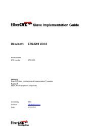
With <strong>EtherCAT</strong> the controller can update the input<br />
and/or output in<strong>for</strong>mation at the time when the data is<br />
needed. The I/O response time contains all hardware relevant<br />
delays (IPC, <strong>EtherCAT</strong> and I/O system) from the physical<br />
input signal to the physical reaction on the output.<br />
With a time of ≤ 100 μs this offers a per<strong>for</strong>mance to<br />
the PLC level that has been available up to now only<br />
within servo drives with a digital signal processor (DSP),<br />
(see Fig. 1).<br />
■ Ethernet and real-time capability<br />
There are many different approaches that try and provide<br />
real-time capability <strong>for</strong> Ethernet: <strong>for</strong> example, the CS-<br />
MA/CD media access procedure is disabled via higher level<br />
■ Figure 1: Ultra short cylce times with I/O response time < 100 μs ■ Figure 2: Process data is inserted in datagram<br />
© <strong>EtherCAT</strong> Technology Group. All rights reserved. © <strong>EtherCAT</strong> Technology Group. All rights reserved.<br />
protocol layers and replaced by the time slice procedure or<br />
polling; other propositions use special switches that distribute<br />
Ethernet packets in a precisely controlled timely<br />
manner. Whilst these solutions may be able to transport<br />
data packets more or less quickly and accurately to the<br />
connected Ethernet nodes, the times required <strong>for</strong> the redirection<br />
to the outputs or drive controllers and <strong>for</strong> reading<br />
the input data strongly depend on the implementation.<br />
If individual Ethernet frames are used <strong>for</strong> each device,<br />
the usable data rate is very low in principle: The shortest<br />
Ethernet frame is 84 bytes long (incl. inter-packet gap IPG).<br />
If, <strong>for</strong> example, a drive cyclically sends 4 bytes of actual value<br />
and status in<strong>for</strong>mation and accordingly receives 4 bytes<br />
of command value and control word in<strong>for</strong>mation, at 100 %<br />
bus load (i.e. with infinitely short response time of the<br />
drive) a usable data rate of only 4/84 = 4.8 % is achieved. At<br />
an average response time of 10 μs, the rate drops to 1.9 %.<br />
These limitations apply to all real-time Ethernet approaches<br />
that send an Ethernet frame to each device (or expect a<br />
frame from each device), irrespective of the protocols used<br />
within the Ethernet frame.<br />
■ <strong>EtherCAT</strong> operating principle<br />
<strong>EtherCAT</strong> technology overcomes these inherent limitations<br />
of other Ethernet solutions: On the one hand the Ethernet<br />
packet is no longer received then interpreted and process<br />
data then copied at every device, but the <strong>EtherCAT</strong> slave<br />
devices read the data addressed to them while the frame<br />
Ethernet Header ECAT HDR Datagram 1 Datagram 2 Datagram 3 Ethernet<br />
Logical Process Image<br />
Task 1<br />
Logical Process Image<br />
Task 2<br />
Logical Process Image<br />
Task 3<br />
passes through the node. Similarly, input data is inserted<br />
while the telegram passes through (see Fig. 2). The frames<br />
are only delayed by a few nanoseconds. The frame send by<br />
the master is passed through to the next device until it<br />
reaches the end of the segment (or branch). The last device<br />
detects an open port and there<strong>for</strong>e sends the frame back<br />
to the master.<br />
On the other hand, an <strong>EtherCAT</strong> frame comprises the<br />
data of many devices both in send and receive direction<br />
within one Ethernet frame. The usable data rate increases<br />
to over 90 %. The full-duplex features of 100BaseTX are fully<br />
utilized, so that effective data rates of > 100 Mb/s (> 90 %<br />
of 2 x 100 Mb/s) can be achieved (see Fig. 3).<br />
The <strong>EtherCAT</strong> master uses standard Ethernet Medium<br />
Access Controllers (MACs) without extra communication<br />
processors. Thus an <strong>EtherCAT</strong> master can be implemented<br />
on any equipment controller that provides an Ethernet interface,<br />
independently of the operating system or application<br />
environment.<br />
The <strong>EtherCAT</strong> slave uses an <strong>EtherCAT</strong> Slave Controller<br />
(ESC) <strong>for</strong> processing the data on-the-fly. Thus the per<strong>for</strong>mance<br />
of the network is not determined by the microcontroller<br />
per<strong>for</strong>mance of the slave but is handled complete in<br />
hardware. A process data interface (PDI) to the slave‘s application<br />
offers a Dual-Port-RAM <strong>for</strong> data exchange.<br />
■ Figure 3: Comparison of Bandwidth Utilisation<br />
100<br />
90<br />
80<br />
70<br />
60<br />
50<br />
40<br />
30<br />
20<br />
10<br />
0<br />
2-5%<br />
Polling/<br />
Timeslicing<br />
20-30%<br />
Broadcast<br />
Master➝Slave<br />
At 4 Byte user data<br />
per note<br />
80-97%<br />
<strong>EtherCAT</strong><br />
From 2 Bit<br />
user data<br />
per note
10 <strong>EtherCAT</strong> Technology Group<br />
■ Protocol<br />
<strong>EtherCAT</strong> only uses standard frames according to IEEE<br />
802.3 – the frames are not shortened. <strong>EtherCAT</strong> frames can<br />
thus be sent from any Ethernet controller (master), and<br />
standard tools (e.g. monitor) can be used.<br />
The <strong>EtherCAT</strong> protocol is optimized <strong>for</strong> process data<br />
and is transported directly within the Ethernet frame<br />
thanks to a special Ether type. It may consist of several<br />
<strong>EtherCAT</strong> datagrams, each serving a particular memory<br />
area within the 4 gigabyte address space. This memory is<br />
available in the segment <strong>for</strong> process data and is used as a<br />
distributed memory. For small I/O devices the <strong>EtherCAT</strong><br />
Slave Controller also supports bitwise mapping. The bits of<br />
an input device can be inserted individually anywhere<br />
within the logical address space. If an <strong>EtherCAT</strong> datagram<br />
is sent that reads or writes a certain process image area<br />
the input terminal inserts its data at the right place within<br />
the data area. This is done by the Fieldbus Memory Management<br />
Unit (FMMU) within the ESC. So the data sequence<br />
becomes independent of the physical order of the<br />
Ethernet terminals in the network; addressing can be in<br />
any order. Broadcast, Multicast and communication between<br />
slaves are possible. Direct Ethernet frame transfer is<br />
used in cases where maximum per<strong>for</strong>mance is required<br />
and the <strong>EtherCAT</strong> components are operated in the same<br />
subnet as the controller.<br />
However, <strong>EtherCAT</strong> applications are not limited to a<br />
single subnet: <strong>EtherCAT</strong> UDP packages the <strong>EtherCAT</strong> proto-<br />
■ Figure 4: <strong>EtherCAT</strong>: Standard Frames according to IEEE 802.3 [3]<br />
Ethernet Header<br />
ECAT<br />
<strong>EtherCAT</strong> Telegram<br />
Ethernet<br />
DA SA Type Frame HDR Datagram 1 Datagram 2 -- Datagram n Pad. FCS<br />
(6)<br />
Ethertype 88A4h<br />
(6) (2/4) (2) (10+n+2) (10+m+2) (10+k+2) (0…32) (4)<br />
Ethernet<br />
Header<br />
IP Header UDP Header ECAT HDR <strong>EtherCAT</strong> Telegram<br />
Ethertype 0800h<br />
UDP-Port: 88A4h<br />
(20) (8)<br />
col into UDP/IP datagrams (see Fig. 4). This enables any<br />
control with Ethernet protocol stack to address <strong>EtherCAT</strong><br />
systems. Even communication across routers into other<br />
subnets is possible. In this variant, system per<strong>for</strong>mance obviously<br />
depends on the real-time characteristics of the control<br />
and its Ethernet protocol implementation. The response<br />
times of the <strong>EtherCAT</strong> network itself are hardly restricted<br />
at all: the UDP datagram only has to be unpacked<br />
in the first station.<br />
To access the local memory of the devices <strong>for</strong> example<br />
<strong>for</strong> configuration either the position of the devices in the<br />
segment can be addressed or the device is addressed via an<br />
assigned fixed address.This means: No manual address adjustment<br />
on the devices is needed!<br />
The position addressing is used <strong>for</strong> the boot-up of the<br />
network. The master can identify each device in the segment<br />
(Vendor-ID, product code, etc.) and can read in the<br />
link status of the device‘s ports. There<strong>for</strong>e the complete in<strong>for</strong>mation<br />
about all devices and about the topology is<br />
available and can be compared to an expected configuration.<br />
Additionally, the master assigns a fixed address to all<br />
devices.<br />
This fixed address is used afterwards and addresses the<br />
devices reliably even if one or more devices are not connected<br />
(e.g. Hot-plug groups) and there<strong>for</strong>e the position in<br />
the segment is not the same.<br />
In addition to data exchange according to the master/slave<br />
principle, <strong>EtherCAT</strong> is also very suitable <strong>for</strong> com-<br />
Ethernet<br />
© <strong>EtherCAT</strong> Technology Group. All rights reserved.<br />
© <strong>EtherCAT</strong> Technology Group. All rights reserved.<br />
munication between controllers (master/master). Freely<br />
addressable network variables <strong>for</strong> process data and a variety<br />
of services <strong>for</strong> parameterization, diagnosis, programming<br />
and remote control cover a wide range of requirements.<br />
The data interfaces <strong>for</strong> master/slave and master/master<br />
communication are identical.<br />
For slave-to-slave communication, two mechanisms<br />
are available. Upstream devices can communicate to<br />
downstream devices within the same cycle – and thus extremely<br />
fast. Since this method is topology-dependent, it is<br />
particularly suitable <strong>for</strong> slave-to-slave communication relationships<br />
given by machine design – e.g. in printing or<br />
packaging applications. For freely configurable slave-toslave<br />
communication, the second mechanism applies: the<br />
data is relayed by the master. Here, two cycles are needed,<br />
but due to the extraordinary per<strong>for</strong>mance of <strong>EtherCAT</strong> this<br />
is still faster than any other approach.<br />
<strong>EtherCAT</strong> only uses standard frames according to [3] –<br />
the frames are not shortened. <strong>EtherCAT</strong> frames can thus be<br />
sent from any Ethernet MAC, and standard tools (e.g. monitor)<br />
can be used.<br />
■ Topology<br />
Line, tree or star: <strong>EtherCAT</strong> supports almost any topology<br />
(see Fig. 5). The bus or line structure known from the fieldbuses<br />
thus also becomes available <strong>for</strong> Ethernet, without<br />
the quantity limitations implied by cascaded switches or<br />
hubs.<br />
■ Figure 5: Flexible Topology: Line, Tree or Star<br />
<strong>EtherCAT</strong> Technology Group<br />
Particularly useful <strong>for</strong> system wiring is the combination<br />
of line and branches or stubs: the required interfaces<br />
exist on many devices (e.g. on I/O modules); no additional<br />
switches are required. Naturally, the classic switch-based<br />
Ethernet star topology can also be used.<br />
Wiring flexibility is further maximized through the<br />
choice of different cables. Flexible and inexpensive standard<br />
Ethernet cables transfer the signals in 100BASE-TX<br />
mode. Plastic optical fibers (POF) will complement the system<br />
<strong>for</strong> special applications. The complete choice of Ethernet<br />
wiring – such as different optical fibers and copper cables<br />
– can be used in combination with switches or media<br />
converters.<br />
The Fast Ethernet physics (100BASE-TX) enables a cable<br />
length of 100 m between two devices. Since up to 65,535<br />
devices can be connected, the size of the network is almost<br />
unlimited.<br />
The Ethernet protocol according to IEEE 802.3 remains<br />
intact right up to the individual device; no sub-bus is required.<br />
In order to meet the requirements of a modular device<br />
like an electronic terminal block, the physical layer in<br />
the coupling device can be converted from twisted pair or<br />
optical fiber to LVDS (alternative Ethernet physical layer,<br />
standardized in [4,5]). A modular device can thus be extended<br />
very cost-efficiently. Subsequent conversion from<br />
the backplane physical layer LVDS to the 100BASE-TX physical<br />
layer is possible at any time – as usual with Ethernet.<br />
11
12 <strong>EtherCAT</strong> Technology Group<br />
■ Distributed clocks<br />
Accurate synchronization is particularly important in cases<br />
where spatially distributed processes require simultaneous<br />
actions. This may be the case, <strong>for</strong> example, in applications<br />
where several servo axes carry out coordinated movements<br />
simultaneously.<br />
The most powerful approach <strong>for</strong> synchronization is the<br />
accurate alignment of distributed clocks, as described <strong>for</strong><br />
example in the IEEE 1588 standard [6]. In contrast to fully<br />
synchronous communication, where synchronization quality<br />
suffers immediately in the event of a communication<br />
fault, distributed aligned clocks have a high degree of tolerance<br />
versus possible fault-related delays within the communication<br />
system.<br />
With <strong>EtherCAT</strong>, the synchronization of the devices is<br />
fully based on a pure hardware machine. Since the communication<br />
utilizes a logical (and thanks to full-duplex Fast<br />
Ethernet also physical) ring structure, a timestamp can be<br />
sampled within each device <strong>for</strong> the incoming and the returning<br />
frame. With these timestamps the master can determine<br />
the propagation delay offset to the individual<br />
slave clocks simply and accurately (see Fig. 7). The distributed<br />
clocks are adjusted based on this value, which means<br />
that a very precise network-wide time base with a jitter of<br />
significantly less then 1 microsecond is available (see<br />
Fig. 6). External synchronization, e.g. across the plant, is<br />
then based on IEEE 1588. However, high-resolution distributed<br />
clocks are not only used <strong>for</strong> synchronization, but can<br />
■ Figure 6: Synchronicity and Simultaneousness: Scope view of two distributed<br />
devices with 300 nodes and 120m of cable between them<br />
also provide accurate in<strong>for</strong>mation about the local timing<br />
of the data acquisition. For example, motion controllers<br />
typically calculate velocities from sequentially measured<br />
positions. Particularly with very short sampling times, even<br />
a small temporal jitter in the position measurement leads<br />
to large step changes in the computed velocity.With Ether-<br />
CAT, timestamp data types are introduced as a logical extension.<br />
The high resolution system time is linked to the<br />
measured value, which is made possible by the large bandwidth<br />
offered by Ethernet. The accuracy of a velocity calculation<br />
then no longer depends on the jitter of the communication<br />
system. It is orders of magnitude better than that<br />
of measuring techniques based on jitter-free communication.<br />
■ Per<strong>for</strong>mance<br />
<strong>EtherCAT</strong> reaches new dimensions in network per<strong>for</strong>mance.<br />
Thanks to hardware integration in the slave and direct<br />
memory access to the network controller in the master,<br />
the complete protocol processing takes place within<br />
hardware and is thus fully independent of the run-time of<br />
protocol stacks, CPU per<strong>for</strong>mance or software implementation.<br />
The update time <strong>for</strong> 1,000 I/Os is only 30 μs – including<br />
I/O cycle time (see Table 1). Up to 1486 bytes of<br />
process data can be exchanged with a single Ethernet<br />
frame – this is equivalent to almost 12,000 digital inputs<br />
and outputs. The transfer of this data quantity only takes<br />
150 μs. The communication with 100 servo axes is also ex-<br />
■ Figure 7: Setting the indivual clocks of each device to the network-wide time base.<br />
M<br />
Δt<br />
s<br />
s s s s s<br />
s<br />
© <strong>EtherCAT</strong> Technology Group. All rights reserved.<br />
■ Table 1: <strong>EtherCAT</strong> Per<strong>for</strong>mance Overview<br />
© <strong>EtherCAT</strong> Technology Group. All rights reserved.<br />
tremely fast: every 100 μs, all axes are provided with command<br />
values and control data and report their actual position<br />
and status. The distributed clock technique enables<br />
the axes to be synchronized with a deviation of significantly<br />
less than 1 microsecond. And even at this pace, there<br />
is more than sufficient bandwidth <strong>for</strong> asynchronous communications<br />
such as TCP/IP, parameter download or diagnostic<br />
data upload.<br />
The extremely high per<strong>for</strong>mance of the <strong>EtherCAT</strong> technology<br />
enables control concepts that could not be realized<br />
with classic fieldbus systems. With <strong>EtherCAT</strong>, a communication<br />
technology is available that matches the superior<br />
computing capacity of modern Industrial PCs. The bus system<br />
is no longer the bottleneck of the control concept. Distributed<br />
I/Os are recorded faster than is possible with most<br />
local I/O interfaces. The <strong>EtherCAT</strong> technology principle is<br />
scalable and not bound to the baud rate of 100 Mbaud –<br />
extension to Gbit Ethernet is possible.<br />
■ Diagnosis<br />
Experience with fieldbus systems shows that availability<br />
and commissioning times crucially depend on the diagnostic<br />
capability. Only faults that are detected quickly and<br />
accurately and located unambiguously can be rectified<br />
quickly. There<strong>for</strong>e, special attention was paid to exemplary<br />
diagnostic features during the development of <strong>EtherCAT</strong>.<br />
During commissioning, the actual configuration of the<br />
nodes (e.g. drives or I/O terminals) should be checked <strong>for</strong><br />
Process Data Update Time<br />
256 distributed digital I/O 11 μs = 0,01 ms<br />
1000 distributed digital I/O 30 μs<br />
200 analog I/O (16 bit) 50μs ↔ 20 kHz<br />
100 Servo Axis, with 8 Bytes<br />
input and output data each<br />
100 μs<br />
1 Fieldbus Master-Gateway<br />
(1486 Bytes Input and<br />
1486 Bytes Output Data)<br />
150 μs<br />
■ Figure 8: Low cost cable redundancy with standard slaves<br />
<strong>EtherCAT</strong> Technology Group<br />
consistency with the specified configuration. The topology<br />
should also match the configuration. Due to the built-in<br />
topology recognition down to the individual terminals,<br />
this verification can not only take place during system<br />
start-up, automatic reading in of the network is also possible<br />
(configuration up-load).<br />
Bit faults during the transfer are reliably detected<br />
through evaluation of the CRC checksum: The 32 bit CRC<br />
polynomial has a minimum hamming distance of 4. Apart<br />
from broken wire detection and localization, the protocol,<br />
physical layer and topology of the <strong>EtherCAT</strong> system enable<br />
individual quality monitoring of each individual transmission<br />
segment. The automatic evaluation of the associated<br />
error counters enables precise localization of critical network<br />
sections. Gradual or changing sources of error such as<br />
EMI influences, defective connectors or cable damage are<br />
detected and located, even if they do not yet overstrain the<br />
self healing capacity of the network.<br />
■ High availability<br />
Increasing demands in terms of system availability are<br />
catered <strong>for</strong> with optional cable redundancy that enables<br />
devices to be exchanged without having to shut down the<br />
network. Adding redundancy is very inexpensive: the only<br />
additional hardware is another standard Ethernet port (no<br />
special card or interface) in the master device and the single<br />
cable that turns the line topology into the ring (see<br />
Fig. 8). Switchover in case of device or cable failure only<br />
13
14 <strong>EtherCAT</strong> Technology Group<br />
takes one cycle, so even demanding motion control applications<br />
survive a cable failure without problems. <strong>EtherCAT</strong><br />
also supports redundant masters with hot standby functionality.<br />
Since the <strong>EtherCAT</strong> Slave Controllers immediately<br />
return the frame automatically if an interruption is encountered,<br />
failure of a device does not necessarily lead to<br />
the complete network being shut down. Drag chain applications,<br />
<strong>for</strong> example, can thus be specifically configured as<br />
stubs in order to be prepared <strong>for</strong> cable break.<br />
■ Safety<br />
Conventionally, safety functions are realized separately<br />
from the automation network, either via hardware or using<br />
dedicated safety bus systems. Safety over <strong>EtherCAT</strong> enables<br />
safety-related communication and control communication<br />
on the same network. The safety protocol is based<br />
on the application layer of <strong>EtherCAT</strong>, without influencing<br />
the lower layers. It is certified according to IEC 61508 and<br />
meets the requirements of Safety Integrity Level (SIL) 3.The<br />
data length is variable, making the protocol equally suitable<br />
<strong>for</strong> safe I/O data and <strong>for</strong> safe drive technology. There<br />
are no restrictions regarding the communication medium<br />
or the transfer rate. Like other <strong>EtherCAT</strong> data, the safety data<br />
can be routed without requiring safety routers or gateways.<br />
First fully certified products featuring Safety over<br />
<strong>EtherCAT</strong> are available since 2005.<br />
■ Figure 9: Decentralized Fieldbus Interfaces<br />
■ <strong>EtherCAT</strong> instead of PCI<br />
With increasing miniaturization of the PC components, the<br />
physical size of Industrial PCs is increasingly determined by<br />
the number of required slots. The bandwidth of Fast Ethernet,<br />
together with the process data width of the <strong>EtherCAT</strong><br />
communication hardware enables new directions: classic<br />
interfaces that are conventionally located in the IPC are<br />
transferred to intelligent <strong>EtherCAT</strong> interface terminals (see<br />
Fig. 9). Apart from the decentralized I/Os, drives and control<br />
units, complex systems such as fieldbus masters, fast<br />
serial interfaces, gateways and other communication interfaces<br />
can be addressed.<br />
Even further Ethernet devices without restriction on<br />
protocol variants can be connected via decentralized<br />
switchport devices. The central IPC becomes smaller and<br />
there<strong>for</strong>e more cost-effective. One Ethernet interface is<br />
sufficient <strong>for</strong> the complete communication with the periphery<br />
(see Fig. 10).<br />
■ Device profiles<br />
The device profiles describe the application parameters<br />
and the functional behavior of the devices including the<br />
device class-specific state machines. For many device classes,<br />
fieldbus technology already offers reliable device profiles,<br />
<strong>for</strong> example <strong>for</strong> I/O devices, drives or valves. Users are<br />
familiar with these profiles and the associated parameters<br />
and tools. No <strong>EtherCAT</strong>-specific device profiles have there<strong>for</strong>e<br />
been developed <strong>for</strong> these device classes. Instead, sim-<br />
© <strong>EtherCAT</strong> Technology Group. All rights reserved.<br />
■ Figure 10: <strong>EtherCAT</strong> leads to smaller Controllers<br />
© <strong>EtherCAT</strong> Technology Group. All rights reserved.<br />
ple interfaces <strong>for</strong> existing device profiles are being offered<br />
(see Fig. 11). This greatly assists users and device manufacturers<br />
alike during the migration from the existing fieldbus<br />
to <strong>EtherCAT</strong>. At the same time the <strong>EtherCAT</strong> specification<br />
keeps it simple because all the protocols are optional. The<br />
device manufacturer only has to implement the protocol<br />
that the device application needs.<br />
■ CANopen over <strong>EtherCAT</strong> (CoE)<br />
CANopen device and application profiles are available <strong>for</strong> a<br />
wide range of device classes and applications, ranging<br />
from I/O components, drives, encoders, proportional valves<br />
and hydraulic controllers to application profiles <strong>for</strong> plastic<br />
or textile machinery, <strong>for</strong> example. <strong>EtherCAT</strong> can provide the<br />
same communication mechanisms as the familiar<br />
CANopen [7] mechanisms: object dictionary, PDO (process<br />
data objects) and SDO (service data objects) – even the network<br />
management is comparable. <strong>EtherCAT</strong> can thus be<br />
implemented with minimum ef<strong>for</strong>t on devices equipped<br />
with CANopen. Large parts of the CANopen firmware can<br />
be reused. Objects can optionally be expanded in order to<br />
account <strong>for</strong> the larger bandwidth offered by <strong>EtherCAT</strong>.<br />
■ Servo drive profile according to<br />
IEC 61800-7 over <strong>EtherCAT</strong> (SoE)<br />
SERCOS interface is acknowledged and appreciated<br />
worldwide as a high-per<strong>for</strong>mance real-time communication<br />
interface, particularly <strong>for</strong> motion control applications.<br />
■ Figure 11: Several Device Profiles and Protocols<br />
can co-exist side by side<br />
File system,<br />
Bootloader<br />
File<br />
Access<br />
HTTP,<br />
FTP, ...<br />
TCP UDP<br />
IP<br />
Ethernet<br />
IEC61800-7<br />
Application<br />
IDN<br />
Service Channel<br />
Mailbox<br />
<strong>EtherCAT</strong> Slave Controller<br />
Physical Layer<br />
<strong>EtherCAT</strong> Technology Group<br />
The SERCOS profile <strong>for</strong> servo drives and the communication<br />
technology are covered by the IEC 61800-7 standard.<br />
The mapping of this profile to <strong>EtherCAT</strong> is specified in part<br />
3 [8]. The service channel, and there<strong>for</strong>e access to all parameters<br />
and functions residing in the drive, is based on<br />
the <strong>EtherCAT</strong> mailbox. Here too, the focus is on compatibility<br />
with the existing protocol (access to value, attribute,<br />
name, units, etc. of the IDNs) and expandability with regard<br />
to data length limitation. The process data, with SER-<br />
COS in the <strong>for</strong>m of AT and MDT data, are transferred using<br />
<strong>EtherCAT</strong> Slave Controller mechanisms. The mapping is<br />
similar to the SERCOS mapping. The <strong>EtherCAT</strong> slave state<br />
machine can also be mapped easily to the phases of the<br />
SERCOS protocol. <strong>EtherCAT</strong> provides advanced real-time<br />
Ethernet technology <strong>for</strong> this device profile, which is particularly<br />
widespread in CNC applications. The benefits of the<br />
device profile are combined with the benefits offered by<br />
<strong>EtherCAT</strong>. Distributed clocks ensure precise network-wide<br />
synchronization. Optionally, the command position, speed<br />
or torque can be transferred. Depending on the implementation,<br />
it is even possible to continue using the same configuration<br />
tools <strong>for</strong> the drives.<br />
■ Ethernet over <strong>EtherCAT</strong> (EoE)<br />
The <strong>EtherCAT</strong> technology is not only fully Ethernet-compatible,<br />
but also characterized by particular openness “by<br />
design”: the protocol tolerates other Ethernet-based services<br />
and protocols on the same physical network – usually<br />
CANopen<br />
Application<br />
Object Dictionary<br />
SDO<br />
Process Data<br />
PDO<br />
Mapping AT<br />
MDT<br />
FoE EoE SoE CoE CoE/SoE<br />
Process Data<br />
15
16 <strong>EtherCAT</strong> Technology Group<br />
even with minimum loss of per<strong>for</strong>mance. There is no restriction<br />
on the type of Ethernet device that can be connected<br />
within the <strong>EtherCAT</strong> segment via a switchport. The<br />
Ethernet frames are tunneled via the <strong>EtherCAT</strong> protocol,<br />
which is the standard approach <strong>for</strong> internet applications<br />
(e.g. VPN, PPPoE (DSL), etc.). The <strong>EtherCAT</strong> network is fully<br />
transparent <strong>for</strong> the Ethernet device, and the real-time<br />
characteristics are not impaired (see Fig. 12).<br />
The master acts like a layer 2 switch that redirects the<br />
frames to the respective devices according to the address<br />
in<strong>for</strong>mation. All internet technologies can there<strong>for</strong>e also<br />
be used in the <strong>EtherCAT</strong> environment: integrated web server,<br />
e-mail, FTP transfer, etc.<br />
■ File Access over <strong>EtherCAT</strong> (FoE)<br />
This very simple protocol similar to TFTP enables access to<br />
any data structure in the device. Standardized firmware<br />
upload to devices is there<strong>for</strong>e possible, irrespective of<br />
whether or not they support TCP/IP.<br />
■ Infrastructure costs<br />
Since no hubs and switches are required <strong>for</strong> <strong>EtherCAT</strong>, costs<br />
associated with these devices including power supply, installation,<br />
etc. are avoided. Standard Ethernet cables and<br />
standard low cost connectors are used, if the environmental<br />
conditions permit this. For environments requiring increased<br />
protection sealed connectors according to IEC<br />
standards are specified.<br />
■ Figure 12: Transparent <strong>for</strong> all Ethernet Protocols Communications <strong>for</strong> <strong>EtherCAT</strong>”. http://www.semi.org<br />
[10] IEC 61784-2 (Ed.1.0), Industrial communication networks –<br />
Profiles – Part 2: Additional fieldbus profiles <strong>for</strong> real-time<br />
networks based on ISO/IEC 8802-3<br />
■ Figure 13: Versatile network architecture<br />
virtual Ethernet Switch<br />
Functionality<br />
virtual MAC Address<br />
IP Address<br />
■ Literature<br />
[1] <strong>EtherCAT</strong> Technology Group, http://www.ethercat.org<br />
[2] IEC 61158-3/4/5/6-12 (Ed.1.0), Industrial communication<br />
networks – Fieldbus specifications – Part 3-12: Data-link layer<br />
service definition – Part 4-12: Data-link layer protocol<br />
specification – Part 5-12: Application layer service definition –<br />
Part 6-12: Application layer protocol specification – Type 12<br />
elements (<strong>EtherCAT</strong>)<br />
[3] IEEE 802.3: Carrier Sense Multiple Access with Collision<br />
Detection (CSMA/CD) Access Method and Physical Layer<br />
Specifications.<br />
[4] IEEE 802.3ae-2002: CSMA/CD Access Method and Physical<br />
Layer Specifications: Media Access Control (MAC) Parameters,<br />
Physical Layers, and Management Parameters <strong>for</strong> 10 GB/s<br />
Operation.<br />
[5] ANSI/TIA/EIA-644-A, Electrical Characteristics of Low<br />
Voltage Differential Signaling (LVDS) Interface Circuits<br />
[6] IEEE 1588-2002: IEEE Standard <strong>for</strong> a Precision Clock<br />
Synchronization Protocol <strong>for</strong> Networked Measurement<br />
and Control <strong>Systems</strong><br />
[7] EN 50325-4: Industrial communications subsystem based on<br />
ISO 11898 (CAN) <strong>for</strong> controller-device interfaces.<br />
Part 4: CANopen.<br />
[8] IEC 61800-7-301/304 (Ed.1.0), Adjustable speed electrical<br />
power drive systems – Part 7-301: Generic interface and use<br />
of profiles <strong>for</strong> power drive systems – Mapping of profile<br />
type 1 to network technologies – Part 7-304: Generic interface<br />
and use of profiles <strong>for</strong> power drive systems – Mapping of<br />
profile type 4 to network technologies<br />
[9] SEMI E54.20: “Standard <strong>for</strong> Sensor/Actuator Network<br />
■ Summary<br />
<strong>EtherCAT</strong> is characterized by outstanding per<strong>for</strong>mance,<br />
very simple wiring and openness <strong>for</strong> other protocols. Ether-<br />
CAT sets new standards where conventional fieldbus systems<br />
reach their limits: 1,000 I/Os in 30 μs, optionally<br />
twisted pair cable or optical fiber and, thanks to Ethernet<br />
and Internet technologies, optimum vertical integration.<br />
With <strong>EtherCAT</strong>, the costly Ethernet star topology can be replaced<br />
with a simple line structure – no expensive infrastructure<br />
components are required. Optionally, <strong>EtherCAT</strong><br />
may also be wired in the classic way using switches, in order<br />
to integrate other Ethernet devices. Where other realtime<br />
Ethernet approaches require special connections in<br />
the controller, <strong>for</strong> <strong>EtherCAT</strong> the on-board MAC or very inexpensive<br />
standard Ethernet cards (NIC) are sufficient. Ether-<br />
CAT is versatile: master-to-slave, slave-to-slave and masterto-master<br />
communication is supported (see Fig. 13). Safety<br />
over <strong>EtherCAT</strong> is available. <strong>EtherCAT</strong> makes Ethernet down<br />
to the I/O level technically feasible and economically sensible.<br />
Full Ethernet compatibility, internet technologies<br />
even in very simple devices, maximum utilization of the<br />
large bandwidth offered by Ethernet, outstanding realtime<br />
characteristics at low costs are outstanding features<br />
of this network.<br />
© <strong>EtherCAT</strong> Technology Group. All rights reserved. © <strong>EtherCAT</strong> Technology Group. All rights reserved.<br />
<strong>EtherCAT</strong> Technology Group<br />
17
■ Implementation Aspects<br />
■ Master<br />
18 19<br />
The <strong>EtherCAT</strong> Technology was developed with very low cost devices in mind, like I/O terminals, sensors,<br />
and embedded controllers. <strong>EtherCAT</strong> only uses standard Ethernet frames according to IEEE 802.3.<br />
These frames are sent by the master device; the slave devices extract and/or insert data on the fly.<br />
Thus <strong>EtherCAT</strong> uses standard Ethernet MACs, where they really make sense: in the master device.<br />
And <strong>EtherCAT</strong> Slave Controllers are used, where such dedicated chips really make sense: in the slave<br />
device, where they handle the process data protocol in hardware and provide maximum real-time<br />
per<strong>for</strong>mance regardless of the local processing power or software quality.<br />
■ Master requirements in a typical<br />
embedded environment<br />
In an embedded environment an <strong>EtherCAT</strong> Master implementation<br />
has to fit some special requirements, which are<br />
often conflicting. On one hand, a specific environment restricts<br />
hard- and software properties, and on the other<br />
hand, the application requirements have to be fulfilled.<br />
The hardware environment includes a broad variation<br />
of micro controllers (8, 16 or 32 bit) with different constraints<br />
concerning endianness and alignment limitations,<br />
which a master needs to address. There is also a broad variation<br />
of different MAC chips used where a master has to<br />
face different data access methods (DMA access, IO access,<br />
Dual Port RAM access). A special objective in an embedded<br />
environment is often the lack of a hard disk drive and of<br />
course the limited resources like Memory, CPU or bus bandwidth<br />
(when accessing the MAC). Another objective a master<br />
should meet is a broad variety of different operating<br />
systems (e.g. MicroC/OS, Windows CE, QNX, VxWorks to<br />
mention a few) or in some cases even no operating system<br />
at all. If the same master software implementation shall<br />
run on multiple of such different systems, the main requirements<br />
to the software are portability and footprint.<br />
Besides these different environments a system designer<br />
has to consider which application requirements are to<br />
fulfill. These requirements are defined by the maximum<br />
number of slaves to be used, what kind of slaves are used<br />
with respect to the required slave protocols (e.g. EoE, CoE,<br />
FoE, SoE) and how much data has to be transferred per<br />
time period (cyclic/acyclic data volume and bus cycle rate).<br />
What also has to be considered is whether the used bus<br />
configuration is static or dynamic. When using <strong>EtherCAT</strong> as<br />
communication technology between multiple embedded<br />
systems, there is often a special operating mode used<br />
which is either the standard logical process data exchange<br />
or a point-to-point type communication, where slave stations<br />
are polled by acyclic commands and the cyclic part is<br />
only used to keep the system operational.<br />
The main task <strong>for</strong> deciding which master solution to<br />
use is to clearly define how to face those conflicting requirements.<br />
The different options are to develop an own<br />
master solution, to adapt the master sample code to the<br />
embedded environment or to purchase a commercially<br />
available master solution.<br />
The benefit of <strong>EtherCAT</strong> in an embedded environment<br />
is the possibility to have a scalable master by using or<br />
omitting some features or special protocols to meet the<br />
environment concerning memory and CPU. This is possible<br />
because a master stack must not be implemented in a special<br />
hardware but can be implemented in software. Ether-<br />
CAT preserves space in your control unit because no additional<br />
interface devices are needed. Furthermore it reduces<br />
power consumption because only an Ethernet MAC is<br />
needed and no additional active I/O cards. On mass products<br />
the cost is always a matter of desire; here <strong>EtherCAT</strong><br />
saves money because standard MAC hardware (consumer<br />
market) can be used, which has a very low price.<br />
■ <strong>EtherCAT</strong> Master<br />
<strong>EtherCAT</strong> communicates a maximum of 1,486 bytes of distributed<br />
process data with just one Ethernet frame. Unlike<br />
other solutions where the master device in each network<br />
cycle has to process, send and receive frames <strong>for</strong> each node,<br />
<strong>EtherCAT</strong> systems typically only need one or two frames<br />
per cycle <strong>for</strong> the entire communication with all nodes.<br />
There<strong>for</strong>e <strong>EtherCAT</strong> masters do not require a dedicated<br />
communication processor. The master functionality puts<br />
hardly any load on the host CPU which can handle this task<br />
■ Master-Implementation with one Process Image<br />
Ethernet Header ECAT <strong>EtherCAT</strong> Telegram<br />
easily besides processing the application program: so<br />
<strong>EtherCAT</strong> can be implemented without special and expensive<br />
active plug-in card by just using a passive NIC card or<br />
the on-board Ethernet MAC. Implementation of an Ether-<br />
CAT master can be very easy, particularly <strong>for</strong> small and<br />
medium-sized control systems and <strong>for</strong> clearly defined applications.<br />
For example a PLC with a single process image:<br />
if it does not exceed the 1,486 bytes, cyclic sending of a single<br />
Ethernet frame with the cycle time of the PLC is sufficient.<br />
Since the header does not change at run-time, all<br />
which is required is a constant header to be added to the<br />
process image and the result to be transferred to the Ethernet<br />
controller.<br />
The process image is already sorted, since with Ether-<br />
CAT mapping does not occur in the master, but in the<br />
slaves – the peripheral devices insert their data at the respective<br />
locations in the passing frame. This further unburdens<br />
the host CPU. It was found that an <strong>EtherCAT</strong> master<br />
entirely implemented in software on the host CPU uses<br />
less of its processing power than much slower fieldbus systems<br />
implemented with active plug-in cards – even servicing<br />
the DPRAM of the active card puts more load on the<br />
host.<br />
System configuration tools – available from several<br />
manufacturers – provide the network and device parameters<br />
including the corresponding boot-up sequence in a<br />
standardized XML <strong>for</strong>mat.<br />
Since <strong>EtherCAT</strong> uses standard Ethernet frames according<br />
to IEEE 802.3, any commercially available Ethernet<br />
constant Header completely sorted<br />
(mapped) process data<br />
© <strong>EtherCAT</strong> Technology Group. All rights reserved. © <strong>EtherCAT</strong> Technology Group. All rights reserved.<br />
Ethernet<br />
Frame DA<br />
HDR<br />
SA Type Frame <strong>EtherCAT</strong> Data<br />
HDR HDR<br />
CTR Pad. FCS<br />
(6) (6) (2) (2) (10) (0…1486) (2) (0…32) (4)<br />
Working Padding Bytes<br />
Counter: and CRC<br />
constant generated by<br />
Ethernet<br />
Controller (MAC)<br />
monitoring tool can be used <strong>for</strong> monitoring <strong>EtherCAT</strong> communication.<br />
In addition, an <strong>EtherCAT</strong> parser is part of the<br />
Wireshark distribution. A Microsoft network monitor plugin<br />
is also available <strong>for</strong> processing and displaying recorded<br />
<strong>EtherCAT</strong> data traffic.<br />
■ Master implementation services<br />
<strong>EtherCAT</strong> masters have been implemented on a wide range<br />
of RTOS, including but not limited to: eCos, InTime, Proconos<br />
OS, Real-Time Java, RT Kernel, RT Linux, RTXC, QNX,<br />
VxWin + CeWin, VxWorks, Windows CE, Windows XP/XPE<br />
with Codesys-SP, Windows XP/XPE with TwinCAT RT extension<br />
and XENOMAI Linux. Master stacks are available as<br />
open source projects, as sample code and as commercial<br />
software. Implementation services are also available from<br />
a variety of vendors and <strong>for</strong> a variety of hardware plat<strong>for</strong>ms.<br />
In<strong>for</strong>mation about this fast growing offering can be<br />
found on the <strong>EtherCAT</strong> website [1].<br />
■ Master sample code<br />
Another possibility to implement an <strong>EtherCAT</strong> master is to<br />
use sample code which is available <strong>for</strong> a nominal fee. The<br />
software is supplied as source code and comprises all<br />
<strong>EtherCAT</strong> master functions, including Ethernet over Ether-<br />
CAT. All the developer has to do is adapt the code, which<br />
was created <strong>for</strong> Windows environments, to the target<br />
hardware and the RTOS used. This has been done successfully<br />
<strong>for</strong> a number of systems.<br />
■ Structure of Master Sample Code<br />
Device Description<br />
(XML)<br />
System<br />
Configuration Tool<br />
Network<br />
Description incl.<br />
Boot-Up (XML)<br />
<strong>EtherCAT</strong> Master<br />
Standard Ethernet MAC<br />
Control Task<br />
Process Image<br />
Description (XML)<br />
HDR Process Data
20<br />
■ Slave<br />
■ Slave architecture<br />
■ <strong>EtherCAT</strong> Slave Controller overview<br />
Name ET1100 ET1200 IP-Core netX500 netX100 netX50<br />
Type ASIC ASIC Configurable ASIC ASIC ASIC<br />
IP-Core<br />
HW-Supplier Beckhoff Beckhoff Altera / Xilinx Hilscher Hilscher Hilscher<br />
Housing BGA128, QFN48 FPGA dependent BGA345, BGA256, PGBA<br />
0,8 mm Pitch 1 mm Pitch 1 mm Pitch 1 mm Pitch<br />
Size 10 x 10 mm 7 x 7 mm FPGA dependent 22 x 22 mm 22 x 22 mm 19 x 19 mm<br />
μC-Interface serial/parallel serial serial/parallel μC-Bus μC-Bus μC-Bus<br />
(8|16bit) (8|16bit)* (internal, 32bit) (internal, 32bit) (internal, 32bit)<br />
Digital I/O 32 16 32* 16 (GPIO) 16 (GPIO) 32 (GPIO)<br />
DPRAM 8 kByte 1 kByte 1...60 kByte* 256/400 Byte 256/400 Byte 6 kByte<br />
(Mailbox/ (Mailbox/<br />
Process data) Process data)<br />
SyncManager Entities 8 4 0…8* 4 4 8<br />
FMMU Entities 8 3 0…8* 3 3 8<br />
Distributed Clock Support yes yes yes* yes yes yes<br />
No of Ports 4 2 (max 1 x MII) 2 (MII) 2 (MII) 2 (MII) 2 (MII)<br />
Specials Buyout Multi Protocol Multi Protocol Multi Protocol<br />
Licence available Support Support Support<br />
<strong>for</strong> Altera: Integrated PHYs, Integrated PHYs, Integrated PHYs,<br />
Cyclone I+II+III, Integrated μC Integrated μC Integrated μC<br />
Stratix I+II (ARM9, (ARM9, (ARM9 ,<br />
<strong>for</strong> Xilinx: Spartan 200 MHz) 200 MHz) 200 MHz)<br />
3+3E+3A,<br />
Virtex II+II ProX<br />
* Configurable ProX+4+5<br />
Host CPU<br />
Process Data Service Data TCP/IP (optional)<br />
Process Data Mailbox<br />
Dual Port Memory<br />
SYNC-Manager, FMMU<br />
<strong>EtherCAT</strong> MAC<br />
MII<br />
RJ45<br />
Trafo<br />
HTTP,<br />
FTP, …<br />
Application Mapping<br />
PHY<br />
<strong>EtherCAT</strong> Interface with ESC20 (IDAM). Slave Evaluation Kit (Altera/EBV)<br />
Slave Evaluation Kit (Hilscher)<br />
A cost-effective <strong>EtherCAT</strong> slave controller is used in the<br />
slave devices. With <strong>EtherCAT</strong> the slave does not need a microcontroller<br />
at all. Simple devices that get by with an I/O<br />
interface can be implemented only with the ESC and the<br />
underlying PHY, magnetics and the RJ45 connector. The<br />
process data interface (PDI) to the slave application is a 32bit<br />
I/O interface. This slave without configurable parameters<br />
needs no software or mailbox protocol. The <strong>EtherCAT</strong><br />
State Machine is handled in the ESC. The boot-up in<strong>for</strong>mation<br />
<strong>for</strong> the ESC comes out of the EEPROM that also sup-<br />
■ Slave Hardware: <strong>EtherCAT</strong> Slave Controller with Host CPU ■ Slave Hardware: <strong>EtherCAT</strong> Slave Controller with direct I/O<br />
RAM <strong>for</strong> TCP/IP<br />
and complex<br />
Applications<br />
non volatile Data<br />
Registers<br />
Auto-Forwarder<br />
with Loop Back<br />
<strong>EtherCAT</strong> MAC<br />
MII<br />
PHY<br />
<strong>EtherCAT</strong><br />
Slave<br />
Controller<br />
RJ45<br />
Trafo<br />
EEPROM<br />
ports the identity in<strong>for</strong>mation of the slave. More complex<br />
slaves that are configurable have a host CPU on board. This<br />
CPU is connected to the ESC with an 8-bit or 16-bit parallel<br />
interface or via a serial connection (SPI). The per<strong>for</strong>mance<br />
of the host CPU is determined by the slave application –<br />
the <strong>EtherCAT</strong> protocol software can be run additionally.The<br />
<strong>EtherCAT</strong> stack manages the <strong>EtherCAT</strong> state machine and<br />
the communication protocol: This means in general the<br />
CoE protocol and <strong>for</strong> supporting firmware download FoE.<br />
Optional the EoE protocol can be implemented.<br />
8 I/O<br />
Process Data Service Data<br />
Dual Port Memory<br />
SYNC-Manager, FMMU<br />
<strong>EtherCAT</strong> MAC<br />
MII<br />
RJ45<br />
Trafo<br />
8 I/O<br />
I/O Application<br />
PHY<br />
8 I/O<br />
8 I/O<br />
non volatile Data<br />
Registers<br />
Auto-Forwarder<br />
with Loop Back<br />
<strong>EtherCAT</strong> MAC<br />
MII<br />
PHY<br />
<strong>EtherCAT</strong><br />
Slave<br />
Controller<br />
RJ45<br />
Trafo<br />
EEPROM<br />
© <strong>EtherCAT</strong> Technology Group. All rights reserved.<br />
Slave Evaluation Kit (Beckhoff)<br />
■ Slave implementation services<br />
Several vendors offer slave implementation services including<br />
hardware and software integration. The various<br />
<strong>EtherCAT</strong> Slave Controllers are supported by corresponding<br />
evaluation kits. The Slave Evaluation Kit makes all the interfaces<br />
of the controller easily accessible. Since with<br />
<strong>EtherCAT</strong> powerful communication processors are unnecessary,<br />
the kit shown above contains an 8 bit ÌC which optionally<br />
can be used as host CPU. The kit comes with slave<br />
host software – the equivalent to a protocol stack – in<br />
source code, and a reference master software package. Implementation<br />
workshops are held frequently.<br />
■ <strong>EtherCAT</strong> Slave Controller<br />
Several Manufacturers provide <strong>EtherCAT</strong> Slave Controllers.<br />
Slave controller functionality can also be implemented<br />
very cost effectively on FPGAs, <strong>for</strong> which binary code as<br />
well as IP cores are available as buy-out license. The slave<br />
controllers typically feature an internal DPRAM and offer a<br />
range of interfaces <strong>for</strong> accessing this application memory:<br />
■ The serial SPI (serial peripheral interface) is intended<br />
particularly <strong>for</strong> devices with small process data quantity,<br />
such as analog I/O modules, sensors, encoders or<br />
simple drives. This interface is typically used with 8 bit<br />
ÌControllers, such as Microchip PIC, DSPic, Intel 80C51,<br />
etc.<br />
■ The parallel 8/16-bit microcontroller interface corresponds<br />
to conventional interfaces <strong>for</strong> fieldbus controllers<br />
with DPRAM interface. It is particularly suitable<br />
<strong>for</strong> more complex devices with larger data volume.<br />
ÌControllers typically using this interface are e.g. Infineon<br />
80C16x, Intel 80x86, Hitachi SH1, ST10, ARM or TI<br />
TMS320 series.<br />
■ The 32-bit parallel I/O interface is suitable <strong>for</strong> the connection<br />
of up to 32 digital inputs/outputs, but also <strong>for</strong><br />
simple sensors or actuators operating with 32 data bits.<br />
Such devices do not need a host CPU at all.<br />
Latest in<strong>for</strong>mation on the choice of <strong>EtherCAT</strong> Slave Controllers<br />
can be found on the <strong>EtherCAT</strong> website.<br />
© <strong>EtherCAT</strong> Technology Group. All rights reserved.<br />
■ Migration from<br />
CANopen to <strong>EtherCAT</strong><br />
<strong>EtherCAT</strong> Technology Group<br />
CAN and CANopen are used <strong>for</strong> many communication<br />
tasks in embedded systems because it can be realized simple<br />
and cost effectively. But what happens if the available<br />
data transfer rates are not sufficient? What can be done if<br />
the CANopen network has to be connected to the office<br />
level, but no money can be spent on additional Gateway<br />
components? Then the real-time Ethernet solution Ether-<br />
CAT is suitable as the best alternative<br />
With CANopen, a clearly structured bus protocol was<br />
introduced in 1994, offering a basis <strong>for</strong> the networking of<br />
embedded devices and <strong>for</strong> standard fieldbus applications.<br />
The CANopen protocol was the main reason why CAN became<br />
widely accepted as a fieldbus machine construction.<br />
Today, we have a large number of fieldbus devices covering<br />
different tasks and per<strong>for</strong>mance classes supporting<br />
CANopen which are available as actors and sensors in the<br />
field of machine construction <strong>for</strong> the system integrator.<br />
No matter whether we are talking about automation<br />
devices or other CANopen devices in the embedded field:<br />
Today we have many applications <strong>for</strong> which the capacity<br />
and bandwidth of CANopen is no more sufficient as the<br />
baud rate in CAN networks inevitably decreases with increasing<br />
cable length while there are no standard repeaters<br />
available. Thus, developers and users of embedded<br />
devices are considering over and over how to extend the<br />
successful CANopen concept.<br />
Even though different systems have entered the competition<br />
and try to be the best upgrade <strong>for</strong> CANopen since<br />
the introduction of real-time Ethernet solutions, <strong>EtherCAT</strong><br />
is the best one <strong>for</strong> the following reasons: An <strong>EtherCAT</strong> master<br />
can be operated with standard chip sets which can normally<br />
be found in nearly every embedded device today.<br />
While integrated CAN controllers offer hardware connectivity<br />
via CPU nearly without additional costs, <strong>EtherCAT</strong><br />
systems can directly access the Ethernet chip sets already<br />
available on board. In fact, <strong>EtherCAT</strong> can do so without having<br />
to devote further designing on additional ASICs or piggyback<br />
controller boards <strong>for</strong> the network connection.<br />
Slaves can be connected via low-priced FPGAs or ASICs<br />
which allow an easy <strong>EtherCAT</strong> implementation. Thus, no<br />
powerful CPUs are necessary on the slave side either.<br />
Just like <strong>for</strong> CANopen, the <strong>EtherCAT</strong> protocol is implemented<br />
as a software stack which uses the physical prop-<br />
21
22 <strong>EtherCAT</strong> Technology Group<br />
<strong>EtherCAT</strong> Technology Group 23<br />
erty of the bus with high-per<strong>for</strong>mance. Application parameters,<br />
functions and behavior are described in different<br />
protocols. One of them is “CANopen over <strong>EtherCAT</strong>” –<br />
which particularly facilitates the upgrade.<br />
With “CANopen over <strong>EtherCAT</strong>”, the <strong>EtherCAT</strong> protocol<br />
supports the same specific communication mechanisms as<br />
known from CANopen:<br />
■ Object directory accessing via index and sub-index as<br />
well as access to reserved areas <strong>for</strong> different data types<br />
■ PDOs (Process Data Objects): <strong>EtherCAT</strong> manages the<br />
PDO mapping and the object directory just like<br />
CANopen. If supported by the device, more than 8<br />
bytes per message can be exchanged and up to 64 applications<br />
can be managed.<br />
■ SDO (Service Data Objects): The user can access the<br />
CANopen object directory via <strong>EtherCAT</strong>, in the easiest<br />
case without any changes compared to CANopen. If requested,<br />
the user can up- or download more than 8<br />
bytes per message or even all subordinated objects at<br />
once by using an extension.<br />
■ Emergency messages with the standard CANopen<br />
Emergency Frame (optionally with a broader frame)<br />
■ Comparable network management<br />
As most of the CANopen devices’ profiles already provide<br />
reliable profiles, they can be used <strong>for</strong> <strong>EtherCAT</strong> in<br />
“CANopen over <strong>EtherCAT</strong>” and are fully compatible to the<br />
CANopen standard DS301. On proprietary systems, the upgrade<br />
from CANopen to <strong>EtherCAT</strong> can be per<strong>for</strong>med very<br />
easily.<br />
The following measures have to be taken:<br />
■ An adequate Ethernet controller must be used on the<br />
master devices.<br />
■ An Ethernet stack must be implemented on the master.<br />
■ An available <strong>EtherCAT</strong> slave or ASIC has to be applied<br />
on the slave.<br />
For the <strong>EtherCAT</strong> stack, there is an example in the source<br />
code. Moreover, an evaluation kit providing program code<br />
in the source code facilitates this work to a great extent.<br />
Fieldbus configuration is realized by means of a generic<br />
XML configurator.<br />
There are even available development systems that offer<br />
a very smooth way <strong>for</strong> the migration path: a CANopen<br />
stack realized as a program library and an equivalent<br />
<strong>EtherCAT</strong> stack as well. Both libraries can be referenced and<br />
used at the same time or separately in one project. For the<br />
configuration of the network and slave modules a tool<br />
which enables the configuration on the base of EDS files or<br />
XML module descriptions, can be integrated <strong>for</strong> CANopen<br />
and <strong>EtherCAT</strong>. Thus the user can decide <strong>for</strong> every application<br />
whether he wants to use CANopen or <strong>EtherCAT</strong> – or<br />
even both buses as harmonious team players.<br />
<strong>EtherCAT</strong> provides CANopen technology on Ethernet.<br />
<strong>EtherCAT</strong> will not replace CAN based CANopen, but is an alternative<br />
whenever CAN limitations like throughput, network<br />
length or number of nodes apply. <strong>EtherCAT</strong> is so close<br />
to CANopen, that even existing protocol stacks can be reused.<br />
■ Safety-over-<strong>EtherCAT</strong> (FSoE)<br />
■ <strong>Embedded</strong> <strong>EtherCAT</strong> and Safety-over-<strong>EtherCAT</strong><br />
The Safety-over-<strong>EtherCAT</strong> (FSoE) protocol offers the possibility<br />
<strong>for</strong> an economic, consistent and scalable integration<br />
of safety functionality in the automation system.<br />
The need <strong>for</strong> the integration of a certified safety protocol,<br />
implemented by as many manufacturers as possible<br />
with as small ef<strong>for</strong>t as possible, is guaranteed by the FSoE<br />
protocol. The lean, but very efficient, definition of the safety<br />
layer, with no dependencies to the underlying communication<br />
layer, allows a fast and incomplex implementation<br />
of the protocol stack. Safe FSoE master implementations<br />
integrated in the bus-master as well as stand-alone devices<br />
working decentralized in the network are already<br />
available. Also safety remote I/O and drives with integrated<br />
safety functionality can be bought of the shelf.<br />
The con<strong>for</strong>mity of the implementation to the specification<br />
can be proven accompanied by the development<br />
with an FSoE con<strong>for</strong>mance test. This test will also be used<br />
as the basis of a con<strong>for</strong>mance test lab. This official lab can<br />
certify the con<strong>for</strong>mity and help <strong>for</strong> the assessment of the<br />
device’s integrity.<br />
© <strong>EtherCAT</strong> Technology Group. All rights reserved. © <strong>EtherCAT</strong> Technology Group. All rights reserved.<br />
■ Application<br />
Examples<br />
<strong>for</strong> <strong>Embedded</strong><br />
<strong>Systems</strong>
24 <strong>EtherCAT</strong> Technology Group<br />
■ Contact:<br />
<strong>EtherCAT</strong> Technology Group<br />
Ostendstraße 196<br />
90482 Nuremberg<br />
Germany<br />
Phone: +49 (0) 911 540 5620<br />
Fax: +49 (0) 911 540 5629<br />
info@ethercat.org<br />
www.ethercat.org