WIRING DIAGRAMS - STANDARD MOTORS - Fantech
WIRING DIAGRAMS - STANDARD MOTORS - Fantech
WIRING DIAGRAMS - STANDARD MOTORS - Fantech

Create successful ePaper yourself
Turn your PDF publications into a flip-book with our unique Google optimized e-Paper software.
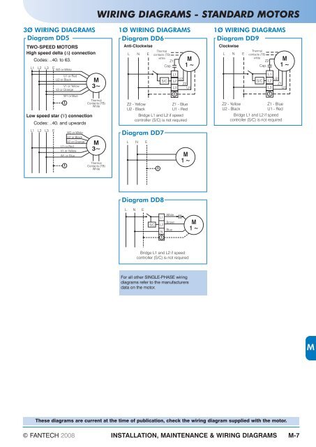
<strong>WIRING</strong> <strong>DIAGRAMS</strong> - <strong>STANDARD</strong> <strong>MOTORS</strong><br />
3Ø <strong>WIRING</strong> <strong>DIAGRAMS</strong> 1Ø <strong>WIRING</strong> <strong>DIAGRAMS</strong><br />
Diagram DD5<br />
Diagram DD6<br />
TWO-SPEED <strong>MOTORS</strong><br />
High speed delta ( )<br />
connection<br />
L1<br />
E<br />
W2 or White<br />
U1 or Red<br />
U2 or Black<br />
V1 or Yellow<br />
V2 or Orange<br />
W1 or Blue<br />
Low speed star ( )<br />
connection<br />
L1<br />
Codes: ..40. to 63.<br />
L2<br />
L2<br />
L3<br />
Codes: ..40. and upwards<br />
L3<br />
E<br />
W2 or White<br />
U2 or Black<br />
V2 or Orange<br />
U1 or Red<br />
V1 or Yellow<br />
W1 or Blue<br />
M<br />
3~<br />
Thermal<br />
Contacts (TB)<br />
White<br />
M<br />
3~<br />
Thermal<br />
Contacts (TB)<br />
White<br />
Anti-Clockwise<br />
L N E<br />
Diagram DD7<br />
L N E<br />
Diagram DD8<br />
Thermal<br />
contacts (TB)<br />
white<br />
Z1 M<br />
Cap.<br />
For all other SINGLE-PHASE wiring<br />
diagrams refer to the manufacturers<br />
data on the motor.<br />
© FANTECH 2008 INSTALLATION, MAINTENANCE & <strong>WIRING</strong> <strong>DIAGRAMS</strong> M-7<br />
S/C<br />
L1<br />
L2<br />
L3<br />
1~<br />
U2<br />
Z2<br />
U1<br />
Z2 - Yellow Z1 - Blue<br />
U2 - Black U1 - Red<br />
Bridge L1 and L2 if speed<br />
controller (S/C) is not required<br />
L N E<br />
S/C<br />
L1<br />
L2<br />
N<br />
White<br />
Brown<br />
Blue<br />
M<br />
1~<br />
Bridge L1 and L2 if speed<br />
controller (S/C) is not required<br />
M<br />
1~<br />
1Ø <strong>WIRING</strong> <strong>DIAGRAMS</strong><br />
Diagram DD9<br />
Clockwise<br />
L N E<br />
Thermal<br />
contacts (TB)<br />
white<br />
Z2 M<br />
Cap.<br />
S/C<br />
L1<br />
L2<br />
L3<br />
1~<br />
U2<br />
Z1<br />
U1<br />
Z2 - Yellow Z1 - Blue<br />
U2 - Black U1 - Red<br />
Bridge L1 and L2 if speed<br />
controller (S/C) is not required<br />
These diagrams are current at the time of publication, check the wiring diagram supplied with the motor.<br />
M