FAKRA SMB RF Connectors Cable Connectors, PCB ... - Walcom
FAKRA SMB RF Connectors Cable Connectors, PCB ... - Walcom
FAKRA SMB RF Connectors Cable Connectors, PCB ... - Walcom

Create successful ePaper yourself
Turn your PDF publications into a flip-book with our unique Google optimized e-Paper software.
10<br />
RosenbergerHSD ®<br />
The situation improves dramatically if the<br />
balanced pair is fed in differential mode.<br />
The currents flowing on the wires of the<br />
differential line are of the same magnitude<br />
and opposite in sign. The sum current on<br />
the cable sheath is thus zero. This shows in<br />
an increase of the shielding attenuation by<br />
some 30 dB (!) compared to common<br />
mode.<br />
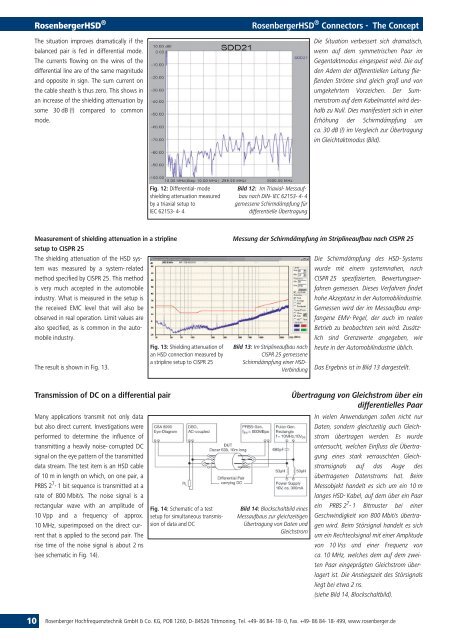
Measurement of shielding attenuation in a stripline<br />
setup to CISPR 25<br />
The shielding attenuation of the HSD system<br />
was measured by a system- related<br />
method specified by CISPR 25. This method<br />
is very much accepted in the automobile<br />
industry. What is measured in the setup is<br />
the received EMC level that will also be<br />
observed in real operation. Limit values are<br />
also specified, as is common in the automobile<br />
industry.<br />
Fig. 13: Shielding attenuation of<br />
an HSD connection measured by<br />
a stripline setup to CISPR 25<br />
The result is shown in Fig. 13.<br />
Transmission of DC on a differential pair<br />
Many applications transmit not only data<br />
but also direct current. Investigations were<br />
performed to determine the influence of<br />
transmitting a heavily noise- corrupted DC<br />
signal on the eye pattern of the transmitted<br />
data stream. The test item is an HSD cable<br />
of 10 m in length on which, on one pair, a<br />
PRBS 2 7 - 1 bit sequence is transmitted at a<br />
rate of 800 Mbit/s. The noise signal is a<br />
rectangular wave with an amplitude of<br />
10 Vpp and a frequency of approx.<br />
10 MHz, superimposed on the direct current<br />
that is applied to the second pair. The<br />
rise time of the noise signal is about 2 ns<br />
(see schematic in Fig. 14).<br />
Fig. 12: Differential- mode<br />
shielding attenuation measured<br />
by a triaxial setup to<br />
IEC 62153- 4- 4<br />
Fig. 14: Schematic of a test<br />
setup for simultaneous transmission<br />
of data and DC<br />
RosenbergerHSD ® <strong>Connectors</strong> - The Concept<br />
Bild 12: Im Triaxial- Messaufbau<br />
nach DIN- IEC 62153- 4- 4<br />
gemessene Schirmdämpfung für<br />
differentielle Übertragung<br />
Die Situation verbessert sich dramatisch,<br />
wenn auf dem symmetrischen Paar im<br />
Gegentaktmodus eingespeist wird. Die auf<br />
den Adern der differentiellen Leitung fließenden<br />
Ströme sind gleich groß und von<br />
umgekehrtem Vorzeichen. Der Summenstrom<br />
auf dem Kabelmantel wird deshalb<br />
zu Null. Dies manifestiert sich in einer<br />
Erhöhung der Schirmdämpfung um<br />
ca. 30 dB (!) im Vergleich zur Übertragung<br />
im Gleichtaktmodus (Bild).<br />
Messung der Schirmdämpfung im Striplineaufbau nach CISPR 25<br />
Bild 13: Im Striplineaufbau nach<br />
CISPR 25 gemessene<br />
Schirmdämpfung einer HSD-<br />
Verbindung<br />
Bild 14: Blockschaltbild eines<br />
Messaufbaus zur gleichzeitigen<br />
Übertragung von Daten und<br />
Gleichstrom<br />
Die Schirmdämpfung des HSD- Systems<br />
wurde mit einem systemnahen, nach<br />
CISPR 25 spezifizierten, Bewertungsverfahren<br />
gemessen. Dieses Verfahren findet<br />
hohe Akzeptanz in der Automobilindustrie.<br />
Gemessen wird der im Messaufbau empfangene<br />
EMV- Pegel, der auch im realen<br />
Betrieb zu beobachten sein wird. Zusätzlich<br />
sind Grenzwerte angegeben, wie<br />
heute in der Automobilindustrie üblich.<br />
Das Ergebnis ist in Bild 13 dargestellt.<br />
Übertragung von Gleichstrom über ein<br />
differentielles Paar<br />
In vielen Anwendungen sollen nicht nur<br />
Daten, sondern gleichzeitig auch Gleichstrom<br />
übertragen werden. Es wurde<br />
untersucht, welchen Einfluss die Übertragung<br />
eines stark verrauschten Gleichstromsignals<br />
auf das Auge des<br />
übertragenen Datenstroms hat. Beim<br />
Messobjekt handelt es sich um ein 10 m<br />
langes HSD- Kabel, auf dem über ein Paar<br />
ein PRBS 2 7 - 1 Bitmuster bei einer<br />
Geschwindigkeit von 800 Mbit/s übertragen<br />
wird. Beim Störsignal handelt es sich<br />
um ein Rechtecksignal mit einer Amplitude<br />
von 10 Vss und einer Frequenz von<br />
ca. 10 MHz, welches dem auf dem zweiten<br />
Paar eingeprägten Gleichstrom überlagert<br />
ist. Die Anstiegszeit des Störsignals<br />
liegt bei etwa 2 ns.<br />
(siehe Bild 14, Blockschaltbild).<br />
Rosenberger Hochfrequenztechnik GmbH & Co. KG, POB 1260, D- 84526 Tittmoning, Tel. +49- 86 84- 18- 0, Fax. +49- 86 84- 18- 499, www.rosenberger.de