EFFECT OF 'OVERLAPPING' VOLTAGE CONTACTS IN PLANAR ...
EFFECT OF 'OVERLAPPING' VOLTAGE CONTACTS IN PLANAR ...
EFFECT OF 'OVERLAPPING' VOLTAGE CONTACTS IN PLANAR ...

You also want an ePaper? Increase the reach of your titles
YUMPU automatically turns print PDFs into web optimized ePapers that Google loves.
20<br />
Venfmatlon of the model<br />
In order to venfy the model, the response of five one-sided PHTs of<br />
vmous configurations 1s measured m homogeneous fields induced by a psur<br />
of Helmholtz coils and m mhomogeneous fields induced by a current con-<br />
ductor The PHTs consisted of a vacuum-evaporated permalloy stnpe having<br />
length I = 11 mm, urldth zu = 2 mm and thickness t = 50 nm The mtrmslc<br />
properties such as magnetoreslstance Ap/p and anrsotropy field HK of the<br />
permalloy stnpe are measured by standard techmques The various conflg-<br />
uratlons are defined by the alummlum contacts (thickness t = 1 pm) Four<br />
PHTs have a sensor length 1 = 0 8 mm of which the overlap depths vary from<br />
0.1 to 1.5 mm. Because of the large value of w/l (= 2 5) the Hall voltage<br />
IS built up mainly at the edges [ 3 1, so a very large degree of dlscretlzatlon<br />
(m the width) IS necessary to obtam good accuracy W&h the chosen degree<br />
of dlscretlzatlon (210 node-points) there s still a reasonable agreement<br />
between the computed results and the expenmental ones In order to obtam<br />
a better accuracy with the same number of node-pomts, a PHT 1s taken<br />
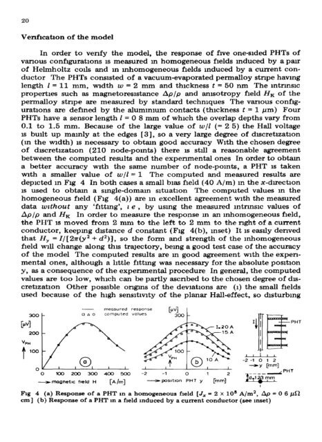
with a smaller value of w/l = 1 The computed and measured results are<br />
depicted m Fig 4 In both cases a small bias field (40 A/m) m the x-dlrectlon<br />
IS used to obtam a smgle-domam sltuatlon The computed values m the<br />
homogeneous field (Fig 4(a)) are m excellent agreement with the measured<br />
data wrthout any ‘flttmg’, z e , by using the measured mtrmslc values of<br />
AP/P and HK In order to measure the response m an mhomogeneous field,<br />
the PHT is moved from 2 mm to the left to 2 mm to the right of a current<br />
conductor, keepmg distance d constant (Fig 4(b), Inset) It 1s easily derived<br />
that HY = I/[ 27r(y* + d*)j, so the form and strength of the mhomogeneous<br />
field will change along this tralectory, bemg a good test case of the accuracy<br />
of the model The computed results are m good agreement mth the expen-<br />
mental ones, although a little flttmg was necessary for the absolute posltlon<br />
y, as a consequence of the expenmental procedure In general, the computed<br />
values are too low, which can be partly ascribed to the chosen degree of dls-<br />
cretizatlon Other possible omgms of the devlatlons are (1) the small fields<br />
used because of the high sensltlvlty of the planar Hall-effect, so disturbing<br />
300-<br />
- measured response<br />
0*0 computed voIucs<br />
0 IO0 200 300 400 5cxl -2 -1 0 1 2<br />
emagnetlc frsld l-i CA /ml<br />
-posltlon PHT y Cm4<br />
-2 -1 0 1 2<br />
-Y rmml<br />
Frg 4 (a) Response of a PHT m a homogeneous field [J, = 2 x 10’ A/m’, Ap = 0 6 pa<br />
cm] (b) Response of a PHT m a field induced by a current conductor (see mset)<br />
PHT