USER INSTRUCTIONS - Flowserve
USER INSTRUCTIONS - Flowserve
USER INSTRUCTIONS - Flowserve

You also want an ePaper? Increase the reach of your titles
YUMPU automatically turns print PDFs into web optimized ePapers that Google loves.
6<br />
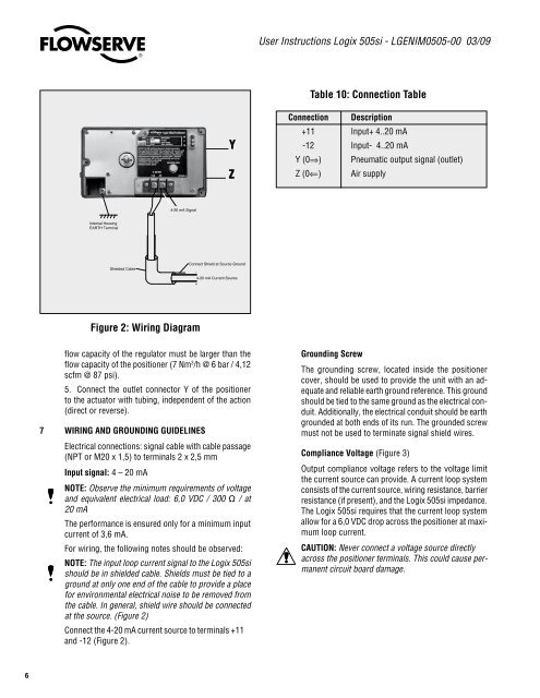
Internal Housing<br />
EARTH Terminal<br />
Shielded Cable<br />
®<br />
Figure 2: Wiring Diagram<br />
flow capacity of the regulator must be larger than the<br />
flow capacity of the positioner (7 Nm3 /h @ 6 bar / 4,12<br />
scfm @ 87 psi).<br />
5. Connect the outlet connector Y of the positioner<br />
to the actuator with tubing, independent of the action<br />
(direct or reverse).<br />
7 WiRing AnD gROUnDing gUiDELinES<br />
Electrical connections: signal cable with cable passage<br />
(NPT or M20 x 1,5) to terminals 2 x 2,5 mm<br />
input signal: 4 – 20 mA<br />
4-20 mA Signal<br />
nOTE: Observe the minimum requirements of voltage<br />
and equivalent electrical load: 6,0 VDC / 300 Ω / at<br />
20 mA<br />
The performance is ensured only for a minimum input<br />
current of 3,6 mA.<br />
For wiring, the following notes should be observed:<br />
nOTE: The input loop current signal to the Logix 505si<br />
should be in shielded cable. Shields must be tied to a<br />
ground at only one end of the cable to provide a place<br />
for environmental electrical noise to be removed from<br />
the cable. In general, shield wire should be connected<br />
at the source. (Figure 2)<br />
Connect the 4-20 mA current source to terminals +11<br />
and -12 (Figure 2).<br />
Y<br />
Z<br />
Connect Shield at Source Ground<br />
-<br />
4-20 mA Current Source<br />
+<br />
User Instructions Logix 505si - LGENIM0505-00 03/09<br />
Table 10: Connection Table<br />
Connection Description<br />
+11 Input+ 4..20 mA<br />
-12 Input- 4..20 mA<br />
Y (0⇒) Pneumatic output signal (outlet)<br />
Z (0⇐) Air supply<br />
grounding Screw<br />
The grounding screw, located inside the positioner<br />
cover, should be used to provide the unit with an adequate<br />
and reliable earth ground reference. This ground<br />
should be tied to the same ground as the electrical conduit.<br />
Additionally, the electrical conduit should be earth<br />
grounded at both ends of its run. The grounded screw<br />
must not be used to terminate signal shield wires.<br />
Compliance Voltage (Figure 3)<br />
Output compliance voltage refers to the voltage limit<br />
the current source can provide. A current loop system<br />
consists of the current source, wiring resistance, barrier<br />
resistance (if present), and the Logix 505si impedance.<br />
The Logix 505si requires that the current loop system<br />
allow for a 6,0 VDC drop across the positioner at maximum<br />
loop current.<br />
CAUTiOn: Never connect a voltage source directly<br />
across the positioner terminals. This could cause permanent<br />
circuit board damage.