
You also want an ePaper? Increase the reach of your titles
YUMPU automatically turns print PDFs into web optimized ePapers that Google loves.
Subject to technical changes<br />
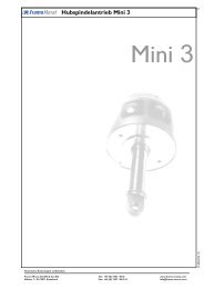
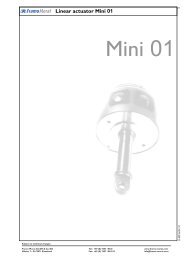
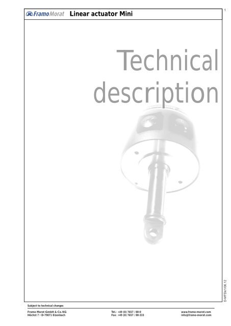
<strong>Linear</strong> <strong>actuator</strong> <strong>Mini</strong><br />
Technical<br />
description<br />
<strong>Framo</strong> <strong>Morat</strong> GmbH & Co. KG Tel.: +49 (0) 7657 / 88-0 www.framo-morat.com<br />
Höchst 7 • D-79871 Eisenbach Fax: +49 (0) 7657 / 88-333 info@framo-morat.com<br />
1<br />
D-MTDe1/06.12
2<br />
Technical description<br />
1.Design<br />
Subject to technical changes<br />
<strong>Linear</strong> <strong>actuator</strong> <strong>Mini</strong><br />
<strong>Framo</strong> linear <strong>actuator</strong>s are electromechanical drives which convert the rotating motion of the integrated electric<br />
motor into a linear forward or backward motion.<br />
<strong>Framo</strong> <strong>actuator</strong>s are primarily designed for industrial use. They are particularly robust and equipped with many<br />
safety standards. All installation positions are permissible.<br />
Special technical features are:<br />
Complete stainless steel housing (for type <strong>Mini</strong> 0, 01 and 1) which protects all mechanical and electrical parts<br />
(including terminal board). Only the connecting cables and the movable piston rod needs to be retracted.<br />
2. Piston rod<br />
The stainless steel piston rod is ground (except for <strong>Mini</strong> 3).<br />
The piston rod is not locked to prevent torsion. The customer must provide a locking facility with the part that is<br />
moved.<br />
Radial forces are generally not allowed.<br />
3. Motors<br />
The built-in electric motor has a hollow rotor shaft which permits the lifting spindle and the piston rod to be guided<br />
through it and therefore allows particularly short dimensions.<br />
Depending on the size, the motors can be delivered with three-phase, single-phase or direct current (special voltage<br />
on request). With the exception of the direct current motor, all motors are fitted with a thermal protection switch<br />
(trigger temperature +125°C. The motor winding is ISO class B. Standard protection class: IP 54. The three-phase<br />
motors can be connected to 3 x 230 or 3 x 400 V AC.<br />
3.1 DC <strong>actuator</strong>s<br />
Separate power tables are available for DC <strong>actuator</strong>s (only <strong>Mini</strong> 0).<br />
If the DC motor operates as an individual unit, a suitable EMC interference suppressor shall be provided close to the<br />
motor terminal drive. For unit installation, the unit has to be suppressed.<br />
For this reason direct interference elimination is not always necessary and the interference suppressor is not<br />
located in the drive, therefore the customer has to plan for this possible requirement.<br />
4. Duty cycle<br />
The indicated duty cycles relate to a maximum load time of 10 minutes, a maximum ambient temperature of 40°C<br />
and a maximum installation height of 1000 m above sea level.<br />
5. Gears, stroke lengths<br />
Implementation without gears or the installation of 1- to 3-stage planetary gears allows the selection of different<br />
stroke speeds for every type (0.5 to 136 mm/s). Depending on the type, special travel lengths of 10 to 800 mm are<br />
possible.<br />
6. Spindle<br />
<strong>Framo</strong> <strong>Mini</strong> <strong>actuator</strong>s with a rolled acme lead screw are predominantly dynamically self-locking.<br />
<strong>Framo</strong> <strong>Morat</strong> GmbH & Co. KG Tel.: +49 (0) 7657 / 88-0 www.framo-morat.com<br />
Höchst 7 • D-79871 Eisenbach Fax: +49 (0) 7657 / 88-333 info@framo-morat.com
7. Limit switches<br />
Subject to technical changes<br />
<strong>Linear</strong> <strong>actuator</strong> <strong>Mini</strong><br />
A limit switch is incorporated for each stroke-end position. The <strong>Mini</strong> 01 up to <strong>Mini</strong> 3 are also equipped with a safety<br />
limit switch (forced separator) which protects the <strong>actuator</strong> against destruction in case of faulty wiring or if a limit switch<br />
fails. The limit switches are installed in a fixed position and cannot be adjusted.<br />
8. Brake<br />
At stroke speeds of more than 20 mm/s, three-phase and single-phase <strong>actuator</strong>s should be equipped with a brake<br />
because of their tendency to overrun (DC <strong>actuator</strong>s see performance table notes).<br />
We also recommend that a brake is installed if the drive has a spindle that is not self-locking and if the demands on<br />
disconnection accuracy are exacting. A magnetic-electric single-disc brake is available for all sizes.<br />
9. Connection cables<br />
The standard <strong>actuator</strong>s are supplied with external connection cables (1m length). Longer or shielded cables are<br />
available. Custom connection cables on request.<br />
10. Fixing options, connection heads<br />
Flange, foot and attachment bolts can be supplied in addition to standard attachment configuration A (attachment<br />
eye to eye). The drive can also be delivered with different connection heads (see dimensional drawings).<br />
11. Paint coating (only <strong>Mini</strong> 2 and 3)<br />
The standard drive housing (tubular steel) is sprayed with a special acrylic resin lacquer (RAL 7031, bluish grey)<br />
which is also suitable as primer for other lacquers (artificial or acrylic).<br />
12. Reliability and quality assurance<br />
Every <strong>actuator</strong> is produced according to order and tested under nominal load conditions. A proven modular system<br />
makes it possible to produce a large number of different models and to adapt them to customer requirements. All<br />
individual parts and sub-assemblies are generally kept in stock.<br />
13. Conditions of use<br />
The conditions of <strong>actuator</strong> use prohibit the movement of loads whereby persons can be directly or<br />
indirectly endangered.<br />
The application of <strong>actuator</strong>s in equipment intended to transport passengers is not permitted without first<br />
consulting the manufacturer (or responsible representative).<br />
In this context we refer to EU Machinery Directive 98 / 37 / EC and the Act on Technical Equipment<br />
(Equipment Safety Act) where the user is responsible for the implementation of "protective<br />
guards/barriers" to prevent touching (crushing hazard) during operation.<br />
This also applies for the application of <strong>actuator</strong>s with suspended loads where persons can be<br />
endangered.<br />
<strong>Framo</strong> <strong>Morat</strong> GmbH & Co. KG Tel.: +49 (0) 7657 / 88-0 www.framo-morat.com<br />
Höchst 7 • D-79871 Eisenbach Fax: +49 (0) 7657 / 88-333 info@framo-morat.com<br />
3
4<br />
14. Safety option<br />
Subject to technical changes<br />
<strong>Linear</strong> <strong>actuator</strong> <strong>Mini</strong><br />
It is possible to bring the <strong>actuator</strong>s of size 01, 1 and 2 to a higher safety standard by using the force-dependent shutoff.<br />
Generally, enough safety features should be included when choosing the <strong>actuator</strong> size.<br />
15. Self-locking ability<br />
16. Options<br />
The self-locking ability depends on the spindle pitch, the surface quality of the spindle/nut, the sliding<br />
speed, lubrication and temperature. We distinguish between dynamic (out of motion) and static<br />
(stationary) self-locking.<br />
Vibrations can eliminate self-locking. A certain number of factors such as lubrication, sliding speed and<br />
load can also create such favorable sliding characteristics that the self-locking is negatively influenced.<br />
A theoretically self-locking spindle cannot therefore replace a brake. Therefore it is impossible to<br />
assume guarantee obligations regarding self-locking.<br />
Important: Self-locking is not intended to satisfy security-related characteristics!<br />
To minimize additional dangers, observe the usual care for technical products.<br />
The following options allow individual applications:<br />
1. IP 65 (water jet proof)<br />
2. Force-dependent shut-off (as protection for block movement or if a preset stroke force is exceeded except<br />
<strong>Mini</strong> 0 and <strong>Mini</strong> 3)<br />
3. Adjustable connection head (for small changes to the attachment position)<br />
4. Adjusting ring on piston rod (for simple retracting position adjustment)<br />
5. Brake (for precise switch-off and non-self-locking <strong>actuator</strong>s)<br />
6. Integrated helical potentiometer (for travel monitoring and/or position control)<br />
7. Rotary pulse encoder (for digital pulse processing for position and speed control)<br />
8. Different fixing possibilities (installation conditions can be taken into account)<br />
9. Humidification seal coating of rotor and stator and/or condensation hole (if there is danger of condensation).<br />
10. Explosion proof according to directive 94 / 9 / EG (ATEX 95)<br />
11. Connection cable motor and/or helical potentiometer shielded (for frequency converter operation etc.)<br />
<strong>Framo</strong> <strong>Morat</strong> GmbH & Co. KG Tel.: +49 (0) 7657 / 88-0 www.framo-morat.com<br />
Höchst 7 • D-79871 Eisenbach Fax: +49 (0) 7657 / 88-333 info@framo-morat.com
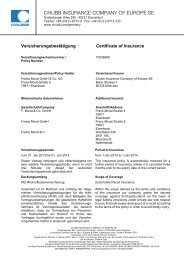
Limit switches<br />
Subject to technical changes<br />
<strong>Linear</strong> <strong>actuator</strong> <strong>Mini</strong><br />
2 limit switches (two-way contact) arranged below 45° to each other.<br />
Force separated safety limit switch (not for <strong>Mini</strong> 0) lying in-between<br />
Switching jack<br />
'Extended' position<br />
Piston rod<br />
System advantages:<br />
Terminal board with<br />
Connector<br />
Housing<br />
• No continuous contact of limit switch and piston rod<br />
• Improved insulation and more stability, no switching grooves<br />
• End of stroke damping through installed spring<br />
• Better control of the piston rod<br />
Adjusting ring for retracted position<br />
Grub screws Adjusting ring<br />
Front cover<br />
Switching jack<br />
'Retracting' position<br />
<strong>Framo</strong> <strong>Morat</strong> GmbH & Co. KG Tel.: +49 (0) 7657 / 88-0 www.framo-morat.com<br />
Höchst 7 • D-79871 Eisenbach Fax: +49 (0) 7657 / 88-333 info@framo-morat.com<br />
5