Integrated Gasification Combined Cycle (IGCC) - National Energy ...
Integrated Gasification Combined Cycle (IGCC) - National Energy ...
Integrated Gasification Combined Cycle (IGCC) - National Energy ...

You also want an ePaper? Increase the reach of your titles
YUMPU automatically turns print PDFs into web optimized ePapers that Google loves.
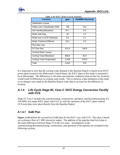
<strong>Gasification</strong> Losses<br />
Table A-18: <strong>IGCC</strong> Water Loss by Function<br />
Function gpm Gal/MWh Electricity<br />
Water Lost in <strong>Gasification</strong> Shift 158 18.2<br />
Ash Handling Blowdown 81.1 9.3<br />
Water with Slag 32 3.7<br />
Water loss in COS Hydrolysis 0.5 0.1<br />
Water Treatment Effluent 22.2 2.5<br />
Flue Gas Loss<br />
GT Flue Gas 912.6 104.8<br />
Cooling Water Losses<br />
Cooling Tower Blowdown 808.8 92.9<br />
Cooling Tower Evaporation 2,428 278.9<br />
Total 4,443 510<br />
Appendix: <strong>IGCC</strong>-LCA<br />
It is important to note that the cooling water demand in the Baseline Report is based on an <strong>IGCC</strong><br />
power plant located in the Midwestern United States; the <strong>IGCC</strong> plant in this study is assumed to<br />
be in Mississippi. The differences in elevation and ambient conditions between the two locations<br />
would result in differences in cooling water needs. This is noted as a data limitation in this study<br />
as no changes were made to the Baseline Report water data to account for the difference in<br />
location.<br />
A.1.4<br />
Life <strong>Cycle</strong> Stage #3, Case 2: <strong>IGCC</strong> <strong>Energy</strong> Conversion Facility<br />
with CCS<br />
Stage #3, Case 2 includes the commissioning, construction, operation, and decommissioning of a<br />
556-MWe net output <strong>IGCC</strong> plant with CCS; as with the operation of the <strong>IGCC</strong> plant without<br />
CCS most data were taken directly from the Baseline Report.<br />
A.1.4.1 GaBi Plan<br />
Figure A-16 defines the second level GaBi plan for the <strong>IGCC</strong> case with CCS. This plan is based<br />
on a reference flow of 1 MW electricity output. The addition of the pipeline third level plan is<br />
the main differences between Stage #3 in the two cases. Assumptions on the<br />
commissioning/decommissioning, construction, and operation of the pipeline are included in the<br />
following sections.<br />
42