- Page 1 and 2: MFEREX -150 FORTE (P&'ysaccharide-l
- Page 3 and 4: A New Eight-Cylinder Cadillac | Typ
- Page 5 and 6: periodic vibration or thrashing whi
- Page 7 and 8: SALON—Five-passenger Price 32080,
- Page 9 and 10: i '!•• Hi" MI MI ii, • -ii' i
- Page 11 and 12: kvoitrKSTKK SUNDAY TELEGRAM. SKPTKM
- Page 13 and 14: • 'from .,.1..- .-, -.. . .. VuMt
- Page 15 and 16: WW s^H , 0J?./2
- Page 17 and 18: IXDEX '~ _ ~" ~T» Table of Content
- Page 19 and 20: INDEX REAR AXLE Description of 69 I
- Page 21 and 22: 10 OPERATION AND GENERAL CARE OPERA
- Page 23 and 24: OPERATION AND GENERAL CARE 15 INSTR
- Page 25 and 26: IS OPE RAT IO X" A N D GENERAL CARE
- Page 27 and 28: OPERATION AND GENERAL CARE OPERATIO
- Page 29 and 30: 20 OPERATION AND GENERAL CARE CARE
- Page 31 and 32: 30 LUBRICATION The connecting rod b
- Page 33 and 34: CLUTCH THRUST BALL RACE. 18 LUBRICA
- Page 35 and 36: 38 LUBRICATION » I da in
- Page 37 and 38: 42 ADJUSTMENTS ADJUSTMENTS 43 ADJUS
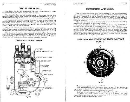
- Page 39: ADJUSTMENTS ADJUSTMENTS 3K IGNITION
- Page 43 and 44: ADDING WATER. ADJUSTMENTS The level
- Page 45 and 46: 58 ADJUSTMENTS The specific gravity
- Page 47: ADJUSTMENTS ADJUSTMENTS o:t STEERIN
- Page 50 and 51: c« AD.IUSTM.EMTS There are no adju
- Page 52 and 53: ADJUSTMENTS _ First loosen the bolt
- Page 54 and 55: 70 ADJUSTMENTS ADJUSTMENTS Tires. T
- Page 56 and 57: 80 ADJUSTMENTS ADDITIONAL SUGGESTIO
- Page 58 and 59: Hi ADJUSTMENTS Fig. VII Starting at
- Page 60: CADILLAC MOTOR CARS THE COAT OF ARM
- Page 63 and 64: Organization, Equipment and Methods
- Page 65 and 66: Iii this test, which was conducted
- Page 67 and 68: The Cadillac Eight-Cylinder V-type
- Page 69 and 70: Another advantage is that the openi
- Page 71 and 72: L^ac////ae G/g/if-CyA'/ic&r y ou)er
- Page 73 and 74: Each set of cylinders is cooled sep
- Page 75 and 76: Steering Mechanism The distinctive
- Page 77 and 78: Drive The drive is by special heat-
- Page 79 and 80: Bodies The artistic body designs wh
- Page 81 and 82: Finish Cadillacs have always been n
- Page 83 and 84: j Uei/en -y assertger i^a c fto t-*
- Page 85 and 86: \s>uh-y assenger ^bads/er l_. i- .-
- Page 87 and 88: \s>Aree-y^asse/iger V/c/or/d ^£P~
- Page 89 and 90: Oeibn-T-^sse/iger ^// /moi/s/zte CA
- Page 91 and 92:
Specifications in Brief ENGINE—Ei
- Page 93 and 94:
Type 53 Instructions For care and o
- Page 95 and 96:
CADILLAC "TYPE 53" INSTRUCTION BOOK
- Page 97 and 98:
CADILLAC "TYPE 53" INSTRUCTION BOOK
- Page 99 and 100:
CADILLAC "TYPE 5:;" INSTRUCTION BOO
- Page 101 and 102:
CADILLAC "TYPE 58" INSTRUCTION' BOO
- Page 103 and 104:
CADILLAC "TYPE 53" INSTRUCTION BOOK
- Page 105 and 106:
THROTTLE LEVER'- SPARK LEVER HORN S
- Page 107 and 108:
CADILLAC "TYPE 53" INSTRUCTION BOOK
- Page 109 and 110:
CADILLAC "TYPE 53" INSTRUCTION BOOK
- Page 111 and 112:
CADILLAC "TYPE 53" INSTRUCTION BOOK
- Page 113 and 114:
CADILLAC "TYPE 53" INSTRUCTION BOOK
- Page 115 and 116:
CADILLAC "TYPE 53" INSTRUCTION BOOK
- Page 117 and 118:
CADILLAC "TYPE 53" INSTRUCTION BOOK
- Page 119 and 120:
CADILLAC "TYPE 53" INSTRUCTION BOOK
- Page 121 and 122:
CADILLAC "TYPE 53" INSTRUCTION BOOK
- Page 123 and 124:
CADILLAC "TYPE 53" INSTRUCTION BOOK
- Page 125 and 126:
Part HI Adjustments
- Page 127 and 128:
CADILLAC "TYPE 53" INSTRUCTION BOOK
- Page 129 and 130:
CADILLAC "TYPE 53" INSTRUCTION BOOK
- Page 131 and 132:
CADILLAC "TYPE 53" INSTRUCTION BOOK
- Page 133 and 134:
CADILLAC "TYPE 53" INSTRUCTION BOOK
- Page 135 and 136:
CADILLAC "TYPE 53" INSTRUCTION BOOK
- Page 137 and 138:
CADILLAC "TYPE 53" INSTRUCTION BOOK
- Page 139 and 140:
CADILLAC "TYPE 53" INSTRUCTION BOOK
- Page 141 and 142:
CADILLAC "TYPE 53" INSTRUCTION BOOK
- Page 143 and 144:
CADILLAC "TYPE 53" INSTRUCTION BOOK
- Page 145 and 146:
CADILLAC "TYPE 53" INSTRUCTION BOOK
- Page 147 and 148:
CADILLAC "TYPE 53" INSTRUCTION BOOK
- Page 149 and 150:
CADILLAC "TYPE 53" INSTRUCTION BOOK
- Page 151 and 152:
CADILLAC -TYPE 53" INSTRUCTION BOOK
- Page 153 and 154:
CADILLAC "TYPE 53" INSTRUCTION BOOK
- Page 155 and 156:
CADILLAC "TYPE 53" INSTRUCTION BOOK
- Page 157 and 158:
CADILLAC "TYPE 53" INSTRUCTION BOOK
- Page 159 and 160:
CADILLAC "TYPE 53" INSTRUCTION BOOK
- Page 161 and 162:
CADILLAC "TYPE 53" INSTRUCTION BOOK
- Page 163 and 164:
CADILLAC "TYPE 53" INSTRUCTION BOOK
- Page 165 and 166:
CADILLAC "TYPE 53" INSTRUCTION BOOK
- Page 167 and 168:
CADILLAC "TYPE 53" INSTRUCTION BOOK
- Page 169 and 170:
CADILLAC "TYPE 53" INSTRUCTION BOOK
- Page 173 and 174:
Price List For Types 51-53-55-57 gS
- Page 175 and 176:
TO THE USER With more than a hundre
- Page 177 and 178:
KEY TO ABBREVIATIONS In many cases
- Page 179 and 180:
SPECIAL INSTRUCTIONS TO BE FOLLOWED
- Page 181 and 182:
CODIFIED SENTENCES CODE WORD Mail S
- Page 183 and 184:
2 PARTS LIST FOR TYPES 51-53-55-57
- Page 185 and 186:
PARTS LIST FOR TYPES 51-53-55-57 EN
- Page 187 and 188:
PARTS LIST FOR TYPES 51-53-55-57 EN
- Page 189 and 190:
PARTS LIST FOR TYPES 51-53-55-57 EN
- Page 191 and 192:
10 PARTS LIST FOR TYPES 51-53-55-57
- Page 193 and 194:
12 PARTS LIST FOR TYPES 51-53-55-57
- Page 195 and 196:
14 PARTS LIST FOR TYPES 51-53-55-57
- Page 197 and 198:
16 PARTS LIST FOR TYPES 51-53-55-57
- Page 199 and 200:
t fi PARTS LIST FOR TYPES 51-53-55-
- Page 201 and 202:
20 PARTS LIST FOR TYPES 51-53-55-57
- Page 203 and 204:
22 PARTS LIST FOR TYPES 51-53-55-57
- Page 205 and 206:
24 PARTS LIST FOR TYPES 51-53-55-57
- Page 207 and 208:
26 PARTS LIST FOR TYPES 51-53-55-57
- Page 209 and 210:
28 PARTS LIST FOR TYPES 51-53-55-57
- Page 211 and 212:
30 PARTS LIST FOR TYPES 51-53-55-57
- Page 213 and 214:
32 PARTS LIST FOR TYPES 51-53-55-57
- Page 215 and 216:
34 PARTS LIST FOR TYPES 51-53-55-57
- Page 217 and 218:
36 PARTS LIST FOR TYPES 51-53-55-57
- Page 219 and 220:
38 PARTS LIST FOR TYPES 51-53-55-57
- Page 221 and 222:
40 PARTS LIST FOR TYPES 51-53-55-57
- Page 223 and 224:
42 PARTS LIST FOR TYPES 51-53-55-57
- Page 225 and 226:
44 PARTS LIST FOR TYPES 51-53-55-57
- Page 227 and 228:
46 PARTS LIST FOR TYPES 51-53-55-57
- Page 229 and 230:
48 PARTS LIST FOR TYPES 51-53-55-57
- Page 231 and 232:
50 PARTS LIST FOR TYPES 51-53-55-57
- Page 233 and 234:
52 PARTS LIST FOR TYPES 51-53-55-57
- Page 235 and 236:
54 PARTS LIST FOR TYPES 51-53-55-57
- Page 237 and 238:
56 PARTS LIST FOR TYPES 51-53-55-57
- Page 239 and 240:
58 PARTS LIST FOR TYPES 51-53-55-57
- Page 241 and 242:
60 PARTS LIST FOR TYPES 51-53-55-57
- Page 243 and 244:
62 PARTS LIST FOR TYPES 51-53-55-57
- Page 245 and 246:
64 FARTS LIST FOR TYPES 51-53-/55-5
- Page 247 and 248:
66 PARTS LIST FOR TYPES 51-53-55-57
- Page 249 and 250:
68 PARTS LIST FOR TYPES 51-53-55-57
- Page 251 and 252:
70 PARTS LIST FOR TYPES 51-53-55-57
- Page 253 and 254:
72 PARTS LIST FOR TYPES 51-53-55-57
- Page 255 and 256:
74 PARTS LIST FOR TYPES 51-53-55-57
- Page 257 and 258:
76 PARTS LIST FOR TYPES 51-53-55-57
- Page 259 and 260:
78 PARTS LIST FOR TYPES 51-53-55-57
- Page 261 and 262:
80 PARTS LIST FOR TYPES 51-53-55-57
- Page 263 and 264:
82 PARTS LIST FOR TYPES 51-53-55-57
- Page 265 and 266:
84 PARTS LIST FOR TYPES 51-53-55-57
- Page 267 and 268:
86 PARTS LIST FOR TYPES 51-53-55-57
- Page 269 and 270:
S8 PARTS LIST FOR TYPES 51-53-55-57
- Page 271 and 272:
90 PARTS LIST FOR TYPES 51-53-55-57
- Page 273 and 274:
92 PARTS LIST FOR TYPES 51-53-55-57
- Page 275 and 276:
94 PARTS LIST FOR TYPES 51-53-55-57
- Page 277 and 278:
96 PARTS LIST FOR TYPES 51-53-55-57
- Page 279 and 280:
98 PARTS LIST FOR TYPES 51-53-55-57
- Page 281 and 282:
100 PARTS LIST FOR TYPES 51-53-55-5
- Page 283 and 284:
102 PARTS LIST FOR TYPES 51-53-55-5
- Page 285 and 286:
104 PARTS LIST FOR TYPES 51-53-55-5
- Page 287 and 288:
Code Word BADER CADER DADER KADER L
- Page 289 and 290:
108 PARTS LIST FOR TYPES 51-53-55-5
- Page 291 and 292:
110 PARTS LIST FOR TYPES 51-53-55-5
- Page 293 and 294:
112 PARTS LIST FOR TYPES 51-53-55-5
- Page 295 and 296:
114 PARTS LIST FOR TYPES 51-53-55-5
- Page 297 and 298:
116 PARTS LIST FOR TYPES 51-53-55-5
- Page 299 and 300:
3 £-2^.=^ Sea 4 11¾ 1)-^-511)¾¾
- Page 301 and 302:
120 PARTS LIST FOR TYPES 51-53-55-5
- Page 303 and 304:
122 PARTS LIST FOR TYPES 51-53-55-5
- Page 305 and 306:
124 PARTS LIST FOR TYPES 51-53-55-5
- Page 307 and 308:
126 PARTS LIST FOR TYPES 51-53-55-5
- Page 309 and 310:
128 PARTS LIST FOR TYPES 51-53-55-5
- Page 311 and 312:
130 PARTS LIST FOR TYPES 51-53-55-5
- Page 313 and 314:
132 PARTS LIST FOR TYPES 51-53-55-5
- Page 315 and 316:
134 PARTS LIST FOR TYPES 51-53-55-5
- Page 317 and 318:
136 PARTS LIST FOR TYPES 51-53-55-5
- Page 319 and 320:
138 PARTS LIST FOR TYPES 51-53-55-5
- Page 321 and 322:
140 PARTS PRICE LIST FOR TYPES 51-5
- Page 323 and 324:
142 PARTS LIST FOR TYPES 51-53-55-5
- Page 325 and 326:
144 PARTS LIST FOR TYPES 51-53-55-5
- Page 327 and 328:
146 PARTS LIST FOR TYPES 51-53-55-5
- Page 329 and 330:
148 PARTS LIST FOR TYPES 51-53-55-5
- Page 331 and 332:
150 PARTS LIST FOR TYPES 51-53-55-5
- Page 333 and 334:
152 PARTS LIST FOR TYPES 51-53-55-5
- Page 335 and 336:
154 PARTS LIST FOR TYPES 51-53-55-5
- Page 337 and 338:
156 PARTS LIST FOR TYPES 51-53-55-5
- Page 339 and 340:
158 PARTS LIST FOR TYPES 51-53-55-5
- Page 341 and 342:
100 PARTS LIST FOR TYPES 51-53-55-5
- Page 343 and 344:
162 PARTS LIST FOR TYPES 51-53-55-5
- Page 345 and 346:
164 PARTS LIST FOR TYPES 51-53-55-5
- Page 347 and 348:
106 PARTS LIST FOR TYPES 51-53-55-5
- Page 349 and 350:
1()8 PARTS LIST FOR TYPES 51-53-55-
- Page 351 and 352:
170 PARTS LIST FOR TYPES 51-53-55-5
- Page 353 and 354:
172 PARTS LIST FOR TYPES 51-53-55-5
- Page 355 and 356:
174 PARTS LIST FOR TYPES 51-53-55-5
- Page 357 and 358:
176 PARTS LIST FOR TYPES 51-53-55-5
- Page 359 and 360:
178 PARTS LIST FOR TYPES 51-53-55-5
- Page 361 and 362:
TYPE 51 SALON BODY, TOP AND WINDSHI
- Page 363 and 364:
182 PARTS LIST FOR TYPES 51-53-55-5
- Page 365 and 366:
WtmMimimMiiKilm^^ • l&^^'fdJF V ^
- Page 367 and 368:
TYPE 53 VICTORIA -.. r 1 JX- " S^sQ
- Page 369 and 370:
TYPE 55 TOURING TYPE 55 HI AETON TY
- Page 371 and 372:
TYPE 55 ROADSTER '..^ .«••, TY
- Page 373 and 374:
192 PARTS LIST FOR TYPES 51-53-55-5
- Page 375 and 376:
TYPE 55 LIMOUSINE TYPE 55 LANDAULET
- Page 377 and 378:
^H • 1 ^^^^^P^BB ^^^^* £^" •MP
- Page 379 and 380:
198 PARTS LIST FOR TYPES 51-53-55-5
- Page 381 and 382:
200 PARTS LIST FOR TYPES 51-53-55-5
- Page 383 and 384:
4 ^BB^^^^t HE t^H'li^P • BBBBBBMB
- Page 385 and 386:
204 PARTS LIST FOR TYPES 51-53-5.5-
- Page 387 and 388:
206 PARTS LIST FOR TYPES 51-53-55-5
- Page 389 and 390:
208 PARTS LIST FOR TYPES 51-53-55-7
- Page 391 and 392:
210 PARTS LIST FOR TYPES 51-53-55-5
- Page 393 and 394:
212 PARTS LIST FOR TYPES 51-53-55-5
- Page 395 and 396:
214 PARTS LIST FOR TYPES 51-53-55-5
- Page 397 and 398:
216 PARTS LIST FOR TYPES 51-53-55-5
- Page 399 and 400:
2IS PARTS LIST FOR TYPES 51-53-55-5
- Page 401 and 402:
220 INDEX—CONTINUED Name Page Cha
- Page 403 and 404:
222 INDEX—CONTINUED Name Page N N
- Page 405 and 406:
LIBRARY REFERENCE COPY Mircell-n NO
- Page 407 and 408:
Index of all Cadillac Models using
- Page 409 and 410:
INDEX OF ALL CADILLAC MODELS USING
- Page 411 and 412:
PIECE PARTS CATALOG 1 Motor Generat
- Page 413 and 414:
PIECE PARTS CATALOG 1 Motor Generat
- Page 415 and 416:
Motor Generator P a * e 2 THE DAYTO
- Page 417 and 418:
Motor Generator Page 4 THE DAYTON E
- Page 419 and 420:
PIECE PARTS CATALOG Page 1 20109 2
- Page 421 and 422:
PIECE PARTS CATALOG Piece Number 22
- Page 423 and 424:
44 Motor Generator PIECE PARTS CATA
- Page 425 and 426:
PIECE PARTS CATALOG Motor Generator
- Page 427 and 428:
PIECE PARTS CATALOG 44 Motor Genera
- Page 429 and 430:
PIECE PARTS CATALOG Motor Generator
- Page 431 and 432:
78 Motor Generator Page 2 THE DAYTO
- Page 433 and 434:
78 Motor Generator Page 4 THE DAYTO
- Page 435 and 436:
PIECE PARTS CATALOG 98 Motor Genera
- Page 437 and 438:
98 • Motor Generator PIECE PARTS
- Page 439 and 440:
98 Motor Generator PIECE PARTS CATA
- Page 441 and 442:
162 Motor Generator Page 2 No. 162
- Page 443 and 444:
162 Motor Generator Page 4 THE DAYT
- Page 445 and 446:
PIECE PARTS CATALOG 1007 Ignition S
- Page 447 and 448:
PIECE PARTS CATALOG Ignition Switch
- Page 449 and 450:
J 2 S — — DAYTON ENCW ? «N 1 L
- Page 451 and 452:
I'IKCH I'ARTS CATALOG Combination S
- Page 453 and 454:
1042 Combination Switch PIECE PARTS
- Page 455 and 456:
1045 Combination Switch THE DAYTON
- Page 457 and 458:
1061 Auto Horn Switch PIECE PARTS C
- Page 459 and 460:
PIECE PARTS CATALOG Combination Swi
- Page 461:
5312 Auto Horn Page 2 THE DAYTON EN
- Page 464 and 465:
20131 24388 24719 1 # •24720 2471
- Page 466 and 467:
£013.1 Z438& 24719 £4694 11371 11
- Page 469 and 470:
PIECE PARTS CATALOG 5206 " a S e v
- Page 471 and 472:
Distributor PIECE PARTS CATALOG Pag
- Page 473 and 474:
5166 Distributor PIECE PARTS CATALO
- Page 475 and 476:
THE DAYTON ENGINEERING LABORATORIES
- Page 477 and 478:
m 2 o en o H td C H O 7 m r ! 20173
- Page 479 and 480:
5105 Distributor Page 2 THE DAYTON
- Page 481 and 482:
5059 Distributor Page 2 THE DAYTON
- Page 483 and 484:
PIECE PARTS CATALOG 5055 Distributo
- Page 485 and 486:
PIECE PARTS CATALOG Distributor Pag
- Page 487 and 488:
Distributor PIECE PARTS CATALOG Pag
- Page 489 and 490:
PIECE PARTS CATALOG Ignition Coil P
- Page 491 and 492:
2092 Ignition Coil PIECE PARTS CATA
- Page 493 and 494:
PIECE PARTS CATALOG Ignition Coil P
- Page 495 and 496:
PIECE PARTS CATALOG Starting Switch
- Page 497 and 498:
PIECE PARTS CATALOG 1979 Ignition S
- Page 499 and 500:
1978 Ignition Switch PIECE PARTS CA
- Page 501 and 502:
combination awitcn Page 2 THE DAYTO
- Page 503 and 504:
1099 Combination Switch PIECE PARTS
- Page 505 and 506:
13324 ft 12142 = 53 g 26527 30635 2
- Page 507 and 508:
No. 1077 COMBINATION SWITCH Piece N
- Page 509 and 510:
1UD3 Combination Switch PIECE PARTS
- Page 511 and 512:
PIECE PARTS CATALOG 1069 Combinatio
- Page 513 and 514:
1062 Combination Switch Page 2 THE
- Page 515 and 516:
5401 Battery Box PIECE PARTS CATALO
- Page 517 and 518:
5401 Battery Box PIECE PARTS CATALO
- Page 519 and 520:
5401 Battery Box PIECE PARTS CATALO
- Page 521 and 522:
5401 Battery Box PIECE PARTS CATALO
- Page 523 and 524:
S401 Battery Box PIECE PARTS CATALO
- Page 525 and 526:
S401 Battery Box PIECE PARTS CATALO
- Page 527 and 528:
5404 Battery Box "'27 ' 2J939 No. 5
- Page 529 and 530:
5404 Battery Box Page 4 Piece Numbe
- Page 531 and 532:
PIECE PARTS CATALOG f 24552 y \ 2 0
- Page 533 and 534:
©a o 0 C •JOOG7 U034 20393 20791
- Page 535 and 536:
PIECE PARTS CATALOG 5506 Apparatus
- Page 537 and 538:
5661 Ignition Relay Page 2 THE DAYT
- Page 539 and 540:
5677 Ignition Relay Page 2 THE DAYT
- Page 541:
569Z Circuit Breaker Page 2 THE DAY
- Page 545 and 546:
5696 Circuit Breaker Page 2 THE DAY
- Page 547 and 548:
5705 Circuit Breaker Page 2 THE DAY
- Page 549 and 550:
5742 Circuit Breaker Page 2 THE DAY
- Page 551 and 552:
PIECE PARTS CATALOG 10678 Resistanc
- Page 553 and 554:
10726 Motor Clutch PIECE PARTS CATA