Parts List
Parts List
Parts List

You also want an ePaper? Increase the reach of your titles
YUMPU automatically turns print PDFs into web optimized ePapers that Google loves.
S70-200 SPL<br />
Page 2<br />
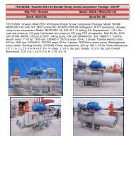
RWB II ROTARY SCREW COMPRESSOR UNIT<br />
SERVICE PARTS LIST<br />
HOW TO USE SERVICE PARTS LIST<br />
This Service <strong>Parts</strong> <strong>List</strong> is for standard Frick RWB II Plus, Rotary Screw Compressor Units, Models 60—856. Units built with<br />
special options, modifications, or conversions are not considered.This Service <strong>Parts</strong> <strong>List</strong> provides identification for detail parts by<br />
Figure and Index Number, Item Number and Description. To determine replacement part, locate item on Figure 1, 2, etc., note<br />
index number, refer to corresponding index number in parts list for item number and description. Quantity per assembly is located<br />
in QTY. column. Unit of measure is always "each" unless specified otherwise in Quantity column. When Ref. is in QTY. column,<br />
this means that the Item Number is for information only and is not necessarily a service replacement part. Contact Frick <strong>Parts</strong><br />
Department for more information. REV. (Revision) column tells the level of the engineering drawing parts were taken from. The<br />
P & I REF. column gives the reference number of the item as shown on the Piping and Instrumentation drawing. The Numerical<br />
<strong>Parts</strong> <strong>List</strong> can be used to locate a specific item in the Service <strong>Parts</strong> <strong>List</strong>.<br />
Abbreviations found in this manual include:<br />
A/R As Required SW Socket Weld<br />
HW Hand Wheel TSOC Thermosyphon Oil Cooler<br />
Ref. Reference WIL Weld-In-Line<br />
SC Seal Cap WCOC Water Cooled Oil Cooler<br />
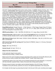
The Unit Data Plate listing model/serial number etc., is normally located to the left of the microprocessor, attached to<br />
the frame below the compressor motor.<br />
NOTE: PLEASE PROVIDE FRICK ORDER NUMBER, UNIT MODEL NUMBER, AND UNIT SERIAL NUMBER WHEN<br />
REQUESTING A QUOTATION OR PLACING AN ORDER. FAILURE TO INCLUDE THIS INFORMATION MAY DELAY<br />
PROCESSING OF YOUR REQUEST.<br />
TABLE OF CONTENTS<br />
Figure 1. General Arrangement, Typical. ...................................................... 4<br />
Figure 2. Screw Compressor, Typical. ........................................................... 6<br />
Figure 3. Oil Separator, Typical. .................................................................... 8<br />
Figure 4. Oil Filter, Standard, Typical. .......................................................... 12<br />
Figure 5. Dual Oil Filter, Typical. .................................................................. 13<br />
Figure 6. Oil Filter, Standard, Current. ........................................................ 14<br />
Figure 7. Dual Oil Filter, Standard, Current. ................................................ 16<br />
Figure 8. Piping and Instrumentation, Typical. ............................................ 18<br />
Figure 9. Prelube Oil Pump Piping, Typical. ............................................... 22<br />
Figure 10. Oil Cooler Piping, WCOC and TSOC, Typical. ........................... 26<br />
Figure 11. Oil Cooler Piping, WCOC and TSOC, Current. .......................... 32<br />
Figure 12. Full-Lube/Full-Cycling Oil Pump Piping, Typical. ...................... 34<br />
Figure 13. Liquid Injection Piping, Typical. ................................................. 38<br />
Figure 14. Liquid Injection with Oil Pump, Current. .................................... 42<br />
Figure 15. 4" Multivalve ............................................................................... 46<br />
Figure 16. 5"—8" Multivalve ........................................................................ 48<br />
Figure 17. 10" and 14" Multivalve ............................................................... 52<br />
Figure 18. 4 — 8" Multivalve, Current (Danfoss) ........................................ 56<br />
Figure 19. 3" and 4" Discharge Stop/Check Valve (Frick). .......................... 58<br />
Figure 20. 5"—8" Discharge Stop/Check Valve (Frick). .............................. 60<br />
Figure 21. 3"— 6" Discharge Stop Valve (Gram). ....................................... 64<br />
Figure 22. 8 & 10" Discharge Stop Valve (Gram/Frick). .............................. 68<br />
Figure 23. Discharge Stop/Check Valve, Current (Danfoss). ..................... 70<br />
Figure 24. Discharge Stop/Check Valve (Gram). ........................................ 72<br />
Figure 25. Economizer Kit. .......................................................................... 73<br />
Figure 26. Transducer Manifold Assembly. ................................................. 74<br />
Figure 27. Drive Coupling, Models 60—399 .............................................. 75<br />
Figure 28. Drive Coupling, Models 177—270 ............................................ 77<br />
Figure 29. Drive Coupling, Models 316—676. ........................................... 77<br />
Figure 30. Drive Coupling, Models 496—856. ........................................... 78<br />
Figure 31. Microprocessor Control Center (Single Box). ........................... 80<br />
Figure 32. Microprocessor Control Center (with Junction Box). ................. 82<br />
Figure 33. Junction Box Assembly. ............................................................. 84<br />
Figure 34. Quantum Control Panel, Typical. ............................................ 86<br />
Figure 35. Quantum Power Supply Identification. ...................................... 88<br />
DISPLAY ASSEMBLY COMPONENT REPLACEMENT GUIDE ................. 88<br />
COMPRESSOR PORT LOCATION LEGEND ............................................. 89<br />
Figure 36. 163/193mm Compressor Ports Locations ................................. 90<br />
Figure 37. 233mm Compressor Ports Locations ........................................ 91<br />
Figure 38. 283mm Compressor Ports Locations ........................................ 92<br />
Figure 39. 355mm Compressor Ports Locations ........................................ 93<br />
FRICK FLANGE GASKETS ......................................................................... 94<br />
FRICK BLUE PAINT .................................................................................... 94<br />
FRICK COMPRESSOR OILS ...................................................................... 94<br />
MISCELLANEOUS TUBING AND CONNECTORS .................................... 95<br />
NUMERICAL PARTS LIST .......................................................................... 96