Network Camera - Sony
Network Camera - Sony
Network Camera - Sony

Create successful ePaper yourself
Turn your PDF publications into a flip-book with our unique Google optimized e-Paper software.
How to install the camera<br />
1, 2<br />
3, 4<br />
6<br />
7<br />
8, 9<br />
Fall-prevention<br />
wire<br />
<strong>Camera</strong><br />
10, 11<br />
12<br />
13, 14<br />
Nuts<br />
Screws<br />
Wire bracket<br />
Bolts (3)<br />
Bolt<br />
Bolts (2)<br />
Bolts (3)<br />
Top unit<br />
Top unit<br />
Top unit<br />
Top unit<br />
Top sunshades<br />
Top sunshade<br />
Screw<br />
Mounting arm<br />
(not supplied)<br />
Bolt<br />
Wire-fixing belt<br />
Coupling<br />
Top unit<br />
Bolts (2)<br />
Waterproof covers (3)<br />
<strong>Camera</strong><br />
Align the<br />
trianglar marks<br />
Aligh the<br />
Trianglar<br />
marks<br />
<br />
<br />
<br />
How to install the wireless LAN<br />
2<br />
3<br />
4<br />
5<br />
Installation<br />
Notes<br />
The mounting arm (not supplied) to which the device is attached should have<br />
fixing screws of NPT 11/2”.<br />
When you install the camera, make sure you do not damage or spoil the dome<br />
cover.<br />
Ensure that the device is level, with the dome cover facing down.<br />
The lens zoom and angle may result in a blurred or inclined image within the<br />
range above the line of the dome cover ( a).<br />
Warning<br />
If installing the camera in high location, such as high wall, entrust the<br />
installation to a professional contractor or service personnel.<br />
The camera should be securely installed on a location strong enough to<br />
support the weight of the camera and the mounting arm. Otherwise, the<br />
camera and mounting arm may fall and cause serious injury.<br />
For the fall-prevention of the camera, make sure to use the wire rope.<br />
If the bolts are attached loosely or loosen, the camera and parts may fall. There<br />
may also be a risk of water leakage. Make sure to tighten the bolts and screws<br />
so that they will not loosen.<br />
Check the camera is attached securely, the screws, etc. are not loosened<br />
periodically, at the least once a year. Depending on the usage conditions,<br />
periodic inspections should be conducted more frequently.<br />
How to Install<br />
Hiding cover<br />
O-ring<br />
Washer<br />
Nut<br />
Washer<br />
Inner cable of<br />
the Antenna<br />
Cable Kit<br />
(optional)<br />
Card slot<br />
5-pin 9-pin<br />
Connector Connector<br />
MMCX<br />
connector<br />
a<br />
LAN<br />
Top unit<br />
Wireless Card<br />
Audio<br />
Output<br />
Top unit<br />
Top unit<br />
MMCX connector<br />
Wireless Card (optional)<br />
Mic<br />
Input<br />
ø238 (9 3 / 8)<br />
<strong>Camera</strong><br />
Video To 24 V<br />
Output AC<br />
Before installation<br />
Referring to the installation manual of the mounting arm (not supplied), drill the<br />
required holes for the mounting screws and the connection cable. Then install<br />
the mount arm in advance.<br />
344 (13 5 /8)<br />
Unit: mm (inches)<br />
<br />
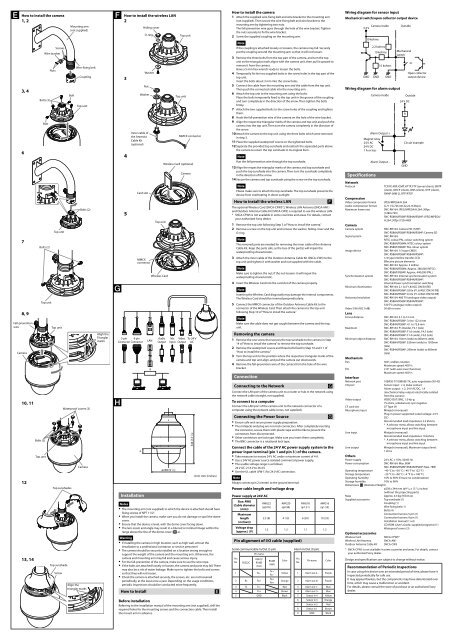
How to install the camera<br />
1 Attach the supplied wire-fixing belt and wire bracket to the mounting arm<br />
(not supplied). Then secure the wire-fixing belt and wire bracket to the<br />
mounting arm by tightening two nuts.<br />
The fall-prevention wire goes through the hole of the wire bracket. Tighten<br />
the nuts securely to fix the wire bracket.<br />
2 Screw the supplied coupling on the mounting arm.<br />
Note<br />
If the coupling is attached loosely or loosens, the camera may fall. Securely<br />
put the coupling around the mounting arm so that it will not loosen.<br />
3 Remove the three bolts from the top part of the camera, and turn the top<br />
unit so the triangular mark aligns with the camera unit, then pull it upward to<br />
remove it from the camera.<br />
Have a 5 mm hex wrench ready to loosen the bolts.<br />
4 Temporarily fix the two supplied bolts in the screw holes in the top part of the<br />
top unit.<br />
Insert the bolts about 3 mm into the screw holes.<br />
5 Connect the cable from the mounting arm and the cable from the top unit.<br />
Then push the connected cable into the mounting arm.<br />
6 Attach the top unit to the mounting arm using the bolts.<br />
Place the bolts temporarily fixed to the top unit in the groove of the coupling<br />
and turn completely in the direction of the arrow. Then tighten the bolts<br />
firmly.<br />
7 Attach the two supplied bolts to the screw holes of the coupling and tighten<br />
them.<br />
8 Hook the fall-prevention wire of the camera on the hole of the wire bracket.<br />
9 Align the respective triangular marks of the camera and top unit and push the<br />
camera into the top unit. Then turn the camera completely in the direction of<br />
the arrow.<br />
10 Attach the camera to the top unit using the three bolts which were removed<br />
in step 3.<br />
11 Place the supplied waterproof covers on the tightened bolts.<br />
12 Separate the provided top sunshade and reattach the separated parts above<br />
the camera to return the top sunshade to its original form.<br />
Note<br />
Run the fall-prevention wire through the top sunshade.<br />
13 Align the respective triangular marks of the camera and top sunshade and<br />
push the top sunshade into the camera. Then turn the sunshade completely<br />
in the direction of the arrow.<br />
14 Secure the camera and top sunshade using the screw on the top sunshade.<br />
Note<br />
Please make sure to attach the top sunshade. The top sunshade prevents the<br />
device from overheating in direct sunlight.<br />
How to install the wireless LAN<br />
The optional Wireless Card (SNCA-CFW5*), Wireless LAN Antenna (SNCA-AN1)<br />
and Outdoor Antenna Cable Kit (SNCA-CW5) is required to use the wireless LAN.<br />
* SNCA-CFW5 is not available in some countries and areas. For details, contact<br />
your authorized <strong>Sony</strong> dealer.<br />
1 Remove the top unit following Step 3 of “How to install the camera.”<br />
2 Remove a screw on the top unit and remove the washer, hiding cover and the<br />
O-ring.<br />
<br />
Note<br />
The removed parts are needed for removing the inner cable of the Antenna<br />
Cable Kit. Keep the parts safe, as the loss of the part(s) will impair the<br />
waterproofing characteristic.<br />
3 Attach the inner cable of the Outdoor Antenna Cable Kit (SNCA-CW5) to the<br />
top unit and tighten it with washer and nut supplied with the cable.<br />
Note<br />
Make sure to tighten the nut; if the nut loosens it will impair the<br />
waterproofing characteristic.<br />
4 Insert the Wireless Card into the card slot of the camera properly.<br />
Note<br />
Inserting the Wireless Card diagonally may damage the internal components.<br />
The Wireless Card should be inserted perpendicularly.<br />
5 Connect the MMCX connector of the Outdoor Antenna Cable Kit to the<br />
connector of the Wireless Card. Then attach the camera to the top unit<br />
following Step 10 of “How to install the camera.”<br />
Note<br />
Make sure the cable does not get caught between the camera and the top<br />
unit.<br />
Removing the camera<br />
1 Remove the one screw that secures the top sunshade to the camera in Step<br />
14 of “How to install the camera” to remove the top sunshade.<br />
2 Remove the waterproof covers and three bolts fixed in Step 10 and 11 of<br />
“How to install the camera.”<br />
3 Turn the top unit to the position where the respective triangular marks of the<br />
camera and top unit align, and pull the camera out downwards.<br />
4 Remove the fall-prevention wire of the camera from the hole of the wire<br />
bracket.<br />
Connection<br />
Connecting to the <strong>Network</strong><br />
Connect the LAN port of the camera unit to a router or hub in the network using<br />
the network cable (straight, not supplied).<br />
To connect to a computer<br />
Connect the LAN port of the camera unit to the network connector of a<br />
computer using the network cable (cross, not supplied).<br />
<br />
<br />
<br />
<br />
Connecting the Power Source<br />
Ensure safe and secure power supply preparation.<br />
The minijacks and plug are non-lock connectors. After completely inserting<br />
the connector, secure them with plastic tape and the like to prevent the<br />
connectors from disconnected.<br />
Other connectors are lock type. Make sure you insert them completely.<br />
The BNC connector is a rotational lock type.<br />
Connect the cable of the 24 V AC power supply system to the<br />
power input terminal (pin 1 and pin 3 ) of the camera.<br />
Take measures to ensure 24 V AC under a maximum current of 4 A.<br />
Use a 24V AC power source isolated commercial power supply.<br />
The usable voltage range is as follows:<br />
24 V AC: 21.6 V to 26.4 V<br />
Use the UL cable (VW-1) for 24 V AC connection.<br />
Note<br />
Always connect pin 2 (center) to the ground terminal.<br />
Power cable length and voltage drop<br />
Power supply at 24V AC<br />
Size: AWG<br />
(Cable diameter<br />
(mm))<br />
Maximum<br />
length<br />
(m (feet))<br />
Voltage drop<br />
(approx.) (V)<br />
AWG22<br />
(φ0.76)<br />
AWG20<br />
(φ0.94)<br />
AWG18<br />
(φ1.21)<br />
AWG16<br />
(φ1.53)<br />
2.5 (8) 4 (13) 6 (20) 10 (33)<br />
1.2 1.2 1.1 1.2<br />
Pin alignment of I/O cable (supplied)<br />
Serial communicable In/Out (5 pin)<br />
Pin name<br />
Pin<br />
No.<br />
RS232C<br />
RS422/<br />
RS485<br />
(Full)<br />
RS485<br />
(Half)<br />
Color<br />
Alarm In/Out (9 pin)<br />
Pin<br />
No.<br />
Pin name<br />
<br />
<br />
Color<br />
1 Rx−<br />
Tx−/<br />
Rx−<br />
Yellow 1 Alarm out 2− Purple<br />
2 Rx Rx+<br />
Tx+/<br />
Rx+<br />
Orange 2 Alarm out 2+ Purple<br />
3 Tx Tx− Red 3 Alarm out 1− Blue<br />
4 Tx+ Brown 4 Alarm out 1+ Blue<br />
5 GND Black 5 Sensor in 4 Yellow<br />
6 Sensor in 3 Orange<br />
7 Sensor in 2 Red<br />
8 Sensor in 1 Brown<br />
9 GND Black<br />
Wiring diagram for sensor input<br />
Mechanical switch/open collector output device<br />
<strong>Camera</strong> inside<br />
3.3 V<br />
GND<br />
10 kohms<br />
2.2 kohms<br />
10 kohms<br />
GND<br />
10 kohms<br />
GND<br />
Wiring diagram for alarm output<br />
<strong>Camera</strong> inside<br />
Alarm Output +<br />
Magnet relay<br />
24 V AC<br />
24 V DC<br />
1 A or less<br />
Specifications<br />
<strong>Network</strong><br />
Protocol<br />
Compression<br />
Video compression format<br />
Audio compression format<br />
Maximum frame rate<br />
<strong>Camera</strong><br />
<strong>Camera</strong> system<br />
Signal system<br />
Image device<br />
Synchronisation system<br />
Minimum illumination<br />
Horizontal resolution<br />
Video S/N (AGC 0 dB)<br />
Lens<br />
Forcus distance<br />
Maximum<br />
Minimum object distance<br />
Mechanism<br />
Pan<br />
Tilt<br />
Interface<br />
<strong>Network</strong> port<br />
I/O port<br />
Video output<br />
CF card slot<br />
Microphone input<br />
Line input<br />
Line output<br />
Alarm Output –<br />
Outside<br />
Mechanical<br />
switch<br />
24 V DC<br />
R<br />
or<br />
Open collector<br />
output device<br />
Outside<br />
Circuit example<br />
GND<br />
TCP/IP, ARP, ICMP, HTTP, FTP (server/client), SMTP<br />
(client), DHCP (client), DNS (client), NTP (client),<br />
SNMP (MIB-2), RTP/RTCP<br />
JPEG/MPEG4/H.264<br />
G.711/G.726 (40,32,24,16 kbps)<br />
SNC-RH164: JPEG/MPEG4/H.264: 30fps<br />
(1280×720)<br />
SNC-RS86N/RS86P/RS84N/RS84P: JPEG/MPEG4/<br />
H.264: 30fps (720×480)<br />
SNC-RH164: <strong>Camera</strong> HD (720P)<br />
SNC-RS86N/RS86P/RS84N/RS84P: <strong>Camera</strong> SD<br />
SNC-RH164:<br />
NTSC colour/PAL colour switching system<br />
SNC-RS86N/RS84N: NTSC colour system<br />
SNC-RS86P/RS84P: PAL colour system<br />
SNC-RH164: 1/3 type CMOS<br />
SNC-RS86N/RS86P/RS84N/RS84P:<br />
1/4 type interline transfer CCD<br />
Effective picture elements<br />
SNC-RH164: Approx. 2 million<br />
SNC-RS86N/RS84N: Approx. 380,000 (NTSC)<br />
SNC-RS86P/RS84P: Approx. 440,000 (PAL)<br />
SNC-RH164: Internal synchronisation system<br />
SNC-RS86N/RS86P/RS84N/RS84P:<br />
Internal/Power synchronisation switching<br />
SNC-RH164: 2.1 lx (F1.8/AGC ON/50 IRE)<br />
SNC-RS86N/RS86P: 0.8 lx (F1.6/AGC ON/50 IRE)<br />
SNC-RS84N/RS84P: 0.4 lx (F1.4/AGC ON/50 IRE)<br />
SNC-RH164: 480 TV (analogue video output)<br />
SNC-RS86N/RS86P/RS84N/RS84P:<br />
530 TV (analogue video output)<br />
50 dB or more<br />
SNC-RH164: 5.1 to 51 mm<br />
SNC-RS86N/RS86P: 3.4 to 122.4 mm<br />
SNC-RS84N/RS84P: 4.1 to 73.8 mm<br />
SNC-RH164: F1.8(wide), F2.1 (tele)<br />
SNC-RS86N/RS86P: F1.6 (wide), F4.5 (tele)<br />
SNC-RS84N/RS84P: F1.4 (wide), F3.0 (tele)<br />
SNC-RH164: 10mm (wide) to 800mm (tele)<br />
SNC-RS86N/RS86P: 320mm (wide) to 1500mm<br />
(tele)<br />
SNC-RS84N/RS84P: 290mm (wide) to 800mm<br />
(tele)<br />
360°, endless rotation<br />
Maximum speed: 400°/s<br />
210° (with auto invert function)<br />
Maximum speed: 400°/s<br />
10BASE-T/100BASE-TX, auto negotiation (RJ-45)<br />
Sensor input : × 4, make contact<br />
Alarm output : × 2, 24 V AC/DC, 1 A<br />
(mechanical relay outputs electrically isolated<br />
from the camera)<br />
VIDEO OUT: BNC, 1.0 Vp-p,<br />
75 ohms, unbalanced, sync negative<br />
CF Type I/II<br />
Minijack (monaural)<br />
Plug-in-power supported (rated voltage: 2.5 V<br />
DC)<br />
Recommended load impedance 2.2 khoms<br />
* A selector menu allows switching between<br />
microphone input and line input<br />
Minijack (monaural)<br />
Recommended load impedance 10 kohms<br />
* A selector menu allows switching between<br />
microphone input and line input<br />
Minijack (monaural), Maximum output level:<br />
1 Vrms<br />
Others<br />
Power supply<br />
24 V AC ± 10%, 50/60 Hz<br />
Power consumption<br />
SNC-RH164: Max. 80W<br />
SNC-RS86N/RS86P/RS84N/RS84P: Max. 78W<br />
Operating temperature –40 °C to +50 °C (–40 °F to 122 °F)<br />
Storage temperature<br />
–20 °C to +60 °C (–4 °F to +140 °F)<br />
Operating humidity<br />
10% to 90% (Ensure no condensation)<br />
Storage humidity 10% to 90%<br />
Dimensions (Diameter/Height)<br />
ø238 x 344 mm (ø9 3 /8 x 13 5 /8 inches)<br />
(without the projecting parts)<br />
Mass<br />
Approx. 4.3 kg (9 lb 8 oz)<br />
Supplied accessories Top sunshade (1)<br />
Coupling (1)<br />
Wire fixing belt (1)<br />
Bolts (4)<br />
Connection harness 5-pin (1)<br />
Connection harness 9-pin (1)<br />
Installation manual (1 set)<br />
CD-ROM (User’s Guide, supplied programs) (1)<br />
Waterproof covers (3)<br />
Optional accessories<br />
Wireless Card<br />
Wireless LAN Antenna<br />
Outdoor Antenna Cable Kit<br />
SNCA-CFW5*<br />
SNCA-AN1<br />
SNCA-CW5<br />
* SNCA-CFW5 is not available in some countries and areas. For details, contact<br />
your authorized <strong>Sony</strong> dealer.<br />
Design and specifications are subject to change without notice.<br />
Recommendation of Periodic Inspections<br />
In case using this device over an extended period of time, please have it<br />
inspected periodically for safe use.<br />
It may appear flawless, but the components may have deteriorated over<br />
time, which may cause a malfunction or accident.<br />
For details, please consult the store of purchase or an authorized <strong>Sony</strong><br />
dealer.