Integrated IR Dome Camera
Integrated IR Dome Camera
Integrated IR Dome Camera

Create successful ePaper yourself
Turn your PDF publications into a flip-book with our unique Google optimized e-Paper software.
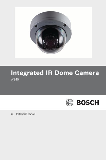
<strong>Integrated</strong> <strong>IR</strong> <strong>Dome</strong> <strong>Camera</strong><br />
WZ45<br />
en<br />
Installation Manual
<strong>Integrated</strong> <strong>IR</strong> <strong>Dome</strong> <strong>Camera</strong> Table of Contents | en 3<br />
Table of Contents<br />
1 Safety 5<br />
1.1 Safety Precautions 5<br />
1.2 Important Safety Instructions 5<br />
1.3 Important Notices 6<br />
1.4 FCC & ICES compliance 9<br />
1.5 Warranty / Limitation of Liability 12<br />
1.6 Contact Information 14<br />
2 Introduction 15<br />
2.1 Description 15<br />
2.2 Parts Included 15<br />
3 Installation and Connections 16<br />
3.1 Installation 16<br />
3.2 Connections 18<br />
4 <strong>Camera</strong> Adjustments 20<br />
4.1 Adjusting the pan, tilt, and focus/zoom settings 20<br />
5 On-Screen Menu 23<br />
5.1 OSD Menu 23<br />
5.1.1 Exposure Submenu 23<br />
5.1.2 Color Submenu 24<br />
5.1.3 Day/Night Submenu 24<br />
5.1.4 Function Submenu 25<br />
5.1.5 Motion Submenu 26<br />
5.1.6 Privacy Submenu 27<br />
5.1.7 Setup Submenu 28<br />
5.1.8 Exit Submenu 28<br />
6 Troubleshooting 30<br />
6.1 Troubleshooting 30<br />
Bosch Security Systems, Inc. Installation Manual TBD | 2.0 | 2010.12
4 en | Table of Contents <strong>Integrated</strong> <strong>IR</strong> <strong>Dome</strong> <strong>Camera</strong><br />
7 Technical Specifications 31<br />
TBD | 2.0 | 2010.12 Installation Manual Bosch Security Systems, Inc.
<strong>Integrated</strong> <strong>IR</strong> <strong>Dome</strong> <strong>Camera</strong> Safety | en 5<br />
1 Safety<br />
1.1 Safety Precautions<br />
DANGER!<br />
High risk: This symbol indicates an imminently hazardous<br />
situation such as “Dangerous Voltage” inside the product.<br />
If not avoided, this will result in an electrical shock, serious<br />
bodily injury, or death.<br />
WARNING!<br />
Medium risk: Indicates a potentially hazardous situation.<br />
If not avoided, this could result in minor or moderate bodily<br />
injury.<br />
CAUTION!<br />
Low risk: Indicates a potentially hazardous situation.<br />
If not avoided, this could result in property damage or risk of<br />
damage to the unit.<br />
1.2 Important Safety Instructions<br />
CAUTION!<br />
These servicing instructions are for use by qualified service<br />
personnel only. To reduce the risk of electric shock, do not<br />
perform any servicing other than that contained in the<br />
operating instructions, unless you are qualified to do so.<br />
Read, follow, and retain all of the following safety instructions.<br />
Heed all warnings on the unit and in the operating instructions<br />
before operating the unit.<br />
1. Read these instructions.<br />
2. Keep this instruction.<br />
3. Heed all warnings.<br />
4. Follow all instructions.<br />
5. Do not use this apparatus near water.<br />
6. Clean inside only with dry cloth.<br />
Bosch Security Systems, Inc. Installation Manual TBD | 2.0 | 2010.12
6 en | Safety <strong>Integrated</strong> <strong>IR</strong> <strong>Dome</strong> <strong>Camera</strong><br />
7. Do not block any ventilation openings. Install in<br />
accordance with manufacturer’s instructions.<br />
8. Do not install near any heat sources such as radiators, heat<br />
registers, stoves or other apparatus (including amplifiers)<br />
that produce heat.<br />
9. Do not defeat the safety purpose of the polarized or<br />
grounding-type plug. A polarized plug has two blades with<br />
one wider than the other. A grounding type plug has two<br />
blades and a third grounding prong. The wide blade or the<br />
third prong is provided for your safety. If the provided plug<br />
does not fit into your outlet, consult an electrician for<br />
replacement of the obsolete outlet.<br />
10. Protect the power cord from being walked on or pinched<br />
particularly at plugs, convenience receptacles, and the<br />
power where they exit from the apparatus.<br />
11. Use only attachments/accessories specified by the<br />
manufacturer.<br />
12. Unplug this apparatus during lightning storms or when<br />
unused for long periods of time.<br />
13. Refer all servicing to qualified service personnel. Servicing<br />
is required when the apparatus has been damaged in any<br />
way, such as power-supply cord or plug is damaged, liquid<br />
has been spilled or objects have fallen into the apparatus,<br />
the apparatus has been exposed to rain or moisture, does<br />
not operate normally, or has been dropped.<br />
1.3 Important Notices<br />
Accessories - Do not place this unit on an unstable stand,<br />
tripod, bracket, or mount. The unit may fall, causing serious<br />
injury and/or serious damage to the unit. Quick stops,<br />
excessive force, or uneven surfaces may cause the cart/unit<br />
combination to overturn. Mount the unit per the<br />
manufacturer's instructions.<br />
All-pole power switch - Incorporate an all-pole power switch,<br />
with a contact separation of at least 3 mm in each pole, into the<br />
electrical installation of the building. If it is needed to open the<br />
TBD | 2.0 | 2010.12 Installation Manual Bosch Security Systems, Inc.
<strong>Integrated</strong> <strong>IR</strong> <strong>Dome</strong> <strong>Camera</strong> Safety | en 7<br />
housing for servicing and/or other activities, use this all-pole<br />
switch as the main disconnect device for switching off the<br />
voltage to the unit.<br />
<strong>Camera</strong> grounding - For mounting the camera in potentially<br />
damp environments, ensure to ground the system using the<br />
ground connection of the power supply connector.<br />
<strong>Camera</strong> signal - Protect the cable with a primary protector if<br />
the camera signal is beyond 140 feet, in accordance with<br />
NEC800 (CEC Section 60).<br />
Coax grounding:<br />
– Ground the cable system if connecting an outside cable<br />
system to the unit.<br />
– Connect outdoor equipment to the unit's inputs only after<br />
this unit has had its grounding plug connected to a<br />
grounded outlet or its ground terminal is properly<br />
connected to a ground source.<br />
– Disconnect the unit's input connectors from outdoor<br />
equipment before disconnecting the grounding plug or<br />
grounding terminal.<br />
– Follow proper safety precautions such as grounding for<br />
any outdoor device connected to this unit.<br />
U.S.A. models only - Section 810 of the National Electrical Code,<br />
ANSI/NFPA No.70, provides information regarding proper<br />
grounding of the mount and supporting structure, grounding of<br />
the coax to a discharge unit, size of grounding conductors,<br />
location of discharge unit, connection to grounding electrodes,<br />
and requirements for the grounding electrode.<br />
Disposal - Your Bosch product was developed and<br />
manufactured with high-quality material and components that<br />
can be recycled and reused. This symbol means that electronic<br />
and electrical appliances, which have reached the end of their<br />
working life, must be collected and disposed of separately<br />
from household waste material. Separate collecting systems<br />
are usually in place for disused electronic and electrical<br />
products. Please dispose of these units at an environmentally<br />
compatible recycling facility, per European Directive 2002/96/<br />
EC.<br />
Bosch Security Systems, Inc. Installation Manual TBD | 2.0 | 2010.12
8 en | Safety <strong>Integrated</strong> <strong>IR</strong> <strong>Dome</strong> <strong>Camera</strong><br />
Electronic Surveillance - This device is intended for use in<br />
public areas only. U.S. federal law strictly prohibits<br />
surreptitious recording of oral communications.<br />
Environmental statement - Bosch has a strong commitment<br />
towards the environment. This unit has been designed to<br />
respect the environment as much as possible.<br />
Electrostatic-sensitive device - Use proper CMOS/MOS-FET<br />
handling precautions to avoid electrostatic discharge.<br />
NOTE: Wear required grounded wrist straps and observe proper<br />
ESD safety precautions when handling the electrostaticsensitive<br />
printed circuit boards.<br />
Fuse rating - For protection of the device, the branch circuit<br />
protection must be secured with a maximum fuse rating of 16A.<br />
This must be in accordance with NEC800 (CEC Section 60).<br />
Outdoor signals - The installation for outdoor signals, especially<br />
regarding clearance from power and lightning conductors and<br />
transient protection, must be in accordance with NEC725 and<br />
NEC800 (CEC Rule 16-224 and CEC Section 60).<br />
Permanently connected equipment - Incorporate a readily<br />
accessible disconnect device external to the equipment.<br />
Pluggable equipment - Install the socket outlet near the<br />
equipment so it is easily accessible.<br />
Power resupply - If the unit is forced to power down due to<br />
exceeding the specified operating temperatures, disconnect<br />
the power cord, wait for at least 30 seconds, and then<br />
reconnect the power cord.<br />
Power lines - Do not locate the camera near overhead power<br />
lines, power circuits, or electrical lights, nor where it may<br />
contact such power lines, circuits, or lights.<br />
SELV - All the input/output ports are Safety Extra Low Voltage<br />
(SELV) circuits. SELV circuits should only be connected to<br />
other SELV circuits.<br />
Because the ISDN circuits are treated like telephone-network<br />
voltage, avoid connecting the SELV circuit to the Telephone<br />
Network Voltage (TNV) circuits.<br />
System ground/Safety ground<br />
TBD | 2.0 | 2010.12 Installation Manual Bosch Security Systems, Inc.
<strong>Integrated</strong> <strong>IR</strong> <strong>Dome</strong> <strong>Camera</strong> Safety | en 9<br />
System (video) ground is indicated by the symbol .<br />
The system ground is only used to comply with safety standards<br />
or installation practices in certain countries. Bosch does not<br />
recommend connecting system ground to safety ground unless<br />
it is explicitly required. However, if the system ground and<br />
safety ground are connected and grounding loops are causing<br />
interference in the video signal, use an isolation transformer<br />
(available separately from Bosch).<br />
CAUTION!<br />
Connecting System ground to Safety ground may result in<br />
ground loops that can disrupt the CCTV system.<br />
Video loss - Video loss is inherent to digital video recording;<br />
therefore, Bosch Security Systems cannot be held liable for any<br />
damage that results from missing video information. To<br />
minimize the risk of lost digital information, Bosch Security<br />
Systems recommends multiple, redundant recording systems,<br />
and a procedure to back up all analog and digital information.<br />
1.4 FCC & ICES compliance<br />
FCC Information<br />
(U.S.A. and Canadian Models Only)<br />
This equipment has been tested and found to comply with the<br />
limits for a Class B digital device, pursuant to part 15 of the<br />
FCC Rules. These limits are designed to provide reasonable<br />
protection against harmful interference in a residential<br />
installation. This equipment generates, uses, and can radiate<br />
radio frequency energy and, if not installed and used in<br />
accordance with the instructions, may cause harmful<br />
interference to radio communications. However, there is no<br />
guarantee that interference will not occur in a particular<br />
installation. If this equipment does cause harmful interference<br />
to radio or television reception, which can be determined by<br />
turning the equipment off and on, the user is encouraged to try<br />
Bosch Security Systems, Inc. Installation Manual TBD | 2.0 | 2010.12
10 en | Safety <strong>Integrated</strong> <strong>IR</strong> <strong>Dome</strong> <strong>Camera</strong><br />
to correct the interference by one or more of the following<br />
measures:<br />
– Fit Ferrite beads on all cable to and from the power supply<br />
box, within the box walls.<br />
– Route the composite cable between the camera and the<br />
power supply in steel conduit piping over the entire run of<br />
the cable up to and including connection to a deep conduit<br />
base fitted under the camera and a conduit fitting adaptor<br />
in the wall of the PSU box.<br />
– Consult a Bosch Service Center for further advice.<br />
Intentional or unintentional modifications, not expressly<br />
approved by the party responsible for compliance, shall not be<br />
made. Any such modifications could void the user's authority to<br />
operate the equipment. If necessary, the user should consult<br />
the dealer or an experienced radio/television technician for<br />
corrective action.<br />
The user may find the following booklet, prepared by the<br />
Federal Communications Commission, helpful: How to Identify<br />
and Resolve Radio-TV Interference Problems. This booklet is<br />
available from the U.S. Government Printing Office,<br />
Washington, DC 20402, Stock No. 004-000-00345-4.<br />
Informations FCC et ICES<br />
(modèles utilisés aux États-Unis et au Canada uniquement)<br />
Suite à différents tests, cet appareil s'est révélé conforme aux<br />
exigences imposées aux appareils numériques de classe B, en<br />
vertu de la section 15 du règlement de la Commission fédérale<br />
des communications des États-Unis (FCC), et en vertu de la<br />
norme ICES-003 d'Industrie Canada. Ces exigences visent à<br />
fournir une protection raisonnable contre les interférences<br />
nuisibles lorsque l'appareil est utilisé dans le cadre d'une<br />
installation résidentielle. Cet appareil génère, utilise et émet<br />
de l'énergie de radiofréquences et peut, en cas d'installation ou<br />
d'utilisation non conforme aux instructions, engendrer des<br />
interférences nuisibles au niveau des radiocommunications.<br />
Toutefois, rien ne garantit l'absence d'interférences dans une<br />
installation particulière. Il est possible de déterminer la<br />
TBD | 2.0 | 2010.12 Installation Manual Bosch Security Systems, Inc.
<strong>Integrated</strong> <strong>IR</strong> <strong>Dome</strong> <strong>Camera</strong> Safety | en 11<br />
production d'interférences en mettant l'appareil<br />
successivement hors et sous tension, tout en contrôlant la<br />
réception radio ou télévision. L'utilisateur peut parvenir à<br />
éliminer les interférences éventuelles en prenant une ou<br />
plusieurs des mesures suivantes:<br />
– Modifier l'orientation ou l'emplacement de l'antenne<br />
réceptrice;<br />
– Éloigner l'appareil du récepteur;<br />
– Brancher l'appareil sur une prise située sur un circuit<br />
différent de celui du récepteur;<br />
– Consulter le revendeur ou un technicien qualifié en radio/<br />
télévision pour obtenir de l'aide.<br />
Toute modification apportée au produit, non expressément<br />
approuvée par la partie responsable de l'appareil, est<br />
strictement interdite. Une telle modification est susceptible<br />
d'entraîner la révocation du droit d'utilisation de l'appareil.<br />
La brochure suivante, publiée par la Commission fédérale des<br />
communications (FCC), peut s'avérer utile : How to Identify and<br />
Resolve Radio-TV Interference Problems (Comment identifier et<br />
résoudre les problèmes d’interférences de radio et de télévision).<br />
Cette brochure est disponible auprès du U.S. Government<br />
Printing Office, Washington, DC 20402, États-Unis, sous la<br />
référence n° 004-000-00345-4.<br />
CE Information<br />
NOTE: This equipment has been tested and found to comply<br />
with the limits for a Class A digital device, pursuant to EU<br />
Standard EN55022. In a domestic environment this product<br />
may cause radio interference in which case the user may be<br />
required to take adequate measures.<br />
Precautions<br />
– Do not modify.<br />
– Do not put objects inside the unit. Make sure that no metal<br />
objects or flammable substances enter the camera. This<br />
may cause fire, short-circuits and other damages.<br />
Bosch Security Systems, Inc. Installation Manual TBD | 2.0 | 2010.12
12 en | Safety <strong>Integrated</strong> <strong>IR</strong> <strong>Dome</strong> <strong>Camera</strong><br />
– Be careful when handling the unit. To prevent damage, do<br />
not drop the camera or subject it to strong shock or<br />
vibration.<br />
– Install the camera away from electric or magnetic fields.<br />
– Protect the camera from humidity and dust.<br />
– Do not subject the unit to high temperature. Be careful<br />
when installing close to ceilings, in a kitchen or a boiler<br />
room as heat rises and will affect the camera.<br />
– Dirt can be removed from the exterior of the camera by<br />
wiping it with a clean soft moistened cloth and soft<br />
detergent solution.<br />
– The mounting surface material must be strong enough to<br />
secure the camera.<br />
NOTICE!<br />
This is a class B product. In a domestic environment this<br />
product may cause radio interference, in which case the user<br />
may be required to take adequate measures.<br />
1.5 Warranty / Limitation of Liability<br />
The WZ45 <strong>Integrated</strong> <strong>IR</strong> Day/Night <strong>Dome</strong> <strong>Camera</strong> has a threeyear<br />
warranty.<br />
BOSCH Security Systems warrants that its products, at the<br />
time of shipment by BOSCH Security Systems, are free from<br />
defect in material or workmanship under normal use and<br />
service for the respective warranty periods specified in the<br />
applicable Price Schedule or as otherwise published.<br />
To assure conformance with operating limitations, Buyer should<br />
refer to the applicable data sheet.<br />
The warranty is void (i) if the Product is not operated in<br />
conformance with installation, environmental, mechanical or<br />
electrical requirements, or within thermal stress limits, or (ii) to<br />
the extent that any malfunction is the result of misuse, abuse,<br />
vandalism, neglect, improper installation or application,<br />
TBD | 2.0 | 2010.12 Installation Manual Bosch Security Systems, Inc.
<strong>Integrated</strong> <strong>IR</strong> <strong>Dome</strong> <strong>Camera</strong> Safety | en 13<br />
alteration, accident, or negligence in use, storage,<br />
transportation, or handling or if the original identification<br />
markings on the product have been removed, defaced or<br />
altered, lightning, electricity, water, fire, environment or other<br />
hazard, or act of God, or other impact outside of normal<br />
operating guidelines.<br />
The foregoing warranty is subject to Buyer’s (i) promptly<br />
written claim and (ii) timely provision to BOSCH Security<br />
Systems of an opportunity to inspect and test the Product<br />
claimed to be defective. Such inspection may be on Buyer’s<br />
premises and/or BOSCH Security Systems may request the<br />
return of the Product at Buyer’s expense. However, BOSCH<br />
Security Systems shall not be responsible for packing,<br />
inspection, or labor costs in connection with the return of<br />
Product. No Product shall be accepted for warranty service that<br />
is not accompanied by a Return Authorization issued by BOSCH<br />
Security Systems.<br />
The liability of BOSCH Security Systems hereunder or<br />
otherwise is solely and exclusively limited to replacement (new<br />
or refurbished Product), repair, or credit of the amortized<br />
purchase price, as BOSCH Security Systems may elect, for any<br />
Product which is returned by Buyer during the applicable<br />
warranty period, or services for which timely notice of defect<br />
has been given by Buyer, and which are found by BOSCH<br />
Security Systems to be subject to adjustment under this<br />
warranty.<br />
BOSCH Security Systems’ warranty shall not be enlarged,<br />
diminished, or affected by, and no obligation or liability shall<br />
arise or grow out of BOSCH Security Systems’ rendering or<br />
technical advice, facilities, or services in connection with<br />
Buyer’s order to the products furnished hereunder.<br />
For more information about the warranty on this product, see<br />
the Warranty Repair section on Bosch’s Customer Care web<br />
page at www.boschsecurity.us/en-us/Service/CustomerCare.<br />
Bosch Security Systems, Inc. Installation Manual TBD | 2.0 | 2010.12
14 en | Safety <strong>Integrated</strong> <strong>IR</strong> <strong>Dome</strong> <strong>Camera</strong><br />
NOTICE!<br />
Do not remove the serial sticker for the warranty service. Doing<br />
so will void the warranty.<br />
1.6 Contact Information<br />
Americas<br />
Bosch Security Systems, Inc.<br />
130 Perinton Parkway<br />
Fairport, New York, 14450<br />
USA<br />
Phone: +1 800 289 0096<br />
Fax: +1 585 223 9180<br />
security.sales@us.bosch.com<br />
www.boschsecurity.us<br />
Europe, Middle East, Africa<br />
Bosch Security Systems B.V.<br />
P.O. Box 80002<br />
5600 JB Eindhoven, The Netherlands<br />
Phone: + 31 40 2577 284<br />
Fax: +31 40 2577 330<br />
emea.securitysystems@bosch.com<br />
www.boschsecurity.com<br />
Asia-Pacific<br />
Robert Bosch (SEA) Pte Ltd, Security Systems<br />
11 Bishan Street 21<br />
Singapore 573943<br />
Phone: +65 6258 5511<br />
Fax: +65 6571 2698<br />
apr.securitysystems@bosch.com<br />
www.boschsecurity.asia<br />
TBD | 2.0 | 2010.12 Installation Manual Bosch Security Systems, Inc.
<strong>Integrated</strong> <strong>IR</strong> <strong>Dome</strong> <strong>Camera</strong> Introduction | en 15<br />
2 Introduction<br />
2.1 Description<br />
The WZ45 <strong>Integrated</strong> <strong>IR</strong> <strong>Dome</strong> camera is a night vision DSP<br />
color CCD camera with 1/3 in. LXR CCD with mechanical filter.<br />
The camera can be installed easily in most indoor and outdoor<br />
locations.<br />
Features include:<br />
– Day/night mode (automatic, photocell-controlled)<br />
– Privacy masking<br />
– Even-distribution infrared LED array with 30 LEDs<br />
– Operates at temperature range from -10 °C to +55 °C<br />
(14 °F to 131 °F) at up to 90% humidity (non-condensing)<br />
– IP66 rating<br />
2.2 Parts Included<br />
Quantity Item<br />
1 WZ45 <strong>Integrated</strong> <strong>IR</strong> <strong>Dome</strong> camera<br />
1 Hex key<br />
4 Mounting screws<br />
1 Adapter cable<br />
1 Installation Manual<br />
Bosch Security Systems, Inc. Installation Manual TBD | 2.0 | 2010.12
16 en | Installation and Connections <strong>Integrated</strong> <strong>IR</strong> <strong>Dome</strong> <strong>Camera</strong><br />
3 Installation and Connections<br />
3.1 Installation<br />
WARNING!<br />
To prevent injury, this apparatus must be securely attached to<br />
the floor/wall in accordance with the following installation<br />
instructions.<br />
CAUTION!<br />
To prevent humidity problems, the camera must be installed in<br />
dry conditions. Removing the dome in a wet or humid<br />
environment may result in condensation on the dome.<br />
CAUTION!<br />
In USA and Canada, use Class 2 power supply only.<br />
TBD | 2.0 | 2010.12 Installation Manual Bosch Security Systems, Inc.
<strong>Integrated</strong> <strong>IR</strong> <strong>Dome</strong> <strong>Camera</strong> Installation and Connections | en 17<br />
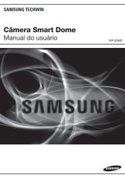
Installation - Video Cable<br />
Installation - UTP cable<br />
Letter Description<br />
A <strong>Dome</strong> ring<br />
B <strong>Dome</strong><br />
C Mounting screws<br />
D <strong>Camera</strong> base<br />
E Power cable<br />
F Video cable / UTP cable<br />
1. Select a mounting surface that is strong enough to support<br />
the camera.<br />
Bosch Security Systems, Inc. Installation Manual TBD | 2.0 | 2010.12
18 en | Installation and Connections <strong>Integrated</strong> <strong>IR</strong> <strong>Dome</strong> <strong>Camera</strong><br />
2. Use the supplied security tool to remove the four (4)<br />
mounting screws (B) of the dome ring (A).<br />
3. Align the supplied mounting template with the selected<br />
mounting surface. Mark the locations of the screw holes<br />
and the cable hole on the mounting surface. (See Figure .)<br />
4. Drill holes for the mounting screws.<br />
5. Drill a hole 1 inch (25 mm) in diameter for routing the<br />
cables.<br />
Note: Alternately, you can route the cables through the 0.5<br />
inch NTP cable entry at the side.<br />
6. Route the power cable (E) and the video cable (F) or UTP<br />
cable (*F) from the camera base through the cable hole in<br />
the surface or out of the NTP cable entry at the side.<br />
7. Align the four (4) screw holes in the camera base with the<br />
screw holes on the mounting surface, and then fasten the<br />
four (4) mounting screws through the camera base into the<br />
mounting surface.<br />
8. Adjust the camera settings as describe in Section 4.<br />
9. Tighten the mounting screws (B) to secure the dome ring<br />
(A) to the camera base (D).<br />
10. Ensure that the rubber ring between the lens and the<br />
dome cover is in place and that it forms a tight seal against<br />
the inside of the dome.<br />
3.2 Connections<br />
CAUTION!<br />
To ensure reliable operation in wet or moist conditions, the<br />
cable leads should be sealed once connected.<br />
TBD | 2.0 | 2010.12 Installation Manual Bosch Security Systems, Inc.
NOTICE<br />
<strong>Integrated</strong> <strong>IR</strong> <strong>Dome</strong> <strong>Camera</strong> Installation and Connections | en 19<br />
Figure 3.1<br />
Connections with video cable<br />
Figure 3.2<br />
Connections with UTP cable<br />
NOTICE!<br />
When using a 12 VDC power supply, check for polarity.<br />
Bosch Security Systems, Inc. Installation Manual TBD | 2.0 | 2010.12
20 en | <strong>Camera</strong> Adjustments <strong>Integrated</strong> <strong>IR</strong> <strong>Dome</strong> <strong>Camera</strong><br />
4 <strong>Camera</strong> Adjustments<br />
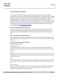
4.1 Adjusting the pan, tilt, and focus/zoom<br />
settings<br />
Figure 4.1<br />
Pan adjustment<br />
Figure 4.2 Tilt adjustment<br />
TBD | 2.0 | 2010.12 Installation Manual Bosch Security Systems, Inc.
<strong>Integrated</strong> <strong>IR</strong> <strong>Dome</strong> <strong>Camera</strong> <strong>Camera</strong> Adjustments | en 21<br />
Figure 4.3<br />
Maximum pan adjustment of 360 degrees<br />
Figure 4.4 Maximum tilt angle of 70 degrees<br />
Bosch Security Systems, Inc. Installation Manual TBD | 2.0 | 2010.12
22 en | <strong>Camera</strong> Adjustments <strong>Integrated</strong> <strong>IR</strong> <strong>Dome</strong> <strong>Camera</strong><br />
Figure 4.5 Maximum tilt angle of 70 degrees<br />
Follow these steps to adjust pan, tilt, and focus/zoom settings:<br />
1. Loosen the 2 cross head screws that secure the pan<br />
position of the camera.<br />
2. Loosen the cross head screw that secures the tilt position<br />
of the camera.<br />
3. Adjust the pan (360˚), tilt (70˚), and rotate as necessary.<br />
4. To adjust the focus and zoom settings, loosen the focus<br />
and zoom adjustment screws located on the camera<br />
module, and adjust until desired image is obtained.<br />
5. Fasten the focus and zoom adjustment screws to fixate<br />
these settings.<br />
6. Fasten the three cross head screws to fixate the camera<br />
position.<br />
NOTICE!<br />
Do not pan or rotate beyond 360˚and do not tilt beyond 70˚ as<br />
shown in Figure 4.3, Figure 4.4, and Figure 4.5 above.<br />
Do not apply excessive force when adjusting the camera<br />
positioning.<br />
TBD | 2.0 | 2010.12 Installation Manual Bosch Security Systems, Inc.
<strong>Integrated</strong> <strong>IR</strong> <strong>Dome</strong> <strong>Camera</strong> On-Screen Menu | en 23<br />
5 On-Screen Menu<br />
5.1 OSD Menu<br />
Exposure Color Day/Night Function Motion Privacy Set<br />
Exit<br />
5.1.1 Exposure Submenu<br />
This menu allows you to set and adjust the lens functions.<br />
LENS<br />
MANUAL/DC<br />
E. SHUTTER AUTO~1/100000<br />
BLC<br />
AGC<br />
OFF~36dB<br />
– MANUAL/DC: A setting for switching between manual and<br />
DC operation of the lens.<br />
– E. SHUTTER: Electronic Shutter - A function that allows you<br />
to set the shutter speed (from 1/60(50) to 1/100K).<br />
– BLC: Backlight Compensation - A function for overcoming<br />
(compensating for) the light behind the object of interest<br />
in a scene. BLC selectively amplifies parts of the image to<br />
compensate for large contrast differences when part of the<br />
image is very brightly lit (for example, a person in a sunlit<br />
doorway).<br />
– AGC: Automatic Gain Control - A function for regulating the<br />
gain or amplification as the light level decreases and the<br />
lens opens fully.<br />
Bosch Security Systems, Inc. Installation Manual TBD | 2.0 | 2010.12
24 en | On-Screen Menu <strong>Integrated</strong> <strong>IR</strong> <strong>Dome</strong> <strong>Camera</strong><br />
5.1.2 Color Submenu<br />
This menu allows you to control and adjust the RGB level for<br />
the camera to represent accurate white color.<br />
WB MODE<br />
AWC<br />
ATW<br />
MANUAL<br />
PUSH LOCK<br />
– WB MODE: White Balance Mode<br />
– AWC: Auto White Balance - A function that allows a color<br />
camera to adjust its output color automatically to give a<br />
natural color independent of the lighting used.<br />
– ATW: Auto Tracking White balance - A function that allows<br />
the camera to adjust white balance constantly for optimal<br />
color reproduction.<br />
– MANUAL: A function that allows manual adjustment of the<br />
white balance.<br />
– PUSH LOCK: A function that enables you to set up<br />
automatically, readjusted only at the request of the user.<br />
5.1.3 Day/Night Submenu<br />
This menu allows you to set the day/night mode in order to<br />
adjust the output image depending on the light levels.<br />
D&N MODE<br />
AUTO<br />
COLOR<br />
B/W<br />
TBD | 2.0 | 2010.12 Installation Manual Bosch Security Systems, Inc.
<strong>Integrated</strong> <strong>IR</strong> <strong>Dome</strong> <strong>Camera</strong> On-Screen Menu | en 25<br />
– AUTO: In this mode, the camera output switches<br />
automatically between color and day/night modes,<br />
depending on light levels.<br />
– COLOR: In this mode, the camera output is only in color.<br />
– B/W: In this mode, the camera output is only in black and<br />
white.<br />
5.1.4 Function Submenu<br />
This menu allows you to set and adjust the various camera<br />
functions.<br />
M<strong>IR</strong>ROR<br />
SHARPNESS<br />
GAMMA<br />
SLC<br />
HME<br />
DRC<br />
SET LEVEL<br />
SET LEVEL<br />
– M<strong>IR</strong>ROR: A function that enables you to set up reversed<br />
LEFT and RIGHT images.<br />
– SHARPNESS: A function that enables you to set up<br />
sharpness control.<br />
– GAMMA: A function that enables you to set up<br />
compensation according to gamma value.<br />
– SLC: Side Light Compensation - Select this mode when the<br />
corner of the screen is darker than the center. As the level<br />
increases, the image becomes brighter.<br />
– HME: Highlight Masking Exposure - This function masks the<br />
bright areas on the screen. As the level of HME is<br />
increased, the masking area increases.<br />
– DRC: Dynamic Range Compensation - This function is to<br />
compensate darker images when different exposures are<br />
in one scene.<br />
Bosch Security Systems, Inc. Installation Manual TBD | 2.0 | 2010.12
26 en | On-Screen Menu <strong>Integrated</strong> <strong>IR</strong> <strong>Dome</strong> <strong>Camera</strong><br />
5.1.5 Motion Submenu<br />
This menu allows you to set the parameters for the camera to<br />
monitor the movement of the image in 64 different areas of the<br />
screen, and trigger an alarm that appears on the screen.<br />
ALARM<br />
SET WINDOW<br />
ALL SET<br />
ALL CLEAR<br />
SENSITI.<br />
SHOW INDI.<br />
DELAY OUT<br />
– SET WINDOW: With the joystick, select or deselect areas<br />
where you want to detect motion. Only areas in blue are<br />
monitored for movement; the others are ignored/masked.<br />
Figure 5.1 Set Motion Detection area<br />
– ALL SET: Set the entire screen for movement detection.<br />
– ALL CLEAR: Clear the entire screen for movement<br />
detection<br />
– SENSITI.: Sensitivity level - As the sensitivity level<br />
increases, smaller movements are detected.<br />
– SHOW INDI.: The motion detected indicator can be<br />
selected as icon, trace or off.<br />
TBD | 2.0 | 2010.12 Installation Manual Bosch Security Systems, Inc.
<strong>Integrated</strong> <strong>IR</strong> <strong>Dome</strong> <strong>Camera</strong> On-Screen Menu | en 27<br />
– DELAY OUT: The alarm signal display on the screen is<br />
delayed from 1 second to 15 seconds.<br />
5.1.6 Privacy Submenu<br />
This menu allows you to set and adjust the privacy functions<br />
that prevent the camera from viewing parts of the scene.<br />
MASK 1<br />
MASK 2<br />
MASK 3<br />
MASK 4<br />
COLOR SET<br />
SET WINDOW<br />
SET WINDOW<br />
SET WINDOW<br />
SET WINDOW<br />
– MASK 1 - MASK 4: These are the four (4) mask areas that<br />
you can set.<br />
– COLOR SET: A function that enables you to select the color<br />
of the masking cells.<br />
Figure 5.2 Privacy Mask<br />
If “SET WINDOW” is selected, the cell appears on the screen.<br />
To adjust the cell, move the joystick UP / DOWN / RIGHT / LEFT.<br />
Once you have selected the desired privacy mask area, press<br />
the joystick in until the mask area is black, and then move the<br />
joystick any direction to return to the previous screen.<br />
Bosch Security Systems, Inc. Installation Manual TBD | 2.0 | 2010.12
28 en | On-Screen Menu <strong>Integrated</strong> <strong>IR</strong> <strong>Dome</strong> <strong>Camera</strong><br />
5.1.7 Setup Submenu<br />
This menu allows you to set miscellaneous parameters for the<br />
OSD such as camera ID, language, etc.<br />
CAMERA ID<br />
TITLE EDIT<br />
TITLE RESET<br />
TITLE POSITION<br />
DPC SET<br />
LANGUAGE<br />
PC CONT.<br />
WHITE THR.<br />
BLACK THR.<br />
DPC LEVEL<br />
ENG/CHA<br />
– CAMERA ID: This is where you set the ID (title) of the<br />
camera.<br />
– TITLE EDIT: This is where you select the value for the<br />
camera title.<br />
– TITLE RESET: This is where you clear the value of the<br />
camera title.<br />
– TITLE POSITION: This is where you select the area to<br />
display the title.<br />
– DPC SET: Defect Pixel Cancellation Set - This function<br />
automatically removes dead pixels in real time.<br />
– LANGUAGE: This is where you set the language (English,<br />
Chinese).<br />
– PC CONT.: This function enables you to set PC<br />
communication (by selecting ON).<br />
5.1.8 Exit Submenu<br />
This menu allows you to exit the OSD menu with or without<br />
saving your settings.<br />
TBD | 2.0 | 2010.12 Installation Manual Bosch Security Systems, Inc.
<strong>Integrated</strong> <strong>IR</strong> <strong>Dome</strong> <strong>Camera</strong> On-Screen Menu | en 29<br />
EXIT<br />
SAVE & EXIT<br />
FACTORY SET<br />
– EXIT: Exit the OSD menu.<br />
– SAVE & EXIT: Save your settings and then exit the OSD<br />
menu.<br />
– FACTORY SET: Restore the factory defaults of the OSD<br />
menu.<br />
NOTICE!<br />
The settings for Lens, Day & Night, and ID/Title stay the same<br />
even after a FACTORY SET.<br />
Bosch Security Systems, Inc. Installation Manual TBD | 2.0 | 2010.12
30 en | Troubleshooting <strong>Integrated</strong> <strong>IR</strong> <strong>Dome</strong> <strong>Camera</strong><br />
6 Troubleshooting<br />
6.1 Troubleshooting<br />
Before sending the camera out for repair, check the items<br />
below. If the problem persists after checking these items,<br />
contact your service center.<br />
- If no image appears, verify that:<br />
– The coaxial cable is attached securely.<br />
– The power and voltage are normal.<br />
– The iris of the lens inside the camera was adjusted<br />
correctly (with the level volume).<br />
– There is adequate illumination.<br />
- If the image is unclear, verify that:<br />
– The lens is in focus.<br />
– The lens is not dirty. Dirt or fingerprints on the lens can<br />
adversely affect the images. Gently wipe any dirt or<br />
fingerprints off the lens with a soft cloth or lens cleaning<br />
paper and cleaning fluid (available commercially).<br />
– The monitor is adjusted correctly.<br />
TBD | 2.0 | 2010.12 Installation Manual Bosch Security Systems, Inc.
<strong>Integrated</strong> <strong>IR</strong> <strong>Dome</strong> <strong>Camera</strong> Technical Specifications | en 31<br />
7 Technical Specifications<br />
Electrical<br />
Power<br />
consumption<br />
Video<br />
12 VDC 10 - 16 V<br />
24 VAC 20 - 28 V<br />
with LED on DC = Max 6.7 W<br />
AC = Max 8 W<br />
Signal Format NTSC PAL<br />
CCD Type<br />
1/3” 410 K Pixels<br />
Color<br />
1/3” 470 K<br />
Pixels Color<br />
Horizontal<br />
520 TVL (Color); 560 TVL (B&W)<br />
Resolution<br />
Total Pixels 811 x 508 795 x 596<br />
Lens<br />
<strong>IR</strong>-corrected, varifocal 5 - 50 mm<br />
Signal-to-Noise > 48 - 50 dB (with AGC off)<br />
Ratio<br />
Sensitivity/<br />
Min. Illumination<br />
0.1 Lux (F1.2, 30 <strong>IR</strong>E) at Color<br />
0.001 Lux (F1.2, 30 <strong>IR</strong>E) at B&W<br />
0 Lux (with infrared on)<br />
Gamma 0.45<br />
Sync System Internal/External<br />
Mechanical<br />
Dimension<br />
Weight<br />
Construction<br />
Finish<br />
<strong>Camera</strong> Pan/Tilt Range<br />
Φ 98mm x 202mm (L)<br />
1.7kg (3.8lbs)<br />
Robust aluminum extrusion<br />
Anodized silver<br />
Pan: 360° total<br />
Tilt: 90° total<br />
Bosch Security Systems, Inc. Installation Manual TBD | 2.0 | 2010.12
32 en | Technical Specifications <strong>Integrated</strong> <strong>IR</strong> <strong>Dome</strong> <strong>Camera</strong><br />
Environmental<br />
Rating<br />
Operating Temperature<br />
Storage Temperature<br />
Operating Humidity<br />
IP66<br />
-10 °C to +55 °C (14 °F to 131 °F)<br />
-20 °C to +70 °C (-4 °F to 158 °F)<br />
under 90% (non-condensing)<br />
TBD | 2.0 | 2010.12 Installation Manual Bosch Security Systems, Inc.
<strong>Integrated</strong> <strong>IR</strong> <strong>Dome</strong> <strong>Camera</strong> Technical Specifications | en 33<br />
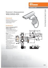
Dimensions<br />
Below are several dimensional drawings of the camera. Unit of<br />
measure is mm.<br />
Figure 7.1 Bottom view<br />
Bosch Security Systems, Inc. Installation Manual TBD | 2.0 | 2010.12
34 en | Technical Specifications <strong>Integrated</strong> <strong>IR</strong> <strong>Dome</strong> <strong>Camera</strong><br />
Figure 7.2 Side view<br />
TBD | 2.0 | 2010.12 Installation Manual Bosch Security Systems, Inc.
Bosch Security Systems, Inc.<br />
850 Greenfield Road<br />
Lancaster, PA 17601<br />
U.S.A.<br />
www.boschsecurity.com<br />
© Bosch Security Systems, Inc., 2011