Laser Tracking on the CD Scaled Views of a Compact Disc
Laser Tracking on the CD Scaled Views of a Compact Disc
Laser Tracking on the CD Scaled Views of a Compact Disc

Create successful ePaper yourself
Turn your PDF publications into a flip-book with our unique Google optimized e-Paper software.
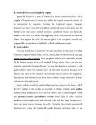
<str<strong>on</strong>g>Laser</str<strong>on</strong>g> <str<strong>on</strong>g>Tracking</str<strong>on</strong>g> <strong>on</strong> <strong>the</strong> <strong>CD</strong><br />
The laser beam in <strong>the</strong> compact disc player must precisely track a row <strong>of</strong> pits which encode <strong>the</strong><br />
binary data <strong>on</strong> <strong>the</strong> disc. In <strong>the</strong> "three-beam" system, a grating is used to produce <strong>the</strong> first order<br />
diffracti<strong>on</strong> maximum to each side <strong>of</strong> <strong>the</strong> main beam. Those diffracted beams overlap <strong>the</strong> track, and<br />
<strong>the</strong> reflected light from <strong>the</strong> two side beams should be equal, <strong>on</strong> <strong>the</strong> average, if <strong>the</strong> main beam is<br />
centered <strong>on</strong> <strong>the</strong> track. If <strong>the</strong>y are unequal, <strong>the</strong>n <strong>the</strong>ir difference can be used to generate an error<br />
voltage to correct <strong>the</strong> tracking. The illustrati<strong>on</strong> <strong>of</strong> <strong>the</strong> side beam positi<strong>on</strong>s is not to scale; <strong>the</strong>y<br />
deviate about 20 micrometers from <strong>the</strong> main beam.<br />
<strong>Scaled</strong> <strong>Views</strong> <strong>of</strong> a <strong>Compact</strong> <strong>Disc</strong><br />
Data <strong>on</strong> a compact disc is stored in <strong>the</strong> form <strong>of</strong> pits in <strong>the</strong> plastic substrate.<br />
A reflective layer <strong>of</strong> aluminium is applied to reflect <strong>the</strong> laser beam. A protective coating is <strong>the</strong>n<br />
applied to <strong>the</strong> top. The laser system reads <strong>the</strong> data from below.
Detecti<strong>on</strong> <strong>of</strong> <strong>CD</strong> Pits<br />
The tracking laser beam sees <strong>the</strong> pits as raised areas which are about a quarter-wavelength high for<br />
<strong>the</strong> laser light.<br />
The reflected light from <strong>the</strong> pit is <strong>the</strong>n 180° out <strong>of</strong> phase with <strong>the</strong> reflecti<strong>on</strong> from <strong>the</strong> flat area, so <strong>the</strong><br />
reflected light intensity drops as <strong>the</strong> beam moves over a pit. The threshold <strong>of</strong> <strong>the</strong> photodiode<br />
detector can be adjusted to switch <strong>on</strong> this light level change.<br />
<strong>CD</strong> Resp<strong>on</strong>se to Defects<br />
The signal from a compact disc is relatively insensitive to <strong>the</strong> presence <strong>of</strong> small defects such as dust<br />
or fine scratches <strong>on</strong> <strong>the</strong> bottom surface <strong>of</strong> <strong>the</strong> <strong>CD</strong> because <strong>the</strong> laser beam is fairly large at that point,<br />
about 0.8 mm. As illustrated below, typical dust particles are much smaller than that. As <strong>the</strong> laser is<br />
fur<strong>the</strong>r focused down to about 1.7 micrometers at <strong>the</strong> depth <strong>of</strong> <strong>the</strong> pits, any shadow from <strong>the</strong> small<br />
defects is blurred and indistinct and does not cause a read error. Larger defects are handled by errorcorrecting<br />
codes in <strong>the</strong> handling <strong>of</strong> <strong>the</strong> digital data.<br />
Error-Correcti<strong>on</strong> <strong>of</strong> <strong>CD</strong> Signals<br />
The data <strong>on</strong> a compact disc is encoded in such a way that some well- developed error-correcti<strong>on</strong><br />
schemes can be used. A sophisticated error- correcti<strong>on</strong> code known as CIRC (cross interleave Reed-<br />
Solom<strong>on</strong> code) is used to deal with both burst errors from dirt and scratches and random errors from<br />
inaccurate cutting <strong>of</strong> <strong>the</strong> disc. The data <strong>on</strong> <strong>the</strong> disc are formatted in frames which c<strong>on</strong>tain 408 bits <strong>of</strong><br />
audio data and ano<strong>the</strong>r 180 bits <strong>of</strong> data which include parity and sync bits and a subcode. A given<br />
frame can c<strong>on</strong>tain informati<strong>on</strong> from o<strong>the</strong>r frames and <strong>the</strong> correlati<strong>on</strong> between frames can be used to<br />
minimize errors. Errors <strong>on</strong> <strong>the</strong> disc could lead to some output frequencies above 22kHz (half <strong>the</strong><br />
sampling frequency <strong>of</strong> 44.1 kHz) which could cause serious problems by "aliasing" down to audible<br />
frequencies. A technique called oversampling is used to reduce such noise. Using a digital filter to<br />
sample four times and average provides a 6-decibel improvement in signal-to-noise ratio. For more<br />
details, see <strong>the</strong> references.
Data Encoding <strong>on</strong> <strong>Compact</strong> <strong>Disc</strong>s<br />
When <strong>the</strong> laser in a compact disc player sweeps over <strong>the</strong> track <strong>of</strong> pits which represents <strong>the</strong> data, a<br />
transiti<strong>on</strong> from a flat area to a pit area or vice versa is interpreted as a binary 1, and <strong>the</strong> absence <strong>of</strong> a<br />
transiti<strong>on</strong> in a time interval called a clock cycle is interpreted as a binary 0. This kind <strong>of</strong> detecti<strong>on</strong> is<br />
called an NRZI code. The particular NRZI code used with compact discs is EFM (eight-to-fourteen<br />
modulati<strong>on</strong>) in which eight bits <strong>of</strong> data are represented by fourteen channel bits. In additi<strong>on</strong> to <strong>the</strong><br />
actual digital sound data, parity and sync bits and a subcode are also recorded <strong>on</strong> <strong>the</strong> disc in<br />
"frames" . In a given frame, 408 bits <strong>of</strong> audio data are recorded with ano<strong>the</strong>r 180 bits <strong>of</strong> data which<br />
permit a sophisticated error-correcti<strong>on</strong> code to be used. A given frame can c<strong>on</strong>tain informati<strong>on</strong> from<br />
o<strong>the</strong>r frames and <strong>the</strong> correlati<strong>on</strong> between frames can be used to minimize errors. In additi<strong>on</strong> to<br />
detecti<strong>on</strong>, a significant amount <strong>of</strong> computati<strong>on</strong> must be d<strong>on</strong>e to decode <strong>the</strong> signal and prepare it for<br />
c<strong>on</strong>versi<strong>on</strong> back to analog form with a DAC.<br />
Detecti<strong>on</strong> <strong>of</strong> <strong>Compact</strong> <strong>Disc</strong> Data<br />
The pits which encode <strong>the</strong> digital data <strong>on</strong> a compact disc are tracked by a laser. The reflected light<br />
from <strong>the</strong> pits is out <strong>of</strong> phase with that from <strong>the</strong> surrounding area, so <strong>the</strong> reflected light intensity<br />
drops when <strong>the</strong> laser moves over a pit area. The nature <strong>of</strong> a photodiode is such that it can be used as<br />
<strong>the</strong> sensing element in a light-activated switch. It c<strong>on</strong>ducts an electric current which is proporti<strong>on</strong>al<br />
to <strong>the</strong> light falling <strong>on</strong> it. The photodiode and switch can be adjusted so that a transiti<strong>on</strong> to a pit area<br />
will switch it <strong>of</strong>f, and a transiti<strong>on</strong> from a pit area will switch it <strong>on</strong>. Ei<strong>the</strong>r transiti<strong>on</strong> is interpreted as<br />
a binary 1, while <strong>the</strong> absence <strong>of</strong> a transiti<strong>on</strong> in a given clock cycle is interpreted as a binary zero.<br />
The data <strong>on</strong> <strong>the</strong> disc is encoded in a sophisticated way, so that decoding is necessary before sending<br />
<strong>the</strong> digital signal representing <strong>the</strong> sound to a digital-to-analog c<strong>on</strong>verter (DAC) for rec<strong>on</strong>versi<strong>on</strong> to<br />
analog form.<br />
Cylindrical Lens for Positi<strong>on</strong>ing<br />
A clever use <strong>of</strong> a cylindrical lens generates a correcti<strong>on</strong> signal to positi<strong>on</strong> <strong>the</strong> main focusing lens for<br />
<strong>the</strong> detector in a compact disc player. The combinati<strong>on</strong> <strong>of</strong> a symmetric lens and a cylindrical lens<br />
produces a circular beam at <strong>on</strong>ly <strong>on</strong>e distance past <strong>the</strong> cylindrical lens. A segmented photodiode<br />
arrangement can detect whe<strong>the</strong>r <strong>the</strong> beam is circular and generate an error voltage to repositi<strong>on</strong> <strong>the</strong><br />
main lens so that it is. The error voltage drives a coil which can rapidly repositi<strong>on</strong> <strong>the</strong> lens in<br />
resp<strong>on</strong>se to changes in distance to <strong>the</strong> <strong>CD</strong> as it rotates.
<strong>CD</strong> Storage Capacity<br />
A compact disc can store more than 6 billi<strong>on</strong> bits <strong>of</strong> binary data. This is equivalent to 782<br />
megabytes, and at 2000 characters per page this is equivalent to about 275,000 pages <strong>of</strong> text<br />
(Rossing). Because <strong>the</strong> analog-to-digital c<strong>on</strong>versi<strong>on</strong> for making <strong>CD</strong>'s samples sound waveforms at<br />
44.1 kHz, <strong>the</strong> amount <strong>of</strong> data involved in <strong>the</strong> recording <strong>of</strong> high-fidelity sound is very large. The 12<br />
cm diameter compact disc can hold 74 minutes <strong>of</strong> digital audio which has a frequencies over <strong>the</strong> full<br />
audible range <strong>of</strong> 20-20,000 Hz. The signal-to-noise ratio and <strong>the</strong> dynamic range can exceed 90<br />
decibels.<br />
Calcite<br />
Two images through<br />
calcite crystal<br />
Polarizer transmits <strong>the</strong><br />
ordinary ray.<br />
Polarizer rotated about 90°<br />
transmits <strong>the</strong> extraordinary ray.<br />
Because <strong>of</strong> its birefringence, calcite forms two images <strong>of</strong> <strong>the</strong> arrow. Rotating a polarizer over <strong>the</strong>m<br />
shows that <strong>the</strong> light which forms <strong>the</strong> two images is polarized at right angles.<br />
Calcite<br />
These three clear calcite crystals are just <strong>the</strong> beginning <strong>of</strong> <strong>the</strong> vast variety <strong>of</strong> forms in which calcite<br />
appears. Since it is soluble in acidic water, it can be dissolved and recrystallized with a large<br />
number <strong>of</strong> different inclusi<strong>on</strong>s. All <strong>of</strong> <strong>the</strong> samples pictured here are <strong>on</strong> display at <strong>the</strong> Smiths<strong>on</strong>ian<br />
Museum <strong>of</strong> Natural History. The indices <strong>of</strong> refracti<strong>on</strong> for <strong>the</strong> o- and e-rays are 1.6584 and 1.4864
espectively. This gives total internal reflecti<strong>on</strong> critical angles <strong>of</strong> 37.08° for <strong>the</strong> o- and 42.28° for <strong>the</strong><br />
e-rays when in c<strong>on</strong>tact with air. This means that for any angle between <strong>the</strong>se two values, <strong>the</strong> o-ray<br />
will be totally reflected but <strong>the</strong> e-ray will be partially transmitted. This gives linear polarizati<strong>on</strong><br />
since <strong>on</strong>ly <strong>the</strong> e-ray emerges.<br />
Calcite is used in polarizing prisms such as <strong>the</strong> Nicol prism, <strong>the</strong> Glan-Foucault prism, and <strong>the</strong><br />
Wollast<strong>on</strong> prism.<br />
Calcite, CaCO 3 , is <strong>the</strong> most abundant <strong>of</strong> <strong>the</strong> carb<strong>on</strong>ate minerals.<br />
Clear calcite has many optical applicati<strong>on</strong>s because <strong>of</strong> its large birefringence.<br />
Calcite manganoan. From Idarado Mine, Ouray, Colorado. Sample size 15-18 cm.<br />
Calcite with duftite inclusi<strong>on</strong>s from Tsumeb, Namibia. Sample size about 12 cm.<br />
From Tsumeb, Namibia. Sample size about 12cm
Both calcite samples above are about 12-15 cm in width. The right image above is from Santa<br />
Eulala, Mexico<br />
Calcite<br />
The varieties <strong>of</strong> calcite, CaCO 3 , are so numerous and so varied that an entire display case at <strong>the</strong><br />
Smiths<strong>on</strong>ian Museum <strong>of</strong> Natural History is devoted to just calcite. Calcite is <strong>the</strong> most abundant <strong>of</strong><br />
<strong>the</strong> carb<strong>on</strong>ate minerals. The sample shown above and in <strong>the</strong> closeup view below is called cobaltian<br />
calcite. The sample is about 9x12 cm. The 3.9 carat gem at right is from Spain. All <strong>the</strong>se samples<br />
are part <strong>of</strong> <strong>the</strong> gem and mineral exhibit at <strong>the</strong> Smiths<strong>on</strong>ian Museum <strong>of</strong> Natural History.
The calcite gem above is 52.3 carats and is from Balmat, New York. At right above is a 110.7 carat<br />
calcite gem from Africa. The 122.3 carat gem below right is from Chihuahua, Mexico. The large<br />
gem below is 1865 carats and is from Balmat, New York.
The red calcite gem above is 150.6 carats and <strong>the</strong> gem at right is 70.2 carats. They are from Baja<br />
California, Mexico<br />
The faceted calcite ball above left is about 3.5x3.5 cm. The oval-cut gem above right is about 8x6<br />
cm.
This huge single crystal <strong>of</strong> calcite is about 30x45 cm and is from Iceberg claim, Dix<strong>on</strong>, New<br />
Mexico. It shows <strong>the</strong> characteristic calcite geometry and shows <strong>the</strong> large birefringence <strong>of</strong> calcite in<br />
<strong>the</strong> double image <strong>of</strong> <strong>the</strong> text placed behind it.<br />
Calcite<br />
The mineral calcite, also known as Iceland spar, is a widely used material in optics because <strong>of</strong> its<br />
birefringence. Its birefringence is so large that a calcite crystal placed over a dot <strong>on</strong> a page will<br />
reveal two distinct images <strong>of</strong> <strong>the</strong> dot. One image will remain fixed as <strong>the</strong> crystal is rotated, and that<br />
ray through <strong>the</strong> crystal is called <strong>the</strong> "ordinary ray" since it behaves just as a ray through glass.<br />
However, <strong>the</strong> o<strong>the</strong>r image will rotate with <strong>the</strong> crystal, tracing out a small circle around <strong>the</strong> ordinary<br />
image. This ray is called <strong>the</strong> "extraordinary ray".<br />
The indices <strong>of</strong> refracti<strong>on</strong> for <strong>the</strong> o- and e-rays are 1.6584 and 1.4864 respectively. This gives total<br />
internal reflecti<strong>on</strong> critical angles <strong>of</strong> 37.08° for <strong>the</strong> o- and 42.28° for <strong>the</strong> e-rays when in c<strong>on</strong>tact with<br />
air. This means that for any angle between <strong>the</strong>se two values, <strong>the</strong> o-ray will be totally reflected but<br />
<strong>the</strong> e-ray will be partially transmitted. This gives linear polarizati<strong>on</strong> since <strong>on</strong>ly <strong>the</strong> e-ray emerges.<br />
Calcite is used in polarizing prisms such as <strong>the</strong> Nicol prism, <strong>the</strong> Glan-Foucault prism, and <strong>the</strong><br />
Wollast<strong>on</strong> prism.<br />
A simple dem<strong>on</strong>strati<strong>on</strong> <strong>of</strong> <strong>the</strong> large birefringence <strong>of</strong> calcite is to put a dot <strong>on</strong> a piece <strong>of</strong> paper and<br />
put <strong>the</strong> calcite crystal over it. You see two distinct dots. By putting a piece <strong>of</strong> polaroid over <strong>the</strong><br />
crystal and rotating it, you can show that <strong>the</strong> two images <strong>of</strong> <strong>the</strong> dot are made up <strong>of</strong> light polarized at<br />
90° with respect to each o<strong>the</strong>r. Rotating <strong>the</strong> polaroid will show <strong>on</strong>e dot, <strong>the</strong>n both in transiti<strong>on</strong>, and<br />
<strong>the</strong>n just <strong>the</strong> sec<strong>on</strong>d dot as you reach 90°.<br />
The video segment below shows <strong>the</strong> successive disappearance <strong>of</strong> <strong>the</strong> two dots as a sheet <strong>of</strong> polaroid<br />
is rotated over <strong>the</strong>m
Fresnel's Equati<strong>on</strong>s<br />
Fresnel's equati<strong>on</strong>s describe <strong>the</strong> reflecti<strong>on</strong> and transmissi<strong>on</strong> <strong>of</strong> electromagnetic waves at an<br />
interface. That is, <strong>the</strong>y give <strong>the</strong> reflecti<strong>on</strong> and transmissi<strong>on</strong> coefficients for waves parallel and<br />
perpendicular to <strong>the</strong> plane <strong>of</strong> incidence. For a dielectric medium where Snell's Law can be used to<br />
relate <strong>the</strong> incident and transmitted angles, Fresnel's Equati<strong>on</strong>s can be stated in terms <strong>of</strong> <strong>the</strong> angles <strong>of</strong><br />
incidence and transmissi<strong>on</strong>.<br />
For light from a medium <strong>of</strong> index n 1 =<br />
incident up<strong>on</strong> a medium <strong>of</strong> index n 2 =<br />
at an angle θ i = °<br />
<strong>the</strong> angle <strong>of</strong> transmissi<strong>on</strong> is θ t = °<br />
Fresnel's equati<strong>on</strong>s give <strong>the</strong> reflecti<strong>on</strong> coefficients:<br />
= and =<br />
The transmissi<strong>on</strong> coefficients are<br />
= and<br />
=<br />
Note that <strong>the</strong>se coefficients are fracti<strong>on</strong>al amplitudes, and must be squared to get fracti<strong>on</strong>al<br />
intensities for reflecti<strong>on</strong> and transmissi<strong>on</strong>. The signs <strong>of</strong> <strong>the</strong> coefficients depend <strong>on</strong> <strong>the</strong> original<br />
choices <strong>of</strong> field directi<strong>on</strong>s.<br />
You can choose values <strong>of</strong> parameters which will give transmissi<strong>on</strong> coefficients greater than 1, and<br />
that would appear to violate c<strong>on</strong>servati<strong>on</strong> <strong>of</strong> energy. (For example, try light incident from a medium
<strong>of</strong> n 1 =1.5 up<strong>on</strong> a medium <strong>of</strong> n 2 =1.0 with an angle <strong>of</strong> incidence <strong>of</strong> 30°.) But <strong>the</strong> square <strong>of</strong> <strong>the</strong><br />
transmissi<strong>on</strong> coefficient gives <strong>the</strong> transmitted energy flux per unit area (intensity), and <strong>the</strong> area <strong>of</strong><br />
<strong>the</strong> transmitted beam is smaller in <strong>the</strong> refracted beam than in <strong>the</strong> incident beam if <strong>the</strong> index <strong>of</strong><br />
refracti<strong>on</strong> is less than that <strong>of</strong> <strong>the</strong> incident medium. When you take <strong>the</strong> intensity times <strong>the</strong> area for<br />
both <strong>the</strong> reflected and refracted beams, <strong>the</strong> total energy flux must equal that in <strong>the</strong> incident beam.<br />
For fur<strong>the</strong>r details, see Jenkins and White.<br />
Checking out c<strong>on</strong>servati<strong>on</strong> <strong>of</strong> energy in this situati<strong>on</strong> leads to <strong>the</strong> relati<strong>on</strong>ship<br />
which applies to both <strong>the</strong> parallel and perpendicular cases.<br />
Parallel case: Reflected % and transmitted %.<br />
Perpendicular case: Reflected % and transmitted %.<br />
Reflecti<strong>on</strong> and Transmissi<strong>on</strong><br />
Typical reflecti<strong>on</strong> and transmissi<strong>on</strong> curves for external reflecti<strong>on</strong>. These curves are <strong>the</strong> graphical<br />
representati<strong>on</strong> <strong>of</strong> <strong>the</strong> Fresnel equati<strong>on</strong>s. Note that <strong>the</strong> reflected amplitude for <strong>the</strong> light polarized<br />
parallel to <strong>the</strong> incident plane is zero for a specific angle called <strong>the</strong> Brewster angle. The reflected<br />
light is <strong>the</strong>n linearly polarized in a plane perpendicular to <strong>the</strong> incident plane. This polarizati<strong>on</strong> by<br />
reflecti<strong>on</strong> is exploited in numerous optical devices<br />
Internal Reflecti<strong>on</strong> Curves<br />
The illustrati<strong>on</strong> shows typical reflecti<strong>on</strong> curves for internal reflecti<strong>on</strong>. Internal reflecti<strong>on</strong> implies<br />
that <strong>the</strong> reflecti<strong>on</strong> is from an interface to a medium <strong>of</strong> lesser index <strong>of</strong> refracti<strong>on</strong>, as from water to<br />
air. These curves are <strong>the</strong> graphical representati<strong>on</strong> <strong>of</strong> <strong>the</strong> Fresnel equati<strong>on</strong>s. Note that <strong>the</strong> reflected
amplitude for <strong>the</strong> light polarized parallel to <strong>the</strong> incident plane is zero for a specific angle called <strong>the</strong><br />
Brewster angle. The reflected light is <strong>the</strong>n linearly polarized in a plane perpendicular to <strong>the</strong> incident<br />
plane. This polarizati<strong>on</strong> by reflecti<strong>on</strong> is exploited in numerous optical devices. Ano<strong>the</strong>r<br />
characteristic <strong>of</strong> internal reflecti<strong>on</strong> is that <strong>the</strong>re is always an angle <strong>of</strong> incidence c above which all<br />
light is reflected back into <strong>the</strong> medium. This phenomen<strong>on</strong> <strong>of</strong> total internal reflecti<strong>on</strong> has many<br />
practical applicati<strong>on</strong>s in optics.<br />
Reflecti<strong>on</strong> and Transmissi<strong>on</strong><br />
External Reflecti<strong>on</strong><br />
Fresnel's equati<strong>on</strong>s describe <strong>the</strong> reflecti<strong>on</strong> and transmissi<strong>on</strong> <strong>of</strong> electromagnetic waves at an<br />
interface. That is, <strong>the</strong>y give <strong>the</strong> reflecti<strong>on</strong> and transmissi<strong>on</strong> coefficients for waves parallel and<br />
perpendicular to <strong>the</strong> plane <strong>of</strong> incidence. For a dielectric medium where Snell's Law can be used to<br />
relate <strong>the</strong> incident and transmitted angles, Fresnel's Equati<strong>on</strong>s can be stated in terms <strong>of</strong> <strong>the</strong> angles <strong>of</strong><br />
incidence and transmissi<strong>on</strong>.
For light from a medium <strong>of</strong> index =<br />
incident up<strong>on</strong> a medium <strong>of</strong> index =<br />
at an angle = °<br />
<strong>the</strong> angle <strong>of</strong> transmissi<strong>on</strong> is = °<br />
Fresnel's equati<strong>on</strong>s give <strong>the</strong> reflecti<strong>on</strong> coefficients:<br />
= and =<br />
The transmissi<strong>on</strong> coefficients are<br />
= and<br />
=<br />
Note that <strong>the</strong>se coefficients are fracti<strong>on</strong>al amplitudes, and must be squared to get fracti<strong>on</strong>al<br />
intensities for reflecti<strong>on</strong> and transmissi<strong>on</strong>.<br />
You can choose values <strong>of</strong> parameters which will give transmissi<strong>on</strong> coefficients greater than 1, and<br />
that would appear to violate c<strong>on</strong>servati<strong>on</strong> <strong>of</strong> energy. (For example, try light incident from a medium<br />
<strong>of</strong> n 1 =1.5 up<strong>on</strong> a medium <strong>of</strong> n 2 =1.0 with an angle <strong>of</strong> incidence <strong>of</strong> 30°.) But <strong>the</strong> square <strong>of</strong> <strong>the</strong><br />
transmissi<strong>on</strong> coefficient gives <strong>the</strong> transmitted energy flux per unit area (intensity), and <strong>the</strong> area <strong>of</strong><br />
<strong>the</strong> transmitted beam is smaller in <strong>the</strong> refracted beam than in <strong>the</strong> incident beam if <strong>the</strong> index <strong>of</strong><br />
refracti<strong>on</strong> is less than that <strong>of</strong> <strong>the</strong> incident medium. When you take <strong>the</strong> intensity times <strong>the</strong> area for<br />
both <strong>the</strong> reflected and refracted beams, <strong>the</strong> total energy flux must equal that in <strong>the</strong> incident beam.<br />
For fur<strong>the</strong>r details, see Jenkins and White.<br />
Checking out c<strong>on</strong>servati<strong>on</strong> <strong>of</strong> energy in this situati<strong>on</strong> leads to <strong>the</strong> relati<strong>on</strong>ship
which applies to both <strong>the</strong> parallel and perpendicular cases.<br />
Parallel case: Reflected % and transmitted %.<br />
Perpendicular case: Reflected % and transmitted %.<br />
Reflecti<strong>on</strong> and Transmissi<strong>on</strong><br />
Internal Reflecti<strong>on</strong><br />
Fresnel's equati<strong>on</strong>s describe <strong>the</strong> reflecti<strong>on</strong> and transmissi<strong>on</strong> <strong>of</strong> electromagnetic waves at an<br />
interface. That is, <strong>the</strong>y give <strong>the</strong> reflecti<strong>on</strong> and transmissi<strong>on</strong> coefficients for waves parallel and<br />
perpendicular to <strong>the</strong> plane <strong>of</strong> incidence. For a dielectric medium where Snell's Law can be used to<br />
relate <strong>the</strong> incident and transmitted angles, Fresnel's Equati<strong>on</strong>s can be stated in terms <strong>of</strong> <strong>the</strong> angles <strong>of</strong><br />
incidence and transmissi<strong>on</strong>.<br />
For light from a medium <strong>of</strong> index =<br />
incident up<strong>on</strong> a medium <strong>of</strong> index =<br />
at an angle = °<br />
<strong>the</strong> angle <strong>of</strong> transmissi<strong>on</strong> is = °<br />
Fresnel's equati<strong>on</strong>s give <strong>the</strong> reflecti<strong>on</strong> coefficients:
= and =<br />
The transmissi<strong>on</strong> coefficients are<br />
= and<br />
=<br />
Note that <strong>the</strong>se coefficients are fracti<strong>on</strong>al amplitudes, and must be squared to get fracti<strong>on</strong>al<br />
intensities for reflecti<strong>on</strong> and transmissi<strong>on</strong>.<br />
You can choose values <strong>of</strong> parameters which will give transmissi<strong>on</strong> coefficients greater than 1, and<br />
that would appear to violate c<strong>on</strong>servati<strong>on</strong> <strong>of</strong> energy. (For example, try light incident from a medium<br />
<strong>of</strong> n 1 =1.5 up<strong>on</strong> a medium <strong>of</strong> n 2 =1.0 with an angle <strong>of</strong> incidence <strong>of</strong> 30°.) But <strong>the</strong> square <strong>of</strong> <strong>the</strong><br />
transmissi<strong>on</strong> coefficient gives <strong>the</strong> transmitted energy flux per unit area (intensity), and <strong>the</strong> area <strong>of</strong><br />
<strong>the</strong> transmitted beam is smaller in <strong>the</strong> refracted beam than in <strong>the</strong> incident beam if <strong>the</strong> index <strong>of</strong><br />
refracti<strong>on</strong> is less than that <strong>of</strong> <strong>the</strong> incident medium. When you take <strong>the</strong> intensity times <strong>the</strong> area for<br />
both <strong>the</strong> reflected and refracted beams, <strong>the</strong> total energy flux must equal that in <strong>the</strong> incident beam.<br />
For fur<strong>the</strong>r details, see Jenkins and White.<br />
Checking out c<strong>on</strong>servati<strong>on</strong> <strong>of</strong> energy in this situati<strong>on</strong> leads to <strong>the</strong> relati<strong>on</strong>ship<br />
which applies to both <strong>the</strong> parallel and perpendicular cases.<br />
Parallel case: Reflected % and transmitted %.<br />
Perpendicular case: Reflected % and transmitted %.<br />
Blue Sky<br />
The blue color <strong>of</strong> <strong>the</strong> sky is caused by <strong>the</strong> scattering <strong>of</strong> sunlight <strong>of</strong>f <strong>the</strong> molecules <strong>of</strong> <strong>the</strong><br />
atmosphere. This scattering, called Rayleigh scattering, is more effective at short wavelengths (<strong>the</strong><br />
blue end <strong>of</strong> <strong>the</strong> visible spectrum). Therefore <strong>the</strong> light scattered down to <strong>the</strong> earth at a large angle<br />
with respect to <strong>the</strong> directi<strong>on</strong> <strong>of</strong> <strong>the</strong> sun's light is predominantly in <strong>the</strong> blue end <strong>of</strong> <strong>the</strong> spectrum.
Note that <strong>the</strong> blue <strong>of</strong> <strong>the</strong> sky is more saturated when you look fur<strong>the</strong>r from<br />
<strong>the</strong> sun. The almost white scattering near <strong>the</strong> sun can be attributed to Mie<br />
scattering, which is not very wavelength dependent.<br />
Clouds in c<strong>on</strong>trast to<br />
<strong>the</strong> blue sky appear<br />
white to achromatic<br />
gray.<br />
The water droplets that make up <strong>the</strong> cloud are much larger than <strong>the</strong> molecules <strong>of</strong> <strong>the</strong> air and <strong>the</strong><br />
scattering from <strong>the</strong>m is almost independent <strong>of</strong> wavelength in <strong>the</strong> visible range.<br />
Rayleigh Scattering<br />
Rayleigh scattering refers to <strong>the</strong> scattering <strong>of</strong> light <strong>of</strong>f <strong>of</strong> <strong>the</strong> molecules <strong>of</strong> <strong>the</strong> air, and can be<br />
extended to scattering from particles up to about a tenth <strong>of</strong> <strong>the</strong> wavelength <strong>of</strong> <strong>the</strong> light. It is<br />
Rayleigh scattering <strong>of</strong>f <strong>the</strong> molecules <strong>of</strong> <strong>the</strong> air which gives us <strong>the</strong> blue sky. Lord Rayleigh<br />
calculated <strong>the</strong> scattered intensity from dipole scatterers much smaller than <strong>the</strong> wavelength to be:
Rayleigh scattering can be c<strong>on</strong>sidered to be elastic scattering since <strong>the</strong> phot<strong>on</strong> energies <strong>of</strong> <strong>the</strong><br />
scattered phot<strong>on</strong>s is not changed. Scattering in which <strong>the</strong> scattered phot<strong>on</strong>s have ei<strong>the</strong>r a higher or<br />
lower phot<strong>on</strong> energy is called Raman scattering. Usually this kind <strong>of</strong> scattering involves exciting<br />
some vibrati<strong>on</strong>al mode <strong>of</strong> <strong>the</strong> molecules, giving a lower scattered phot<strong>on</strong> energy, or scattering <strong>of</strong>f<br />
an excited vibrati<strong>on</strong>al state <strong>of</strong> a molecule which adds its vibrati<strong>on</strong>al energy to <strong>the</strong> incident phot<strong>on</strong>.<br />
Mie Scattering<br />
The scattering from molecules and very tiny particles (< 1 /10 wavelength) is predominantly<br />
Rayleigh scattering. For particle sizes larger than a wavelength, Mie scattering predominates. This<br />
scattering produces a pattern like an antenna lobe, with a sharper and more intense forward lobe for<br />
larger particles.<br />
Mie scattering is not str<strong>on</strong>gly wavelength dependent and produces <strong>the</strong> almost white glare around <strong>the</strong><br />
sun when a lot <strong>of</strong> particulate material is present in <strong>the</strong> air. It also gives us <strong>the</strong> <strong>the</strong> white light from<br />
mist and fog.<br />
Greenler in his "Rainbows, Haloes and Glories" has some excellent color plates dem<strong>on</strong>strating Mie<br />
scattering and its dramatic absence in <strong>the</strong> particle-free air <strong>of</strong> <strong>the</strong> polar regi<strong>on</strong>s.<br />
Rayleigh and Mie Scattering
Sky Saturati<strong>on</strong> and Brightness<br />
As a qualitative examinati<strong>on</strong> <strong>of</strong> sky brightness and <strong>the</strong> saturati<strong>on</strong> <strong>of</strong> <strong>the</strong> blue sky color,<br />
measurements <strong>of</strong> <strong>the</strong> color <strong>of</strong> <strong>the</strong> sky photograph were made from a computer m<strong>on</strong>itor using Adobe<br />
Illustrator's color tools. N<strong>on</strong>e <strong>of</strong> <strong>the</strong> data should be taken as quantitatively reliable since <strong>the</strong> original<br />
photo had been transformed several times, and <strong>the</strong> measurements were taken from a n<strong>on</strong>-calibrated<br />
computer m<strong>on</strong>itor. Never<strong>the</strong>less, it might be useful as an example <strong>of</strong> <strong>the</strong> progressi<strong>on</strong>s <strong>of</strong> sky color.<br />
A series <strong>of</strong> points <strong>on</strong> <strong>the</strong> sky image were chosen starting from <strong>the</strong> left, indicated by <strong>the</strong> white dots<br />
superimposed <strong>on</strong> <strong>the</strong> image above. It is clear to <strong>the</strong> eye that <strong>the</strong> progressi<strong>on</strong> leads to a brighter sky<br />
and to a blue color which is less saturated, or more pastel. Measurements <strong>of</strong> <strong>the</strong> color and brightness<br />
were made at each point based <strong>on</strong> amounts <strong>of</strong> red, green and blue present. In <strong>the</strong> graph at upper left,<br />
<strong>the</strong> blue brightness was normalized to 1 and <strong>the</strong> red and green expressed as a fracti<strong>on</strong> <strong>of</strong> <strong>the</strong> blue.<br />
One result was that <strong>the</strong> green was significantly brighter than <strong>the</strong> red. This is c<strong>on</strong>sistent with<br />
Rayleigh scattering which emphasizes <strong>the</strong> shorter wavelengths. Ano<strong>the</strong>r result was that <strong>the</strong> red and<br />
green increased as a fracti<strong>on</strong> <strong>of</strong> <strong>the</strong> blue, indicating that <strong>the</strong> color was becoming less saturated. This<br />
can be interpreted as blue mixed with an increasing fracti<strong>on</strong> <strong>of</strong> white light, which is c<strong>on</strong>sistent with<br />
<strong>the</strong> light being a combinati<strong>on</strong> <strong>of</strong> Rayleigh and Mie scattering. As you approach <strong>the</strong> sun's directi<strong>on</strong>,<br />
<strong>the</strong> Mie scattering accounts for a larger fracti<strong>on</strong> <strong>of</strong> <strong>the</strong> total light, and <strong>the</strong> Mie scattered light is<br />
essentially white. The graph <strong>of</strong> overall brightness above is just <strong>the</strong> sum <strong>of</strong> all three colors, with a<br />
maximum <strong>of</strong> 1 being white <strong>on</strong> <strong>the</strong> m<strong>on</strong>itor. The increasing brightness al<strong>on</strong>g <strong>the</strong> path <strong>of</strong> <strong>the</strong> data is<br />
again c<strong>on</strong>sistent with a combinati<strong>on</strong> <strong>of</strong> Rayleigh and Mie scattering. The Mie scattering has a str<strong>on</strong>g<br />
forward lobe and increases as you approach <strong>the</strong> sun's directi<strong>on</strong>.<br />
Hue<br />
Hue, al<strong>on</strong>g with saturati<strong>on</strong> and brightness make up <strong>the</strong> three distinct attributes <strong>of</strong> color. The terms<br />
"red" and "blue" are primarily describing hue - hue is related to wavelength for spectral colors. It is<br />
c<strong>on</strong>venient to arrange <strong>the</strong> saturated hues around a Newt<strong>on</strong> Color Circle. Starting from red and<br />
proceeding clockwise around <strong>the</strong> circle below to blue proceeds from l<strong>on</strong>g to shorter wavelengths.<br />
However it shows that not all hues can be represented by spectral colors since <strong>the</strong>re is no single<br />
wavelength <strong>of</strong> light which has <strong>the</strong> magenta hue - it may be produced by an equal mixture <strong>of</strong> red and<br />
blue.
There are many different mixtures <strong>of</strong> wavelengths which can produce <strong>the</strong><br />
same perceived hue. The achromatic line from black to gray to white<br />
through <strong>the</strong> center <strong>of</strong> <strong>the</strong> circle represents light which has no hue.<br />
The distributi<strong>on</strong> <strong>of</strong> hue around a circle is used in commercially available paint and pigment mixing<br />
guides like <strong>the</strong> Color Wheel<br />
Saturati<strong>on</strong><br />
Saturati<strong>on</strong>, al<strong>on</strong>g with hue and brightness make up <strong>the</strong> three distinct attributes <strong>of</strong> color. Pink may be<br />
thought <strong>of</strong> as having <strong>the</strong> same hue as red but being less saturated. A fully saturated color is <strong>on</strong>e with<br />
no mixture <strong>of</strong> white. A spectral color c<strong>on</strong>sisting <strong>of</strong> <strong>on</strong>ly <strong>on</strong>e wavelength is fully saturated, but <strong>on</strong>e<br />
can have a fully saturated magenta which is not a spectral color. Quantifying <strong>the</strong> percepti<strong>on</strong> <strong>of</strong><br />
saturati<strong>on</strong> must take into account <strong>the</strong> fact that some spectral colors are perceived to be more<br />
saturated than o<strong>the</strong>rs. For example, m<strong>on</strong>ochromatic reds and violets are perceived to be more<br />
saturated than m<strong>on</strong>ochromatic yellows. There are also more perceptably different levels <strong>of</strong><br />
saturati<strong>on</strong> for some hues - a fact accounted for in <strong>the</strong> Munsell color system<br />
There are many different mixtures <strong>of</strong> wavelengths which can<br />
produce <strong>the</strong> same perceived hue. The achromatic line from<br />
black to gray to white through <strong>the</strong> center <strong>of</strong> <strong>the</strong> circle<br />
represents light which has no hue.
Note that <strong>the</strong> blue <strong>of</strong> <strong>the</strong> sky is more saturated when you look fur<strong>the</strong>r from <strong>the</strong> sun. The almost<br />
white scattering near <strong>the</strong> sun can be attributed to Mie scattering, which is not very wavelength<br />
dependent. The mixture <strong>of</strong> white light with <strong>the</strong> blue gives a less saturated blue.<br />
One <strong>of</strong> <strong>the</strong> features <strong>of</strong> <strong>the</strong> commercially available Color Wheel is to help visualize <strong>the</strong> effect <strong>of</strong><br />
adding white paint or pigment. It makes <strong>the</strong> color less saturated as shown in <strong>the</strong> image below.<br />
Brightness<br />
Brightness, al<strong>on</strong>g with saturati<strong>on</strong> and hue make up <strong>the</strong> three distinct attributes <strong>of</strong> color. The<br />
brightness <strong>of</strong> a colored surface depends up<strong>on</strong> <strong>the</strong> illuminance and up<strong>on</strong> its reflectivity. Since <strong>the</strong><br />
perceived brightness is not linearly proporti<strong>on</strong>al to <strong>the</strong> reflectivity, a scale from 0 to 10 is used to<br />
represent perceived brightness in color measurement systems like <strong>the</strong> Munsell system. It is found<br />
that equal surfaces with differing spectral characteristics but which emit <strong>the</strong> same number <strong>of</strong> lumens<br />
will be perceived to be equally bright.<br />
If <strong>on</strong>e surface emits more lumens, it will be perceived to be brighter in a logarithmic relati<strong>on</strong>ship<br />
which yields a c<strong>on</strong>stant increase in brightness <strong>of</strong> about 1.5 units with each doubling <strong>of</strong> brightness.
The images above from <strong>the</strong> commercially available Color Wheel depict 10 levels <strong>of</strong> brightness for<br />
gray or achromatic light.